
Related Manuals for Navistar MaxxForce 15


Summary of Contents for Navistar MaxxForce 15
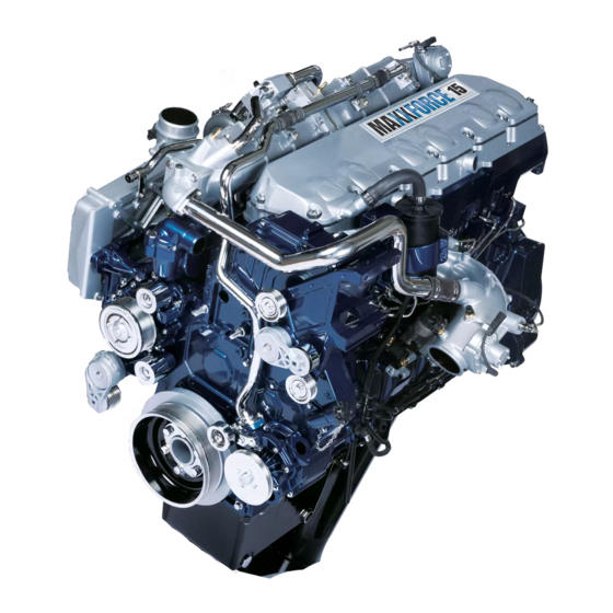
- Page 1 ENGINE SERVICE MANUAL MaxxForce® 15L Diesel Engine Navistar, Inc. 2701 Navistar Drive, Lisle, IL 60532 USA © 2013 Navistar, Inc. All rights reserved. All marks are trademarks of their respective owners.
- Page 3 ENGINE SERVICE MANUAL TABLE OF CONTENTS Foreword........................1 Service Diagnosis .
- Page 4 ENGINE SERVICE MANUAL Appendix C – Special Service Tools................573...
- Page 5 ENGINE SERVICE MANUAL Foreword Technical Service Literature Navistar, Inc. is committed to continuous research 1172042 MaxxForce® 15 Engine Operation and development to improve products and introduce and Maintenance Manual technological advances. Procedures, specifications, 0000001746 MaxxForce® 15 Engine Service and parts defined in published technical service Manual literature may be altered.
- Page 6 ENGINE SERVICE MANUAL Service Diagnosis • Knowledge of the principles of operation for engine application and engine systems. Service diagnosis is an investigative procedure that • Knowledge to understand and do procedures in must be followed to find and correct an engine diagnostic and service publications.
- Page 7 ENGINE SERVICE MANUAL Safety Information • Do not wear rings, watches or other jewelry. • Restrain long hair. This manual provides general specific maintenance procedures essential for reliable engine Vehicle operation and your safety. Since many variations in • Shift transmission to park or neutral, set parking procedures, tools, and service parts are involved, brake, and block wheels before doing diagnostic advice for all possible safety conditions and hazards...
- Page 8 ENGINE SERVICE MANUAL • Protect your eyes. • Check for frayed or damaged power cords before using power tools. • Do not expose batteries to flames or sparks. Fluids Under Pressure • Do not smoke in workplace. • Use extreme caution when working on systems Compressed Air under pressure.
-
Page 9: Table Of Contents
ENGINE SYSTEMS Table of Contents Engine Identification.....................7 Engine Serial Number. - Page 10 ENGINE SYSTEMS Electronic Control System................... . .46 Electronic Control System Components.
-
Page 11: Engine Identification
ENGINE SYSTEMS Engine Identification Engine Emission Label Engine Serial Number Figure 1 Engine serial number location The engine serial number is located on the lower left side of the crankcase above the oil pan flange. Engine Serial Number Example Figure 2 U.S. Environmental Protection Agency (EPA) exhaust emission label (example) 152HM2YXXXXXXX Engine Serial Number Codes... -
Page 12: Engine Accessory Labels And Identification Plates
ENGINE SYSTEMS Engine Accessory Labels and Identification • Engine Control Module (ECM) Plates • Cooling fan clutch following engine accessories have • High-pressure fuel pump manufacturer's labels or identification plates: • Power steering pump • Air compressor • Starter motor •... -
Page 13: Engine Specifications
ENGINE SYSTEMS Engine Specifications MaxxForce® 15 Diesel Engine Engine Configuration 4 stroke, inline six cylinder diesel Advertised brake horsepower @ rpm See EPA exhaust emission label Peak torque @ rpm See EPA exhaust emission label Displacement 15.2 L (928 in Compression ratio 16.0:1 Stroke... -
Page 14: Optional Features
ENGINE SYSTEMS The crankshaft has seven main bearings with fore the crankcase gasses to the atmosphere. The oil and aft thrust controlled at the forth bearing. One separator is mounted on the cylinder head. connecting rod is attached at each crankshaft journal. The engine brake is standard on the MaxxForce®... -
Page 15: Engine Component Locations
ENGINE SYSTEMS Engine Component Locations Figure 3 Component location – top Turbocharger interstage cooler Valve cover assembly Charge Air Cooler Outlet assembly Exhaust gas temperature sensor Temperature (CACOT) sensor Flywheel housing assembly Cold Start Fuel Igniter (CSFI) Breather filter assembly... - Page 16 ENGINE SYSTEMS Figure 4 Component location – front Water pump pulley EGR crossover tube assembly Camshaft gear cover Air inlet duct (turbocharger) Engine throttle valve assembly Low mount fan drive Front lifting eye Oil filler pipe assembly Damper (crankshaft)
- Page 17 ENGINE SYSTEMS Figure 5 Component location – right Pre-Diesel Oxidation Catalyst Interstage cooler assembly 11. Oil filter (PDOC) assembly High-pressure turbocharger 12. Low-Pressure (LP) turbocharger Fuel doser compressor outlet assembly Exhaust Gas Recirculation Oil supply tube for secondary 13. High-pressure turbocharger (EGR) cooler assembly filtration (to soot filter) wastegate actuator...
- Page 18 ENGINE SYSTEMS Figure 6 Component location – left Air compressor Fuel Delivery Pressure (FDP) 12. Oil pan drain plug (front sump) Oil level gauge assembly sensor 13. Cold Start Fuel Solenoid (CSFS) Crankcase breather Fuel filter 14. 5 mm 60 degree speed sensor Engine Control Module (ECM) Oil pan drain plug (rear sump) (crankshaft position sensor)
- Page 19 ENGINE SYSTEMS Figure 7 Component location – rear Rear lifting eye Fuel return tube assembly Oil pan Exhaust Gas Recirculation EGR cooler supply tube Flywheel housing (EGR) valve assembly Flywheel...
-
Page 20: Air Management System (Ams)
ENGINE SYSTEMS Air Management System (AMS) Figure 8 Air Management System (AMS) Air Flow air flows into the Charge Air Cooler (CAC) where it is cooled, and then directed to the Engine Throttle Air flows through the air cleaner assembly and enters Valve (ETV) and mixing duct area of the throttle valve the low-pressure turbocharger. -
Page 21: Air Management Components
ENGINE SYSTEMS cylinder head. The intake manifold is an integral part Air Management Components of the cylinder head casting. Turbochargers If the EGR control valve is closed, only filtered intake The MaxxForce® 15 engine is equipped with an air flows through the ETV, mixing duct, and into the electronically controlled, pneumatically actuated two intake manifold. -
Page 22: Interstage Cooler (Isc)
ENGINE SYSTEMS Figure 9 Low and high-pressure turbocharger components Low-pressure turbocharger High-pressure turbocharger 11. High-pressure turbocharger assembly turbine inlet compressor outlet High-pressure turbocharger oil Low-pressure turbocharger 12. High-pressure turbocharger supply hose assembly wastegate actuator Air control valve Low-pressure turbocharger oil 13. -
Page 23: High-Pressure Charge Air Cooler (Hpcac)
ENGINE SYSTEMS is connected to the low-pressure compressor outlet The air control valve controls air pressure to the and uses engine coolant to regulate the charge air high-pressure wastegate actuator based on turbine temperature. The ISC air outlet is connected to the output pressure from a port on the output of the compressor inlet on the high-pressure turbocharger.
Need help?
Do you have a question about the MaxxForce 15 and is the answer not in the manual?
Questions and answers