Table of Contents
Advertisement
Quick Links
Advertisement
Table of Contents
Troubleshooting

Subscribe to Our Youtube Channel
Related Manuals for Deif PPM 300


Summary of Contents for Deif PPM 300
- Page 1 OPERATOR'S MANUAL PPM 300 Protection and Power Management 4189340910Q...
-
Page 2: Table Of Contents
1. About the Operator's manual 1.1 Symbols for general notes ........................................1.2 Symbols for hazard statements ......................................1.3 Symbols for LEDs ............................................1.4 Intended users of the Operator's manual ..................................1.5 Software versions ............................................1.6 Technical support ............................................. 1.7 Warnings and safety .......................................... - Page 3 3.3.8 Open the inverter breaker ......................................3.3.9 Set inverter start and stop priority ..................................... 3.4 SHAFT generator controller basic actions ................................3.4.1 Introduction to operating the SHAFT generator controller ..........................3.4.2 SHAFT generator controller LEDs and buttons ..............................3.4.3 Close the shaft generator breaker ....................................
- Page 4 7.1.1 Alarm state ............................................7.1.2 Shelved alarms ..........................................7.1.3 Remove from service ........................................7.1.4 Silence horn ............................................8. Tools 8.1 Tools page ..............................................8.2 Tags page ..............................................8.3 Backup page .............................................. 8.4 Restore ................................................8.4.1 Restore restrictions ......................................... 8.4.2 Restore page .............................................
-
Page 5: About The Operator's Manual
1. About the Operator's manual Symbols for general notes NOTE This shows general information. More information This shows where you can find more information. Example This shows an example. How to ... This shows a link to a video for help and guidance. Symbols for hazard statements DANGER! This shows dangerous situations. -
Page 6: Intended Users Of The Operator's Manual
Download the technical documentation from the DEIF website: https://www.deif.com/documentation/ Service and support DEIF is committed to being available to our customers and partners 24 hours a day, seven days a week, to guarantee the highest levels of service and support. https://www.deif.com/support Training DEIF arranges training courses at DEIF offices worldwide. -
Page 7: Warnings And Safety
DEIF A/S reserves the right to change any of the contents of this document without prior notice. The English version of this document always contains the most recent and up-to-date information about the product. DEIF does not take responsibility for the accuracy of translations, and translations might not be updated at the same time as the English document. - Page 8 This product contains open source software licensed under, for example, the GNU General Public License (GNU GPL) and GNU Lesser General Public License (GNU LGPL). The source code for this software can be obtained by contacting DEIF at support@deif.com. DEIF reserves the right to charge for the cost of the service.
-
Page 9: Getting Started
2. Getting started About controller operation The PPM 300 controllers make sure that required power is available and the system is protected for typical marine applications. Power Management System (PMS) control All controllers usually operate with PMS control. GENSET HYBRID controllers usually operate in AUTO mode. -
Page 10: About The Display Unit (Du 300)
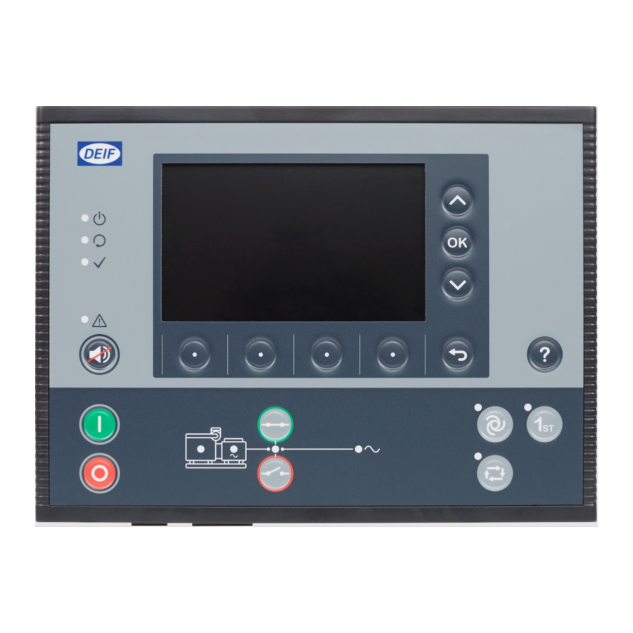
About the display unit (DU 300) 2.2.1 Display, LEDs, and buttons Switchboard control Home 12:00 Configure Tools Info Log on Alarm Live data Item Notes Display unit power Off : Unit not powered. Green : Unit powered. Self-check OK Off : Controller self-check not OK, or no Green : Controller self-check OK. -
Page 11: Screen Layout
2.2.2 Screen layout Ready for operation Home 12:00 Configure Tools Info Log on Alarm Live data Item Notes Status text Shows the status of the controller. Symbols Shows information as symbols: Active alarms in system. Logged on user. P# shows genset priority (only GENSET controllers). Path Shows the path for the selected page. -
Page 12: About The Virtual Keyboard
2.2.3 About the virtual keyboard The display unit features several virtual keyboards to enter information or settings. Switchboard control Home / Configure / IO configuration / Terminals / Status 12:00 Digital output 1 Aa#1 Write Item Notes Text input Shows the text, numbers, or value entered. Virtual keyboard Shows keyboard layout selected. -
Page 13: About The Help
2.2.4 About the help View help for any page by selecting Help button Switchboard control Home / Help 12:00 Home menu The Home menu provides access to all of the different features or menus of the controller. INFO Features of the controller are protected by group and user permissions. Some features may be read only or not visible, depending upon the user profile logged on to the controller. -
Page 14: Operating The System
3. Operating the system GENSET controller basic actions 3.1.1 Introduction to operating the GENSET controllers Normal operation The GENSET controllers are usually in AUTO mode. In AUTO mode, the Power Management System (PMS) automatically starts/ stops and connects/disconnects the gensets. The PMS operates with the settings for power requirements and the genset priority. Blackout response When a blackout occurs: •... -
Page 15: Genset Controller Buttons
3.1.2 GENSET controller buttons Item Notes Genset Start genset and start sequence. * Stop genset and stop sequence. * Close breaker : Starts close Breaker Open breaker : Starts open sequence. * sequence. * Options Off : Controller not in AUTO. AUTO mode : Change to AUTO if possible. -
Page 16: Genset Controller Leds
3.1.3 GENSET controller LEDs Item Notes Engine Off : Engine not running or no running feedback. Green flash : Engine start sequence initiated. Green : Running feedback. Oil pressure, RPM, frequency within configured limits. Generator Off : Generator voltage too low to measure. Yellow : Generator voltage and frequency not OK. -
Page 17: Change Modes
3.1.4 Change modes The GENSET controller can operate in PMS control, in AUTO or SEMI mode. The controller can also operate in Switchboard control. The following procedures describe how to change the controller's operating mode and control. Mode Procedure To change to AUTO mode from SEMI mode: 1. -
Page 18: Stop The Genset
Mode Procedure ◦ If needed, to override the Idle run start, push again. Switchboard When the controller is in Switchboard control, the display push-buttons are not available. The genset can only control be started locally and/or from the switchboard. NOTE * Idle run may not be permitted or approved by certain maritime classification societies. -
Page 19: Open The Genset Breaker
Mode Procedure 1. Push to close the genset breaker. a. The PMS synchronises the genset with the busbar (the breaker LED flashes yellow b. When the genset and busbar synchronise, the controller closes the breaker. c. When the breaker is closed, the breaker LED is green •... -
Page 20: Emergency Genset Controller Basic Actions
EMERGENCY genset controller basic actions 3.2.1 Introduction to operating the EMERGENCY genset controller Normal operation The EMERGENCY genset controller is usually in AUTO mode. During normal operation the emergency genset does not run. Blackout response When a blackout occurs: • AUTO mode ◦... -
Page 21: Emergency Genset Controller Buttons
3.2.2 EMERGENCY genset controller buttons Item Notes Genset Start genset and start sequence. Stop genset and stop sequence. Breaker Close breaker : Starts close sequence. Open breaker : Starts open sequence. Tie breaker Close tie breaker : Starts close sequence. Open tie breaker : Starts open sequence. -
Page 22: Emergency Genset Controller Leds
3.2.3 EMERGENCY genset controller LEDs Item Notes Engine Off : Engine not running or no running feedback. Green flash : Engine start sequence initiated. Green : Running feedback. Oil pressure, RPM, frequency within configured limits. Generator Off : Generator voltage too low to measure. Yellow : Generator voltage and frequency not OK. -
Page 23: Change Modes
3.2.4 Change modes The EMERGENCY genset controller can operate in AUTO mode, SEMI mode, or in Switchboard control. The EMERGENCY genset controller can also operate a test sequence. More information Test the EMERGENCY genset for more information. Mode Procedure To change to AUTO mode from SEMI mode: 1. -
Page 24: Stop The Emergency Genset
Mode Procedure • The controller runs the Idle run start sequence. ◦ If needed, to override the Idle run start , push again. Switchboard When the controller is in Switchboard control, the display unit push-buttons are not available. The genset can control only be started locally and/or from the switchboard. -
Page 25: Open The Emergency Genset Breaker
Mode Procedure When the controller is in AUTO mode, the emergency genset breaker is controlled automatically, and the AUTO display unit buttons are disabled. The emergency genset must be running to close the genset breaker. If the emergency genset is not running, push to start the emergency genset. -
Page 26: Open The Tie Breaker
The emergency genset breaker and the tie breaker are both closed for an unlimited time when harbour operation is active. The EMERGENCY genset controller display unit has two sets of breaker push-buttons. The push-buttons next to the main busbar are for the tie breaker. Mode Procedure When the controller is in AUTO mode, the tie breaker is controlled automatically, and the display unit buttons are... -
Page 27: Test The Emergency Genset
Mode Procedure If the emergency genset cannot supply the load: • The PMS does not open the tie breaker. • The controller display unit shows an information message. Switchboard When the controller is in Switchboard control, the display unit push-buttons are not available. The tie breaker control can only be opened from the switchboard. -
Page 28: Hybrid Controller Basic Actions
HYBRID controller basic actions 3.3.1 Introduction to operating the HYBRID controllers Normal operation The HYBRID controllers usually operate in AUTO mode. When in AUTO mode, the PMS automatically starts/stops and connects/ disconnects the inverter. The PMS operates with the settings for power requirements and the genset priority. Blackout response When a blackout occurs: •... -
Page 29: Hybrid Controller Buttons
3.3.2 HYBRID controller buttons Item Notes Inverter Start inverter sequence. * Stop inverter sequence. * Close breaker : Starts close Breaker Open breaker : Starts open sequence. * sequence. * Options Off : Controller not in AUTO. AUTO mode : Change to AUTO if possible. -
Page 30: Hybrid Controller Leds
3.3.3 HYBRID controller LEDs Item Notes Power source Off : Power source is not ready or no running feedback. Green : Power source ready. Inverter Off : Inverter voltage too low to measure. Yellow : Inverter voltage and frequency not OK. Cannot close breaker. Green flash : Inverter voltage and frequency OK, V&Hz OK timer still running. -
Page 31: Change Modes
3.3.4 Change modes The HYBRID controller can operate in PMS control in AUTO or SEMI mode. The controller can also operate in Switchboard control. Mode Procedure To change to AUTO mode from SEMI mode: 1. Push AUTO • The LED next to is green when the controller is in AUTO mode. -
Page 32: Stop The Inverter
3.3.6 Stop the inverter Mode Procedure When the controller is in AUTO mode, the inverter stop is controlled automatically and the display buttons are disabled. If the PMS calculates that power is not required, the controller automatically stop the inverter, AUTO according to the PMS priority order. -
Page 33: Set Inverter Start And Stop Priority
Mode Procedure 1. Push • The controller checks the inverter breaker open sequence. ◦ If the conditions are OK: a. The PMS calculates if the available power is sufficient after the inverter breaker opens. ◦ If not, the PMS prevents the inverter breaker to open, and the controller display shows an information message. -
Page 34: Shaft Generator Controller Basic Actions
SHAFT generator controller basic actions 3.4.1 Introduction to operating the SHAFT generator controller Normal operation The SHAFT generator controller usually operates in PMS control. Blackout response When a blackout occurs: • The PMS automatically follows the blackout recovery sequence to start the gensets and restore power. •... -
Page 35: Shaft Generator Controller Leds And Buttons
3.4.2 SHAFT generator controller LEDs and buttons SHAFT generator buttons Item Notes Breaker Close breaker : Starts close sequence. * Open breaker : Starts open sequence. * NOTE * In Switchboard control the controller ignores the input. SHAFT generator LEDs Item Notes Shaft... -
Page 36: Close The Shaft Generator Breaker
3.4.3 Close the shaft generator breaker When you close the shaft generator breaker, the PMS transfers the load from the gensets to the shaft generator. The shaft generator must therefore be running and have enough capacity to take over the genset load. Control Procedure To close the shaft generator breaker:... -
Page 37: Shore Connection Controller Basic Actions
SHORE connection controller basic actions 3.5.1 Introduction to operating the SHORE connection controller Normal operation The SHORE connection controller usually operates in Power Management System (PMS) control. Blackout response When a blackout occurs: • The PMS automatically follows the blackout recovery sequence to start the gensets restore power. •... -
Page 38: Shore Connection Controller Leds And Buttons
3.5.2 SHORE connection controller LEDs and buttons SHORE connection buttons Item Notes Breaker Close breaker : Starts close sequence. * Open breaker : Starts open sequence. * NOTE * In Switchboard control the controller ignores the input. SHORE connection LEDs Item Notes Shore... -
Page 39: Close The Shore Connection Breaker
3.5.3 Close the shore connection breaker When you close the shore connection breaker, the PMS transfers the load from the gensets to the shore connection. The shore connection must therefore be live and have enough capacity to take over the genset load. Control Procedure To close the shore connection breaker:... - Page 40 Control Procedure ◦ Trip: ◦ The PMS checks if the breaker can be opened without de-loading. ◦ If the conditions are met, the breaker opens. ◦ If the conditions are not met, the controller displays an information message. ◦ Cancel: ◦...
-
Page 41: Bus Tie Breaker Controller Basic Actions
BUS TIE breaker controller basic actions 3.6.1 Introduction to operating the BUS TIE breaker controller Normal operation The BUS TIE breaker controller usually operates in Power Management System (PMS) control. Blackout response When a blackout occurs: • The PMS automatically follows the blackout recovery sequence to restore power. •... -
Page 42: Bus Tie Breaker Controller Leds And Buttons
3.6.2 BUS TIE breaker controller LEDs and buttons BUS TIE breaker buttons Item Notes Breaker Close breaker : Starts close sequence. * Open breaker : Starts open sequence. * NOTE * In Switchboard control the controller ignores the input. BUS TIE breaker LEDs Item Notes Busbar A... -
Page 43: Close The Bus Tie Breaker
3.6.3 Close the bus tie breaker When the bus tie breaker closes, the busbar reconnects. The busbar acts as one busbar, and not as two independent busbars. Control Procedure To close the bus tie breaker: 1. Push a. The PMS synchronises busbar A and busbar B (the breaker LED flashes yellow b. -
Page 44: Operator Messages
Operator messages 3.7.1 Controller status texts The controller status texts are shown at the top of the display. The status text shown depends on the type of controller. Not all texts apply for all controller types. Status text * Description Cannot read the controller status. -
Page 45: Operator Information Messages
Status text * Description The remaining time (in seconds) that the EMERGENCY genset controller parallel test is still Parallel test # s active. Precautionary standby A precautionary genset start alarm or input started the genset. Ready for operation All operation conditions are met. Gensets are ready to start and/or breakers are ready to close. A power supply from the shore connection is available, and the shore connection breaker is SC in operation closed. - Page 46 Operator info Additional information In Switchboard control, operator actions cannot be performed from the controller 1st priority not possible in SWBD interfaces. Alarm blocking BTB close A block alarm is active. Clear the alarm before you try to close the bus tie breaker. Alarm blocking engine start A block alarm is active.
- Page 47 Operator info Additional information Engine start blocked The Block engine start function is active. A stopped genset cannot be started. In Switchboard control, operator actions cannot be performed from the controller Engine start not possible in SWBD interfaces. Engine start unblocked The Block engine start function is not active.
- Page 48 Operator info Additional information The shore connection breaker does not open because the load consumed by the Load on SC too high (Ship-to-ship) receiving ship is too high. The shaft generator breaker does not open because the load to drive the propeller is too Load on SG too high (PTH) high.
- Page 49 Operator info Additional information SGB close cancelled The SGB close was cancelled by an SGB open command. In Switchboard control, operator actions cannot be performed from the controller SGB close not possible in SWBD interfaces. SGB close unblocked The Block shaft generator breaker close function is not active. SGB is closed The Shaft generator breaker is closed.
-
Page 50: Home 4.1 Home Page
4. Home Home page Switchboard control Home 12:00 Configure Tools Info Log on Alarm Live data Item Notes Log on as a user or change the logged on user. Log on page Shows the configure menu. Configure menu Shows the tools menu. Tools menu Shows the information menu. -
Page 51: Log On
5. Log on Log on page Switchboard control Home / Log on 12:00 Select user to log on User Group Admin Administrators Operator Operators Service Service engineers Designer Designers Restart Log off User info Item Notes User list Shows a list of available users on the controller. Logged on user : Shows the user is currently logged on. -
Page 52: Configure
6. Configure Configure page Switchboard control Home / Configure 12:00 Date and time View design Pair Priority Counters Parameters Input/Output Item Notes Shows the priority of any controller in the system. Priority page Configure the date and time settings. Date and time page Configure the views shown on the Live data page. -
Page 53: Date And Time Page
Date and time page Date and time settings cannot be changed if a network time server (NTP) is configured. Switchboard control Home / Configure / Date and time 12:00 Date and time settings Date and time Time 00:41:26 Date 2020-09-01 Time zone Etc/UTC Time format... -
Page 54: View Design Page
View design page Switchboard control Home / Configure / View design 12:00 Select view or add new view View 1 View 2 View 3 View 4 View 5 View 6 View 7 View 8 View 9 View 10 Delete Rename Move Item Notes... -
Page 55: Add Or Configure A View
6.3.1 Add or configure a view Add a view 1. Select Add. 2. Select the template: • Summary information is shown under the preview: Switchboard control Home / Configure / View design 12:00 Select template View 14 4 values; 1 column, 1 gauge •... - Page 56 • 7. Select Write to add the view. Delete a view 1. Highlight the view to delete. 2. Select Delete. 3. Confirm deletion of the view. Rename view 1. Highlight the view to rename. 2. Select Rename. 3. Rename the view as required. 4.
-
Page 57: Pair Page
Pair page Switchboard control Home / Configure / Pair 12:00 Pair Label Host name Hops DG 4 deif-ml300-017928 DG 3 deif-ml300-017900 EDG 2 deif-ml300-015100 EDG 1 deif-ml300-016700 Refresh Item Notes Shows the list of available controllers you can connect. List of available controllers Select OK to pair to the controller. -
Page 58: Priority Page
Priority page View the priorities for all the gensets in the system, not just the GENSET controllers. The genset priorities apply to the whole system, not just a section. The EMERGENCY genset controller is not included in the priority list: •... -
Page 59: Counters Page
Counters page Switchboard control Home / Configure / Counters 12:00 Counters Name Value Engine Start attempts Total Since reset Faults Operation time Generator Breakers Reset Item Notes Counters list Shows the list groups and counters. Shows the highlighted counter to view, edit, or reset. Highlighted counter Select OK to edit the counter value. -
Page 60: Parameters
Parameters 6.7.1 Parameters list page Parameter settings are organised in groups and sub-groups. Open a group or sub-group to select a parameter to configure. Switchboard control Home / Configure / Parameters 12:00 Parameter list Engine Generator Busbar AC setup Voltage transformer Primary 400 V AC Secondary... -
Page 61: Configure A Curve
6.7.2 Configure a curve Curves can only be configured if the curve function is assigned in the input/output configuration. When a curve function is assigned, the parameter is shown in the parameter list. Example Function assigned to an analogue input (AI): Engine >... -
Page 62: Input/Output
Input/output 6.8.1 About input/output The controller inputs and outputs are configurable but depend on the single-line diagram, parameters, functions and alarms. You can configure digital or analogue inputs and outputs, custom alarms, and use functions. More information See the Data sheet, or Hardware characteristics and configuration in the Designer's handbook for more information about the hardware modules and terminals. - Page 63 For each analogue input use, the table below shows which pages in the analogue input view you must configure. Table 6.1 Configuration for the uses of an analogue input Functions Sensor setup Alarms Analogue functions Required Required Optional Digital functions Required Required Optional...
-
Page 64: Rack Or Ecu Selection Page
6.8.2 Rack or ECU selection page The selection is only shown if the system has extension racks or an ECU configured. Switchboard control Home / Configure / IO configuration 12:00 Modules Controller rack 1 / 2 PSM3.1 PSM3.1 ACM3.1 IOM3.1 EIM3.1 GAM3.1 IOM3.1... -
Page 65: Module Selection Page
6.8.3 Module selection page Switchboard control Home / Configure / IO configuration 12:00 IOM3.1, Slot 3 Controller rack Relay output PSM3.1 ACM3.1 IOM3.1 EIM3.1 GAM3.1 IOM3.1 PCM3.1 Digital input CAN-A CAN-B CAN-A CAN-B Item Notes Rack Shows the selected rack. Shows the selected module. -
Page 66: Terminal Selection Page
6.8.4 Terminal selection page Switchboard control Home / Configure / IO configuration / Terminals 12:00 Terminals State/Value Terminal(s) Name Type Func Alarm 1, 2, 3 GB close 4, 5, 6 GB open 7, 8, 9 Digital output 3 10, 11, 12 Digital output 4 13, 23 GB opened... -
Page 67: Digital Input (Di) Page
6.8.5 Digital input (DI) page Switchboard control Home / Configure / IO configuration / Terminals / Status 12:00 Slot#3 Terminal#13, 23 Name Function/Alarm GB open Function Activate ramp 1 Function Reset GOV to offset Function Digital custom alarm Alarm I/O name Functions Alarm Item... -
Page 68: Digital Output (Do) Page
6.8.6 Digital output (DO) page Switchboard control Home / Configure / IO configuration / Terminals / Status 12:00 Slot#3 Terminal#4, 5, 6 Name Function/Alarm In AUTO mode Function Relay I/O name Functions Alarm Item Notes Module and terminal selected Shows the slot number and terminal numbers. Function or alarm list * Shows a list of configured function or alarms on this terminal. -
Page 69: Analogue Input (Ai) Page
6.8.7 Analogue input (AI) page Switchboard control Home / Configure / IO configuration / Terminals / Status 12:00 Slot#3 Terminal#18, 19 Name Function/Alarm Derate 1 temperature [°C] Function Sensor I/O name Functions Alarm Item Notes Module and terminal selected Shows the slot number and terminal numbers. Functions or alarms list Shows a list of all configured functions or alarms on this terminal. -
Page 70: Analogue Output (Ao Or Pwm) Page
6.8.8 Analogue output (AO or PWM) page Switchboard control Home / Configure / IO configuration / Terminals / Status 12:00 Slot#3 Terminal#14, 15 Name Function/Alarm Generator | L1-N [V AC] Function Output setup I/O name Functions Item Notes Module and terminal selected Shows the slot number and terminal numbers. -
Page 71: Alarms
7. Alarms Alarms page Switchboard control Home / Alarms 12:00 Alarms Time Name Value Set point Latch Auto 11:25:18 Voltage or frequency not OK 06:26:56 Generator under-voltage 1 0.00 % 95.00 % 06:25:01 EIM3.1 1 supply voltage low ... 18.00 V ... 06:24:42 Generator under-frequency 1 0.00 %... -
Page 72: Alarm State
7.1.1 Alarm state Alarm Alarm Symbol Acknowledge Notes condition * action ** • An alarm condition occurred. • An alarm action is active. Active Active Unacknowledged • An alarm requires acknowledgement. • An alarm requires action to clear the alarm condition. •... -
Page 73: Remove From Service
• The alarm is marked as shelved ( ) in the alarm list. • The alarm action (protection) is inactive until the alarm is unshelved. Unshelve an alarm 1. Select the shelved alarm. 2. On the details page, select Service. 3. - Page 74 More information See Alarms, Horn outputs in the Designer's handbook for more information about these outputs. OPERATOR'S MANUAL 4189340910Q EN Page 74 of 103...
-
Page 75: Tools
8. Tools Tools page Switchboard control Home / Tools 12:00 Tags Restore Backup Regulator status Units Communication Advanced Item Notes Show or hide Tags. Tags page Restore a backup to the controller. Restore page Create a backup of the controller. Backup page Shows the Advanced menu. -
Page 76: Tags Page
Tags page Switchboard control Home / Tools / Tags 12:00 Tags Name Value Alarm pop-up Alarms Parameters Write Item Notes List of tags Shows a list of areas that tags can be displayed on. Select OK to toggle selection. Tag selection Not selected : The tag is not shown. -
Page 77: Backup Page
Backup page Switchboard control Home / Tools / Backup 12:00 Backup Backup name ID 4 DG 1 Backup location Save to controller Clear Create backup Item Notes Shows the slot number and terminal numbers. Backup name Highlight and select OK to configure the name. Shows the location where the backup is created. -
Page 78: Restore
Restore 8.4.1 Restore restrictions Controller prerequisites Before you restore a backup to a controller, the controller must meet these prerequisites: Controller type Prerequisites GENSET controller 1. The breaker must be opened. 2. The engine must be stopped. EMERGENCY genset controller 3. -
Page 79: Restore Page
8.4.2 Restore page Switchboard control Home / Tools / Restore 12:00 Restore Name Creation date Location ID 4 SG 1.backup 2018-09-11 03:25:42 SD card ID 9 DG 1.backup 2020-07-15 22:53:36 Controller Delete Info Item Notes List of backups Shows the backups on the controller or SD card. Not compatible backup * Shows a not compatible backup in dark grey. -
Page 80: Restore Selection Page
8.4.3 Restore selection page Switchboard control Home / Tools / Restore 12:00 Restore selections Restore IP address (IPv4) and controller ID Restore counters Restore Item Notes List of features Shows a list of features you can restored. Select OK to choose the restore selections. Feature selection Not selected : The feature is not restored. -
Page 81: Regulator Status
Regulator status 8.5.1 Regulator status AVR page Switchboard control Home / Tools / Regulator status 12:00 AVR status AVR selected regulation mode Voltage regulation AVR active regulation mode Voltage regulation AVR regulator source Nominal AVR regulator manual input Not active AVR regulator external offset AVR set point 400 V AC... -
Page 82: Regulator Status Gov Page
8.5.2 Regulator status GOV page Switchboard control Home / Tools / Regulator status Home / Tools / Regulator status 12:00 GOV status GOV selected regulation mode Frequency regulation GOV active regulation mode Frequency regulation GOV regulator source Nominal GOV regulator manual input Not active GOV regulator external offset GOV set point... -
Page 83: Units Page
Units page Switchboard control Home / Tools / Units 12:00 Unit category Name Unit Temperature °C Pressure Item Notes Units list Shows the units you can configure. Selected unit Select OK to configure the unit setting. Unit setting Shows the current unit of measure. OPERATOR'S MANUAL 4189340910Q EN Page 83 of 103... -
Page 84: Communication
Communication 8.7.1 Controller communication page Switchboard control Home / Tools / Communication 12:00 Controller communication Name Value Controller ID fe80::226:77ff:fe01:7928 IPv6 address DG 1 Label 10.10.103.2 DNS preferred 10.10.103.3 DNS alternate Static IP address mode 10.10.103.100 IPv4 address 255.255.255.0 Subnet mask 10.10.103.1 Default gateway Identify... -
Page 85: Display Communication Page
8.7.2 Display communication page Switchboard control Home / Tools / Communication 12:00 Display unit communication Name Value fe80::226:77ff:fe02:6878 IPv6 address 10.10.103.2 DNS preferred 10.10.103.3 DNS alternate 10.10.103.2 IP address mode IP address 10.10.103.105 255.255.255.0 Subnet mask 10.10.103.1 Default gateway Controller Write Item Notes... -
Page 86: Tools - Advanced
9. Tools - Advanced Tools advanced page Switchboard control Home / Tools / Advanced 12:00 Lamp test Change type Brightness Permissions Item Notes Run a lamp test of the display LEDs. Lamp test page Change the controller type. Change type page Shows the brightness menu. -
Page 87: Controller Type Page
Controller type changes are restricted, depending on the initial controller type. An EMERGENCY genset and GENSET controller, can be changed in the field to any PPM 300 controller type. But a SHAFT generator, SHORE connection and BUS TIE breaker controller can only be changed to one of these three controller types. -
Page 88: Brightness Page
Brightness page Switchboard control Home / Tools / Advanced / Brightness 12:00 Restore Brightness level Brightness time Item Notes Change the brightness level settings. Brightness level page Change the brightness time settings. Brightness time page OPERATOR'S MANUAL 4189340910Q EN Page 88 of 103... -
Page 89: Brightness Level Page
9.3.1 Brightness level page Switchboard control Home / Tools / Advanced / Brightness / Level 12:00 Brightness level 25 % 50 % (default) 75 % Write Item Notes Brightness level list Shows a list of the brightness levels in % the display is adjusted to. Select OK to choose the brightness level: Selected level... -
Page 90: Brightness Time Page
9.3.2 Brightness time page Switchboard control Home / Tools / Advanced / Brightness / Timeout 12:00 Brightness time 3 min (default) 5 min 10 min 15 min 30 min 60 min 180 min Write Item Notes Brightness time list Shows a list of times in minutes before the display automatically adjusts the brightness level. Select OK to choose the brightness time: Selected time... -
Page 91: Permissions Page
Permissions page Switchboard control Home / Tools / Advanced / Permissions 12:00 Restore Groups Users Item Notes Shows the groups page. Groups page Shows the users page. Users page OPERATOR'S MANUAL 4189340910Q EN Page 91 of 103... -
Page 92: Groups Page
9.4.1 Groups page Switchboard control Home / Tools / Advanced / Permissions / Groups 12:00 Groups Name Users Last log on Created Display 2014-07-17 Operators 2020-09-03 02:17:50 2014-07-17 Service engineers 2018-12-23 04:46:35 2014-07-17 Designers 2014-07-17 Administrators 2020-09-02 13:36:55 2014-07-17 Item Notes Shows the permission groups. -
Page 93: Users Page
9.4.2 Users page Switchboard control Home / Tools / Advanced / Permissions / Users 12:00 Users Name Group Last log on Created Admin Administrators 2020-09-01 12:22:11 2014-07-17 Operator Operators 2020-09-03 02:17:50 2014-07-17 Service Service engineers 2018-12-23 04:46:35 2014-07-17 Designer Designers 2014-07-17 Item Notes... -
Page 94: Log
12:00 Time Event name 11:25:18 2020-09-02 EIM3.1 1 supply voltage low or missing 02:23:12 2020-09-01 DEIF network redundancy broken 01:56:01 2020-09-01 EIM3.1 1 supply voltage low or missing 17:24:42 2020-08-31 Value changed event 14:17:32 2020-08-31 Busbar voltage and frequency OK... -
Page 95: Dm2 Log Page
10.2 DM2 Log page Switchboard control Home / Log / DM2 log 12:00 DM2 Log (ECU) SPN description Engine speed Engine oil pressure Engine oil temperature Engine coolant temperature Coolant level Fuel delivery pressure Engine intake manifold 1 temperature Battery potential voltage switched 158 16 Engine oil level Clear... -
Page 96: Info 11.1 Info Page
11. Info 11.1 Info page Switchboard control Home / Info 12:00 Versions About Item Notes Shows version information for controller and display, including firmware versions. Versions page This information can be helpful for technical support. Shows information about the controller, including IP address information. About page OPERATOR'S MANUAL 4189340910Q EN Page 96 of 103... -
Page 97: Live Data
12. Live data 12.1 Live data page Switchboard control 1 /13 Home / Live data 12:00 Generator | Total Generator | L1 24.9 Frequency Generator | L1 36.4 Generator | L1-L2 399.4 49.94 V AC Generator | L1 49.94 Home Item Notes Live data information page... -
Page 98: Visual Synchronisation Page
12.2 Visual synchronisation page Switchboard control 9 /13 Home / Live data 12:00 Generator | L1-L2 Busbar | L1-L2 V AC V AC Generator | L2-L3 Busbar | L2-L3 V AC V AC -149° Generator | L3-L1 Busbar | L3-L1 V AC V AC Generator | L1... -
Page 99: Troubleshooting
13. Troubleshooting 13.1 Troubleshooting the system in Switchboard control The exact procedure for operating the system in Switchboard control depends on your switchboard design. Follow the guidelines from the switchboard supplier. Class societies require a certain amount of protections included in the switchboard. For example, there must be a synchronisation check before closing a breaker. -
Page 100: Troubleshooting Analogue Input Sensor Failures
1. Install a redundant DEIF network connection (see Wiring the communication in the Installation instructions). 2. Disable the DEIF network redundancy alarm. The system never had a redundant DEIF network Set the alarm to Not enabled in the parameter: connection. Configure > Parameters >... -
Page 101: Replace Internal Battery
14. Replace internal battery 14.1 Replace battery in PCM3.1 The controller has a replaceable battery in the PCM3.1 module. A battery failure alarm is activated, when the battery power is low. To replace the battery, you need to remove the PCM module. The battery in PCM3.1 is a CR2430 3V battery, rated for operation at -40 to 85 °C (-40 to 185 °F). - Page 102 b. Make sure that the hardware module is the right way up, and slide it back into slot 7. c. Tighten the screws on the hardware module faceplate with 0.5 N·m (4.4 lb-in) of torque. Date and time settings • After the battery is replaced, the date and time must be set on the controller.
-
Page 103: End-Of-Life
In Europe, the disposal of WEEE is governed by the WEEE directive issued by the European Parliament. DEIF complies with this directive. You must not dispose of WEEE as unsorted municipal waste. Instead, WEEE must be collected separately, to minimise the load on the environment, and to improve the opportunities to recycle, reuse and/or recover the WEEE.
Need help?
Do you have a question about the PPM 300 and is the answer not in the manual?
Questions and answers