Sign In
Upload
Manuals
Brands
Deif Manuals
Power distribution unit
PPM 300
Deif PPM 300 Manuals
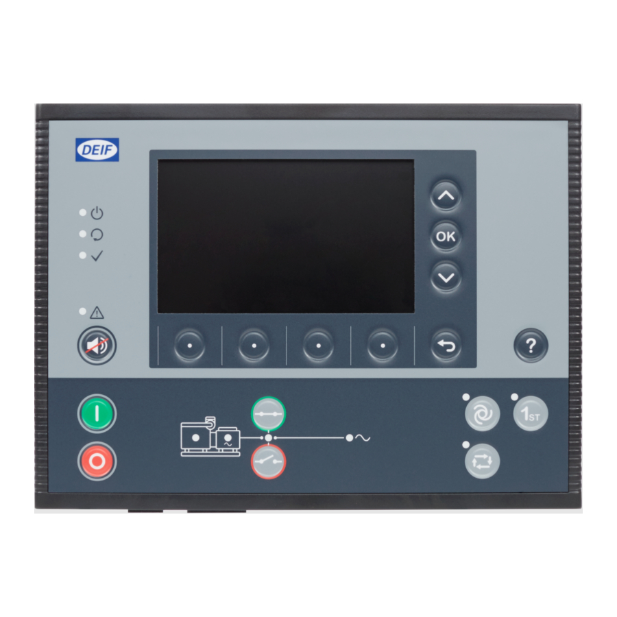
Manuals and User Guides for Deif PPM 300. We have
3
Deif PPM 300 manuals available for free PDF download: Designers Handbook, Operator's Manual
Deif PPM 300 Designers Handbook (521 pages)
Protection and Power Management
Brand:
Deif
| Category:
Power distribution unit
| Size: 4 MB
Table of Contents
Table of Contents
2
About the Designer's Handbook
18
Recommended Design Process
19
Software Versions
20
List of Technical Documentation for PPM 300
21
Warnings and Safety
22
Automatic and Remote-Controlled Starts
23
Legal Information
24
Description
25
2.1 Description
26
Controller Types
26
Understanding the System Versatility
27
Maximum Number of Controllers
30
Priority of Input Sources
31
Power Management System Control
32
Switchboard Control
33
Automatic (AUTO) Mode
37
Semi-Automatic (SEMI) Mode
38
Controller Unpowered
39
Functions
40
AC Configuration
44
Source] and [Busbar] for each Controller Type
46
Busbar] AC Configuration
49
Voltage and Frequency as Digital Outputs
50
Nominal Settings
51
3.2 Nominal Settings
53
Nominal Power Calculations
53
AC Measurements as Analogue Outputs
54
Busbar] AC Measurements
59
Th Current Input
60
Source AC Protections
61
Source] Over-Voltage (ANSI 59)
62
Source] Under-Voltage (ANSI 27)
63
Negative Sequence Voltage (ANSI 47)
64
Zero Sequence Voltage (ANSI 59Uo)
65
Over-Current (ANSI 50TD)
66
Current Unbalance (ANSI 46)
67
Directional Over-Current (ANSI 67)
68
Negative Sequence Current (ANSI 46)
72
Zero Sequence Current (ANSI 51Io)
73
Source] Over-Frequency (ANSI 81O)
74
Overload (ANSI 32)
75
Reverse Power (ANSI 32R)
76
Reactive Power Import (ANSI 40U)
77
Synchronisation Check, Including Blackout Close (ANSI 25)
79
3.5 Busbar AC Protections
80
Busbar] Under-Voltage (ANSI 27)
80
Busbar] Voltage Unbalance (ANSI 47)
81
Busbar] Over-Frequency (ANSI 81O)
82
Busbar] Under-Frequency (ANSI 81U)
83
Other AC Protections
84
Earth Inverse Time Over-Current (ANSI 51G)
85
Neutral Inverse Time Over-Current (ANSI 51N)
86
ACM Voltage Measurement Errors
87
Source]/[Busbar] L# Wire Break
88
3.8 ACM Module General Protections
89
ACM 1 Data Is Missing
89
Introduction
90
4.1 Introduction
92
Alarm Levels
92
Operate Time
93
Alarm Parameters
94
Set Point
96
Delay
99
Inhibit(S)
100
Auto Acknowledge
101
Additional Alarm Information
102
4.3 Customised Inhibits
103
Suppress Action Inhibit
103
4.4 Alarm Handling
105
Acknowledge
105
Shelve
106
Out of Service
107
Latch Reset
108
Alarm Test and Status
109
Alarm Status Digital Outputs
110
Horn Outputs
111
Silencing Alarms
116
4.7 Non-Essential Loads
117
Non-Essential Load Trip (NEL) Function
117
NEL # Over-Current
121
NEL # Overload
122
NEL # Reactive Overload
123
4.8 Input Alarms
124
Analogue Input (AI) Alarms
124
Miscellaneous Alarms
125
4.9 Miscellaneous Alarms
126
Critical Process Error
126
Priority Error
127
Advanced Blackout Prevention
128
Calculating the Load Sharing Error
131
P Load Sharing Failure (Low Frequency) on DG
132
P Load Sharing Failure (High Frequency) on DG
133
Q Load Sharing Failure (Low Voltage) on DG
134
Q Load Sharing Failure (High Voltage) on DG
135
Reverse Power on DG
136
Reactive Power Import on DG
137
18.5 Change Controller Type
139
Introduction
139
Regulation Required for De-Loading
140
Synchronisation under Switchboard Control
141
Configuring Breakers
142
Compact Breaker
145
Continuous Breaker
147
Redundant Breaker Feedback
150
Short Circuit, and Short Circuit Close Attempts
151
Synchronisation Functions
152
Static Synchronisation
156
Regulator Synchronisation Parameters
159
Synchronisation and Breaker Alarms
160
De-Load Failure
161
Vector Mismatch
162
Breaker Closing Failure
163
Breaker Trip (External)
164
Phase Sequence Error
165
Breaker Configuration Failure
166
Any Bus Tie Breaker Position Failure
167
2.3 Control and Modes
168
Introduction
168
Relay Regulation
171
Regulation Mode Overview
173
Governor Regulation Modes
175
Frequency Synchronisation
176
Power Load Sharing
177
Governor Stand-Alone Mode
178
AVR Regulation Modes
180
Reactive Power Regulation
181
Reactive Power Load Sharing
182
AVR Stand-Alone Mode
183
External Communication
185
External Communication Using Modbus
188
Governor
190
6.5 Governor
192
Governor Analogue Regulation Function
192
Governor Relay Regulation Function
194
Automatic Voltage Regulator
196
AVR Analogue Regulation Function
198
AVR Relay Regulation Parameters
200
Configuration Alarms
201
AVR Output Selection Failure
202
Regulation Alarms
203
6.8 Regulation Alarms
204
AVR Regulation Error
204
P Load Sharing Failure
205
Power Management Principles
207
Power Management Functions
209
Busbar Sections
211
Ring Busbar Connection
212
Local Power Management
213
Section Power Management
214
System Power Management
216
Managing Missing Controllers
217
7.2 Connected, Consumed and Available Power
220
Power Reservation
220
Power Analogue Outputs
221
Genset Priority
222
Priority Selection Method
223
Dynamic Genset Priority
224
Running Hours for Genset Priority
225
Genset Priority Digital Outputs
226
Genset Start and Stop
227
7.4 Genset Start and Stop
228
Load-Dependent Start Configuration
228
Load-Dependent Start Flowchart
230
Load-Dependent Stop Configuration
231
Load-Dependent Stop Flowchart
234
Power Method and Hysteresis
235
Percent Method for Load-Dependent Start and Stop
236
Percent Method and Hysteresis
237
Non-Connected Genset
238
Precautionary Genset Start
239
Number of Gensets Connected
241
9.8 Other EMERGENCY Genset Controller Functions
242
Blackout
242
7.5 Blackout
243
Blackout Recovery Configuration
243
Blackout Recovery Flowchart
245
Load Sharing
246
Equal Load Sharing
247
Asymmetric Q Load Sharing
254
SHAFT Generator Base Load
257
SHORE Connection Base Load
259
DEIF Network Load Sharing Failure
260
7.7 Heavy Consumer Management
261
Configuring Heavy Consumers
261
Heavy Consumer Sequence
264
Heavy Consumer Flowcharts and Example
266
Fast Load-Reduction
268
Protections
269
7.8 Externally Controlled Breakers
271
Externally Controlled Shore Connection
271
Power Management Alarms
273
7.9 Power Management Alarms
274
Blackout Detection Mismatch
274
Heavy Consumer Feedback Timeout
275
Missing Controller ID
276
Forced to Switchboard Control
277
DEIF Network Redundancy Broken
278
Different Power Management Rules Activated
279
GENSET Controller Overview
280
GENSET Controller Principles
282
Run Coil or Stop Coil
283
Running Detection
284
Regulation
287
Load Sharing
288
8.3 Engine Start
291
Engine Start Flowchart
291
Engine Start Sequence
292
Interruption of the Start Sequence
295
8.4 Engine Stop
297
Engine Stop Flowchart
297
Engine Shutdown Flowchart
299
Generator Breaker Close Flowchart
300
Generator Breaker Blackout Close
301
Generator Breaker Open Flowchart
302
Generator Breaker Trip Flowchart
303
Other GENSET Controller Functions
304
Temperature-Dependent Power Derating
305
Engine Operating Values as Analogue Outputs
306
Counters
307
Trip AVR
308
Alarm Actions
310
Breaker Alarms
311
Emergency Stop
313
Underspeed
314
Primary Running Feedback Failure
315
Start Enable Removed During Start
316
Engine Stopped (External)
317
Trip Running Hours Notification
318
DG-SG Max. Parallel Time
319
EMERGENCY Genset Controller Overview
321
EMERGENCY Genset Controller Principles
323
EMERGENCY Genset Controller Nominal Settings
324
Running Detection
325
9.3 Engine Start
326
Engine Stop
326
Generator Breaker Close Flowchart
327
Generator Breaker Open Flowchart
328
Generator Breaker Trip Flowchart
329
Tie Breaker Open Flowchart
330
Tie Breaker Trip Flowchart
331
Emergency Genset Test Functions
332
Engine Test
333
Parallel Test
334
Load Take-Over Test
335
Emergency Genset Configurations
336
Emergency Genset as Part of the System
337
Main Busbar Is OK
339
Harbour Operation
342
Parallel Timers
345
Temperature-Dependent Start/Stop
346
EMERGENCY Genset Controller Protections
347
Alarm Actions
348
Breaker Alarms
349
AC Alarms
350
Non-Essential Loads
351
Emergency-Main Busbar Maximum Parallel Time
352
SHAFT Generator Controller Overview
353
SHAFT Generator Controller Principles
354
Nominal Settings
355
AC Configuration
356
Shaft Generator Breaker Open Flowchart
358
Shaft Generator Breaker Blackout Close Flowchart
359
Shaft Generator Breaker Trip Flowchart
360
Other SHAFT Generator Controller Functions
361
Shaft Generator Base Load
365
Shaft Generator Load Transfer Without Parallel
366
Temperature-Dependent Power Derating
367
Engine States as Digital Outputs
368
12.4 Other BUS TIE Breaker Controller Functions
370
Counters
370
Trip AVR
371
Alarm Actions
372
Breaker Alarms
373
AC Alarms
374
SG-DG Max. Parallel Time
375
Overspeed
376
SHORE Connection Controller Overview
377
SHORE Connection Controller Principles
378
Power Management
379
Shore Connection Breaker
380
Shore Connection Breaker Close Flowchart
381
Shore Connection Breaker Open Flowchart
383
Shore Connection Breaker Blackout Close Flowchart
385
Shore Connection Breaker Trip Flowchart
386
Other SHORE Connection Controller Functions
387
Shore Connection Base Load
390
Sensitive Shore Connection (Overlap)
392
Shore Connection Load Transfer Without Parallel
393
Counters
394
SHORE Connection Controller Protections
395
Alarm Actions
396
AC Alarms
397
SC-DG Max. Parallel Time
398
SC-SC Max. Parallel Time
399
BUS TIE Breaker Controller Overview
400
BUS TIE Breaker Controller Principles
401
Nominal Settings
402
AC Configuration
403
12.3 BUS TIE Breaker Controller Sequences
404
Connecting Busbar Sections
404
Bus Tie Breaker Blackout Close
406
Bus Tie Breaker Trip Flowchart
407
BUS TIE Breaker Controller Protections
409
Breaker Alarms
410
Overview
412
Power Supply Characteristics
413
Relay Output Characteristics and Configuration
414
Digital Input Characteristics and Configuration
417
Analogue Input Characteristics and Configuration
418
Analogue Output Characteristics and Configuration
421
Power Supply Module PSM3.1
423
PSM3.1 Terminal Overview
424
Frame Ground Characteristics
425
Power Supply Voltage as an Analogue Output
426
Power Supply Module PSM3.2
427
PSM3.2 Terminal Overview
428
Frame Ground Characteristics
429
PSM3.2 1 Supply Voltage High Alarm
430
Alternating Current Module ACM3.1
431
ACM3.1 Terminal Overview
433
Voltage Measurement Characteristics
434
13.6 Alternating Current Module ACM3.2
436
ACM3.2 Terminal Overview
436
Current Measurement Characteristics
437
13.7 Input/Output Module IOM3.1
438
IOM3.1 Terminal Overview
438
Changeover Relay Output Characteristics
439
13.8 Input/Output Module IOM3.4
441
IOM3.4 Terminal Overview
441
Transistor Output Characteristics and Configuration
442
Digital Input Characteristics
443
13.9 Engine Interface Module EIM3.1
446
EIM3.1 Terminal Overview
446
Power Supply Characteristics
447
Auxiliary Power Supply Voltage as an Analogue Output
448
W Input Characteristics
449
Magnetic Pickup Wire Break
450
Relay Output Characteristics
451
Governor and AVR Module GAM3.1
452
GAM3.1 Terminal Overview
454
Analogue Input (AI) Characteristics
455
Relay Output Characteristics
456
13.11 Governor and AVR Module GAM3.2
459
GAM3.2 Terminal Overview
459
Power Supply Characteristics
460
Pulse Width Modulation (PWM) Output Characteristics
461
Digital Input Characteristics
462
Processor and Communication Module PCM3.1
463
PCM3.1 Terminal Overview
464
PCM3.1 Clock Battery
465
13.13 Display Unit du 300
469
Display Unit Terminal Overview
469
Frame Ground Characteristics
470
13.14 DEIF Ethernet Network
471
Communication Information
471
Restrictions
472
13.15 DEIF Internal Communication
473
Fieldbus Conflict
473
18.3 Log
474
Overview
474
20. Appendix: Pre-Configured Curves
475
Overview
475
Activating Controller Outputs
476
Overview
477
Modbus in the Controller
478
Controller Identifier
479
Modbus Tables
480
Specific Modbus Function Groups
481
Setting up Modbus
484
Date and Time
485
Setting the Time Manually
486
Permissions
487
Group Settings
489
User Settings
490
Default Users
491
Overview
495
Miscellaneous
496
Alive
497
Restrictions
498
Terms and Abbreviations
500
Units
506
Symbols
507
Controller and Component Symbols
508
Flowchart Symbols
511
Overview
513
20.3 Analogue Input Pressure Curves
514
Datcon 7
514
VDO Pressure CU
515
Pt100
516
Pt1000
517
Vdo 40-120
518
VDO Temperature CU
519
To 100 %) to (-10 to 10 V)
520
Advertisement
Deif PPM 300 Operator's Manual (103 pages)
Protection and Power Management
Brand:
Deif
| Category:
Controller
| Size: 2 MB
Table of Contents
Table of Contents
2
About the Operator's Manual
5
Symbols for General Notes
5
Symbols for Hazard Statements
5
Symbols for Leds
5
Intended Users of the Operator's Manual
6
Software Versions
6
Technical Support
6
Warnings and Safety
7
Legal Information
7
Getting Started
9
About Controller Operation
9
About the Display Unit (du 300)
10
Display, Leds, and Buttons
10
Screen Layout
11
About the Virtual Keyboard
12
About the Help
13
Operating the System
14
GENSET Controller Basic Actions
14
Introduction to Operating the GENSET Controllers
14
GENSET Controller Buttons
15
GENSET Controller Leds
16
Change Modes
17
Start the Genset
17
Stop the Genset
18
Close the Genset Breaker
18
Open the Genset Breaker
19
Set Genset Start and Stop Priority
19
EMERGENCY Genset Controller Basic Actions
20
Introduction to Operating the EMERGENCY Genset Controller
20
EMERGENCY Genset Controller Buttons
21
EMERGENCY Genset Controller Leds
22
Change Modes
23
Start the Emergency Genset
23
Stop the Emergency Genset
24
Close the Emergency Genset Breaker
24
Open the Emergency Genset Breaker
25
Close the Tie Breaker
25
Open the Tie Breaker
26
Test the EMERGENCY Genset
27
Harbour Operation
27
HYBRID Controller Basic Actions
28
Introduction to Operating the HYBRID Controllers
28
HYBRID Controller Buttons
29
HYBRID Controller Leds
30
Change Modes
31
Start the Inverter
31
Stop the Inverter
32
Close the Inverter Breaker
32
Open the Inverter Breaker
32
Set Inverter Start and Stop Priority
33
SHAFT Generator Controller Basic Actions
34
Introduction to Operating the SHAFT Generator Controller
34
SHAFT Generator Controller Leds and Buttons
35
Close the Shaft Generator Breaker
36
Open the Shaft Generator Breaker
36
SHORE Connection Controller Basic Actions
37
Introduction to Operating the SHORE Connection Controller
37
SHORE Connection Controller Leds and Buttons
38
Close the Shore Connection Breaker
39
Open the Shore Connection Breaker
39
BUS TIE Breaker Controller Basic Actions
41
Introduction to Operating the BUS TIE Breaker Controller
41
BUS TIE Breaker Controller Leds and Buttons
42
Close the Bus Tie Breaker
43
Open the Bus Tie Breaker
43
Operator Messages
44
Controller Status Texts
44
Operator Information Messages
45
Home 4.1 Home Page
50
Log on
51
Log on Page
51
Configure
52
Configure Page
52
Date and Time Page
53
View Design Page
54
Add or Configure a View
55
Pair Page
57
Priority Page
58
Counters Page
59
Parameters
60
Parameters List Page
60
Configure a Curve
61
Input/Output
62
About Input/Output
62
Rack or ECU Selection Page
64
Module Selection Page
65
Terminal Selection Page
66
Digital Input (DI) Page
67
Digital Output (DO) Page
68
Analogue Input (AI) Page
69
Analogue Output (AO or PWM) Page
70
Alarms
71
Alarms Page
71
Alarm State
72
Shelved Alarms
72
Remove from Service
73
Silence Horn
73
Tools
75
Tools Page
75
Tags Page
76
Backup Page
77
Restore
78
Restore Restrictions
78
Restore Page
79
Restore Selection Page
80
Regulator Status
81
Regulator Status AVR Page
81
Regulator Status GOV Page
82
Units Page
83
Communication
84
Controller Communication Page
84
Display Communication Page
85
Tools - Advanced
86
Tools Advanced Page
86
Controller Type Page
87
Brightness Page
88
Brightness Level Page
89
Brightness Time Page
90
Permissions Page
91
Groups Page
92
Users Page
93
Log
94
Log Page
94
DM2 Log Page
95
Info 11.1 Info Page
96
Live Data
97
Live Data Page
97
Visual Synchronisation Page
98
Troubleshooting
99
Troubleshooting the System in Switchboard Control
99
Troubleshooting Alarms
99
Troubleshooting Analogue Input Sensor Failures
100
Troubleshooting Communication
100
Replace Internal Battery
101
Replace Battery in PCM3.1
101
End-Of-Life
103
Disposal of Waste Electrical and Electronic Equipment
103
Deif PPM 300 Operator's Manual (94 pages)
Protection and Power Management
Brand:
Deif
| Category:
Control Systems
| Size: 1 MB
Table of Contents
Table of Contents
2
1 About the Operator's Manual
5
Intended Users of the Operator's Manual
5
Software Versions
5
Symbols for General Notes
5
Technical Support
5
Warnings and Safety
6
Legal Information
7
2 Getting Started
8
About Controller Operation
8
About the Display Unit (du 300)
9
Display, Leds, and Buttons
9
GENSET Controller Buttons
10
GENSET Controller Leds
11
EMERGENCY Genset Controller Buttons
12
EMERGENCY Genset Controller Leds
13
HYBRID Controller Buttons
14
HYBRID Controller Leds
15
SHAFT Generator Controller Leds and Buttons
15
SHORE Connection Controller Leds and Buttons
17
BUS TIE Breaker Controller Leds and Buttons
18
Screen Layout
19
About the Virtual Keyboard
20
About the Help
21
3 Operating the System
22
GENSET Controller Basic Actions
22
Introduction to Operating the GENSET Controllers
22
Change Modes
22
Start the Genset
23
Stop the Genset
23
Close the Genset Breaker
24
Open the Genset Breaker
24
Set Genset Start and Stop Priority
24
EMERGENCY Genset Controller Basic Actions
25
Introduction to Operating the EMERGENCY Genset Controller
25
Change Modes
25
Start the Emergency Genset
26
Stop the Emergency Genset
26
Close the Emergency Genset Breaker
27
Open the Emergency Genset Breaker
27
Close the Tie Breaker
28
Open the Tie Breaker
28
Test the Emergency Genset
29
Harbour Operation
29
HYBRID Controller Basic Actions
30
Introduction to Operating the HYBRID Controllers
30
Change Modes
30
Start the Inverter
31
Stop the Inverter
31
Close the Inverter Breaker
31
Open the Inverter Breaker
32
Set Inverter Start and Stop Priority
32
SHAFT Generator Controller Basic Actions
33
Introduction to Operating the SHAFT Generator Controller
33
Close the Shaft Generator Breaker
33
Open the Shaft Generator Breaker
33
SHORE Connection Controller Basic Actions
34
Introduction to Operating the SHORE Connection Controller
34
Close the Shore Connection Breaker
34
Open the Shore Connection Breaker
35
BUS TIE Breaker Controller Basic Actions
35
Introduction to Operating the BUS TIE Breaker Controller
35
Close the Bus Tie Breaker
36
Open the Bus Tie Breaker
36
Operator Messages
37
Controller Status Texts
37
Operator Information Messages
38
4 Home 4.1 Home Page
43
5 Log on
44
Log on Page
44
6 Configure
45
Configure Page
45
Date and Time Page
46
View Design Page
47
Add or Configure a View
48
Pair Page
50
Priority Page
51
Counters Page
52
Parameters
53
Parameters List Page
53
Parameters Page
54
Configure a Curve
55
Input/Output
56
About Input/Output
56
Rack or ECU Selection Page
58
Module Selection Page
59
Terminal Selection Page
60
Digital Input (DI) Page
61
Digital Output (DO) Page
62
Analogue Input (AI) Page
63
Analogue Output (AO or PWM) Page
64
7 Alarms
65
Alarms Page
65
Alarm State
66
Shelved Alarms
66
Remove from Service
67
Silence Horn
67
8 Tools 8.1 Tools Page
68
Backup Page
69
Restore
70
Restore Restrictions
70
Restore Page
71
Restore Selection Page
72
Regulator Status
72
Regulator Status AVR Page
72
Regulator Status GOV Page
74
Units Page
75
Communication
76
Controller Communication Page
76
Display Communication Page
77
9 Tools - Advanced
78
Tools Advanced Page
78
Controller Type Page
79
Brightness Page
80
Brightness Level Page
81
Brightness Time Page
82
Permissions Page
83
Groups Page
84
Users Page
85
10 Log
86
Log Page
86
DM2 Log Page
87
11 Info 11.1 Info Page
88
12 Live Data
89
Live Data Page
89
Visual Synchronisation Page
90
13 Troubleshooting
91
Troubleshooting the System under Switchboard Control
91
Troubleshooting Alarms
91
Troubleshooting Analogue Input Sensor Failures
92
Troubleshooting Communication
92
14 Replace Internal Battery
93
Replace Battery in PCM3.1
93
15 End-Of-Life
94
Disposal of Waste Electrical and Electronic Equipment
94
Advertisement
Advertisement
Related Products
Deif PPU-2
Deif PPM
Deif PICUS PPM 300
Deif PPM-3
Deif PPU-3
Deif PPU
Deif PPU 300
Deif GPU 300
Deif Categories
Controller
Measuring Instruments
Control Unit
Monitor
Control Systems
More Deif Manuals
Login
Sign In
OR
Sign in with Facebook
Sign in with Google
Upload manual
Upload from disk
Upload from URL