Table of Contents
Advertisement
Quick Links
Manufactured by:
Backyard Discovery
3305 Airport Drive, Pittsburg, KS 66762
800-856-4445
Basepoint Business Centre: Rivermead Drive,Westlea, Swindon SN5 7EX Phone: 0800-118-2476
J.P. Coenstraat 7, The Bridge, The Hague, 2595 WP, Netherlands Phone: 08005678990
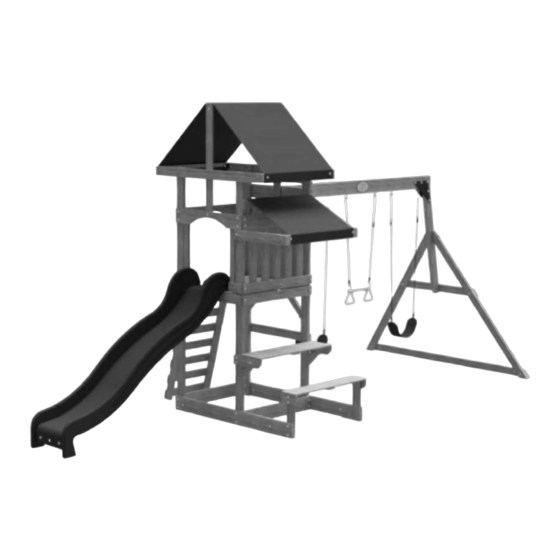
BELMONT
SWING SET
MODEL: # 2001039
WARNING
Adult Assembly Required.
The assembly manual must be retained since it contains important information
Not suitable for children under 36 months due to small parts.
FOR DOMESTIC USE ONLY. INTENDED FOR OUTDOOR USE.
For the most up to date assembly manual, to register your product, or to order replacement parts
Please visit www.backyarddiscovery.com
Para obtener instrucciones en español, visite www.backyarddiscovery.com
EASY STEP-BY-STEP
3D INTERACTIVE INSTRUCTIONS
DOWNLOAD THE FREE APP
INSTALLATION
SERVICES
AVAILABLE!
*
See inside for details
Made in China
INS-2001039-A-BELMONT-ENG 7-1-21
Advertisement
Table of Contents

Subscribe to Our Youtube Channel
Related Manuals for Backyard Discovery BELMONT 2001039


Summary of Contents for Backyard Discovery BELMONT 2001039
- Page 1 Manufactured by: Backyard Discovery 3305 Airport Drive, Pittsburg, KS 66762 800-856-4445 Basepoint Business Centre: Rivermead Drive,Westlea, Swindon SN5 7EX Phone: 0800-118-2476 J.P. Coenstraat 7, The Bridge, The Hague, 2595 WP, Netherlands Phone: 08005678990 BELMONT SWING SET MODEL: # 2001039 WARNING Adult Assembly Required.
- Page 2 INSTALLATION SERVICES AVAILABLE! Need a helping hand? Let our team of professionals handle the installation for you! *Installation services are only available to U.S. customers. With Go Configure, we bring you 18 years of experience right to your doorstep. We service a wide array of indoor and outdoor recreation products that most consumers don’t have the time or ability to deliver &...
- Page 3 Owner’s Manual Please Read This Before Starting Assembly MISSING A PART? CALL US BEFORE GOING BACK TO THE STORE Th e store where you made your purchase does not stock parts for this item. If you have assembly questions or you are missing or have damaged parts, please call 1-800-856-4445 you can also visit www.backyarddiscovery.com...
- Page 4 All wood carries a five (5) year warranty against rot and decay from the original purchase date. Backyard Discovery Metal Play Structure Backyard Discovery warrants this metal play product to be free from defects in materials and workmanship for a period of five (5) years from the original date of purchase. General Warranty Information This warranty applies to the original owner and registrant and is non-transferable.
- Page 5 Owner’s Manual Operating Instructions and Safety Warnings WARNING: BURN HAZARD • Pay special attention to plastic and metal surfaces as they may be hot enough to cause burns. • Always check the temperature of the product before NOTE: letting your children play on it. •...
- Page 6 Owner’s Manual Please Read This Before Starting Assembly Positioning Your Playcenter Suggested Playground Surfacing • Th e playcenter is designed to be installed on a level • Do not install home playground equipment over surface by an adult with an adult helper. Place concrete, asphalt, packed earth, grass, carpet, or any in a fl at area of your yard to minimize ground other hard surface.
- Page 7 Owner’s Manual Please Read This Before Starting Assembly APPENDIX A The following information is from the United States X3.1.3.2 Do not install loose-fi ll surfacing over hard surfaces such as concrete or asphalt. Consumer Product Safety Commission’s Information X3.1.4 Poured-In-Place Surfaces or Pre-Manufactured Sheet for playground surfacing material;...
- Page 8 • Check all moving parts including swing seats, Backyard Discovery assumes no responsibility or ropes, cables, and chains for wear, rust, or other liability for any charge incurred by the Customer for deterioration.
- Page 9 About Our Wood Backyard Discovery uses 100% Cedar (C. Lanceolata) wood. Although we take great care in selecting the best quality lumber available, wood is still a product of nature and susceptible to weathering which can change the appearance of your set.
- Page 10 Owner’s Manual Assembly Tips Protrusion Hazard Incorrect Correct If you see exposed threads and your bolt protrudes beyond the T-Nut you may have over tightened the bolt or used incorrect hardware. If you’ve overtightened, remove the bolt and add washers to eliminate the protrusion.
- Page 11 Owner’s Manual Assembly Tips ASSEMBLY TIP: Keep an eye out for these boxes which will contain helpful pictures and information making the assembly process as quick and painless as possible. Sorting Wood When removing the wood from the boxes we recommend arranging them by part number before you begin assembly.
- Page 12 Owner's Manual Tools Required for Installation...
- Page 13 Owner's Manual Basic Setup Dimensions & Assembly Notes Place the set on level ground, not less than 6'-7" [2 m] from any structure or obstruction such as a fence, garage, house, overhanging branches, laundry lines, or electrical wires. • While assembling unit, take time before and after each phase to make sure fort is level. If fort is not level, assembly will be difficult and improper assembly may result.
- Page 14 Parts Identification Owner's Manual Wood Components (Not to Scale) FORT UPRIGHT - W4L13102 1 3/8"x3 3/8"x89 1/2" (36x86x2273) FORT UPRIGHT - W4L13103 1 3/8"x3 3/8"x89 1/2" (36x86x2273) FORT UPRIGHT - W2A03069 1 7/16"x3 3/8"x89 1/2" (36x86x2273) FORT UPRIGHT - W4L13553 1 3/8"x3 3/8"x89 1/2"...
- Page 15 Parts Identification Owner's Manual Wood Components (Not to Scale) FLOOR BRACE - W4L13112 1"x3 3/8"x34 1/8" (24x86x868) PICNIC TARP SUPPORT - W4L13554 1"x3 3/8"x24 1/2" (24x86x622) WALL SLAT - W4L13114 1"x3 3/8"x25 1/2" (24x86x648) PICNIC SUPPORT - W4L13115 1"x3 3/8"x15 1/4" (24x86x387) PICNIC SUPPORT - W4L13116 1"x3 3/8"x13 1/2"...
- Page 16 Parts Identification Owner's Manual Wood Components (Not to Scale) WALL RAIL - W4L13123 5/8"x5 1/4"x34 7/8" (16x134x887) ARCHED WALL RAIL - W4L13124 5/8"x5 1/4"x34 7/8" (16x134x887) ARCHED WALL RAIL - W4L13125 5/8"x5 1/4"x34 1/8" (16x134x868) WALL RAIL - W4L13126 5/8"x5 1/4"x34 1/8" (16x134x868) TARP SUPPORT - W4L13127 5/8"x3 3/8"x40"...
- Page 17 Parts Identification Owner's Manual Wood Components (Not to Scale) PICNIC CLEAT - W4L13134 PICNIC CLEAT - W4L13135 WALL RAIL - W4L13136 5/8"x3 3/8"x10 1/8" (16x86x258) 5/8"x3 3/8"x6 3/4" (16x86x172) 5/8"x3 3/8"x6 1/4" (16x86x160) WALL RAIL - W4L13137 WALL SLAT - W4L13138 WALL RAIL - W4L13139 5/8"x3 3/8"x4 3/4"...
-
Page 18: Table Of Contents
Owner's Manual Parts Identification Hardware Components H100115 BOLT WH H100027 LAG SCREW WH (22) 5/16x1/2 (38) 5/16x2 H100005 NUT BARREL WH (70) 5/16x7/8 H100222 BOLT WH 5/16x3/4 H100028 LAG SCREW WH 5/16x2 1/2 H100004 NUT BARREL WH 5/16 x 5/8 H100008 BOLT WH 5/16x1... - Page 19 Owner's Manual Parts Identification Hardware Components H100088 SCREW PFH (48) 8x1 1/8 H100108 WASHER LOCK INT H100083 SCREW TAPPING 8x15 14x3/4 H100087 SCREW PFH 8x1 1/4 H100106 WASHER FLAT H100086 SCREW PFH 9x18 (136) 8x1 1/2 H100072 T-NUT H100089 SCREW PFH 8x1 3/4 H100095 WASHER SPLIT...
- Page 20 Owner's Manual Parts Identification Accessory Components (Not to Scale) A100028 HAND GRIP GREEN PLASTIC A100054 SLIDE RAIL 8' GREEN RIGHT A100055 SLIDE RAIL 8' GREEN LEFT A100164 BYD ID TAG (LARGE) AGES 3-10 A100060 CLIMBING ROCK GREEN SMALL A6P00386 SLIDE BED 8' DARK GREEN A100314 "A"...
- Page 21 Owner's Manual Parts Identification Accessory Components (Not to Scale) A6P00382 ROOF TARP A6P00383 PICNIC TABLE TARP A4M00527 GROUND STAKE REBAR...
- Page 22 SLIDE ASSEMBLY STEP 1 SLIDE BRACE - W4L08748 (x1) 5/8"x3 3/8"x17 1/4" (16x86x438) A6P00386 SLIDE BED 8' DARK GREEN (x1) H100115 BOLT WH H100074 T-NUT (x3) (x3) 5/16x1/2 5/16 NOTE: TAKE NOTE OF SLIDE BED SURFACE FINISH, THE DULL SIDE WILL BE TOWARDS THE GROUND. PLACE SLIDE BRACE CENTERED ON THE BOTTOM (DULL SIDE) AND 1/2"...
- Page 23 SLIDE ASSEMBLY STEP 2 A100054 SLIDE RAIL 8' GREEN RIGHT (x1) CENTER SLIDE BRACE - W4L08749 5/8"x3 3/8"x17 1/4" (16x86x438) (x2) A100055 SLIDE RAIL 8' GREEN LEFT (x1) H100090 SCREW PFH (x24) 8x2 1/2" NOTE: USING A 1/8" DRILL BIT, DRILL PILOT HOLES IN EACH INDENTATION ALONG EACH SIDE RAIL. THERE SHOULD BE 12 INDENTIONS ON EACH RAIL.
- Page 24 SWING BEAM STEP 1 ASSEMBLY SB74 SWING BEAM - W4L13423 2"x5 1/4"x89 1/2" (50x134x2274) TRIANGLE A100294 A100140 L BRACKET PLATE 100° 5 66x66x127 HOLE H100047 BOLT HEX H100105 WASHER FLAT H100110 NUT LOCK 5/16x2 3/4 8x27 5/16 H100011 H100005 BOLT WH NUT BARREL WH 5/16x1 3/4 5/16x7/8...
-
Page 25: Bolt Wh
SWING BEAM STEP 2 ASSEMBLY SWING BEAM SUPPORT - W4L13424 END SUPPORT - W4L13120 2"x3 3/8"x46 1/8" (50x86x1170) 1"x3 1/2"x42" (24x86x1072) GROUND BOARD - W4L13121 ANGLE BRACE - W4L13104 1"x3 3/8"x87 3/8" (24x86x2218) 1 3/8"x3 3/8"x73 1/4" (36x86x1862) H100021 BOLT WH H100014 BOLT WH H100012... - Page 26 SWING BEAM STEP 3 ASSEMBLY (1) SWING BEAM SUBASSEMBLY (1) SWING BEAM END SUBASSEMBLY H100011 BOLT WH H100005 NUT BARREL WH 5/16x1 3/4 5/16x7/8 (x2) BOLT - 1 3/4" (x2) SWING BEAM SUBASSEMBLY NUT BARREL - 7/8" SWING BEAM END SUBASSEMBLY...
- Page 27 SWING BEAM STEP 4 ASSEMBLY H100099 SWING HANGER 5/16x9 1/2 H100103 WASHER SAFETY H100105 WASHER FLAT H100110 NUT LOCK 17x30 8x27 5/16 (x6) NUT - 5/16" (x6) WASHER - 8x27 (x6) WASHER - 17x30 (x6) SWING HANGER - 9 1/2"...
- Page 28 ROCK LADDER STEP 1 ASSEMBLY ROCK BOARD - W4L13140 ROCK WALL SLAT - W4L13421 ROCK WALL RAIL - W4L13119 5/8"x3 3/8"x20 1/4" (16x86x514) 5/8"x3 3/8"x20 1/4" (16x86x514) 1"x3 3/8"x48 3/4" (24x86x1238) H100086 SCREW PFH (32) 8x1 1/2 NOTE: 1. Assemble slats to rails as shown. 2.
-
Page 29: H100001 Bolt Fa
ROCK LADDER STEP 2 ASSEMBLY CLIMBING ROCK A100060 GREEN SMALL H100088 SCREW PFH H100001 BOLT FA H100073 T-NUT 8x1 1/8 3/8x1 1/2 NOTE: 1. Install T-nuts before attaching rocks. 2. Orient top edge of rocks with top edge of slats. 3. -
Page 30: Nut Barrel - 7/8
FORT ASSEMBLY STEP 1 FORT UPRIGHT - W4L13103 ROOF CROSS BRACE - W4L13110 FLOOR JOIST - W4L13111 1 3/8"x3 3/8"x89 1/2" (36x86x2273) 1"x3 3/8"x53 7/8" (24x86x1368) 1"x3 3/8"x34 1/8" (24x86x868) FORT UPRIGHT - W2A03069 WALL RAIL - W4L13422 WALL RAIL - W4L13126 1 7/16"x3 3/8"x89 1/2"... - Page 31 FORT ASSEMBLY STEP 2 FORT UPRIGHT - W4L13102 ARCHED WALL RAIL - W4L13125 1 3/8"x3 3/8"x89 1/2" (36x86x2273) 5/8"x5 1/4"x34 1/8" (16x134x868) FORT UPRIGHT - W4L13553 1 3/8"x3 3/8"x89 1/2" (36x86x2273) GROUND BOARD - W4L13107 ROOF CROSS BRACE - W4L13110 1"x5 1/4"x59 1/2"...
- Page 32 FORT ASSEMBLY STEP 3 WALL RAIL - W4L13139 TARP SUPPORT - W4L13129 WALL RAIL - W4L13123 5/8"x3 3/8"x34 7/8" (16x86x887) 5/8"x3 3/8"x36 3/4" (16x86x935) 5/8"x5 1/4"x34 7/8" (16x134x887) WALL RAIL - W4L13131 FLOOR/TARP SUPPORT - W4L13528 5/8"x3 3/8"x34 7/8" (16x86x887) 5/8"x3 3/8"x34 7/8"...
- Page 33 FORT ASSEMBLY STEP 4 FLOOR JOIST - W4L13111 FLOOR BRACE - W4L13118 1"x3 3/8"x34 1/8" (24x86x868) 1"x3 3/8"x3 3/8" (24x86x86) ANGLE BRACE - W4L13105 1 3/8"x2 3/8"x18 1/8" (36x60x460) FLOOR BRACE - W4L13112 FLOOR JOIST - W4L13527 1"x3 3/8"x34 1/8" (24x86x868) 1"x3 3/8"x34 1/8"...
- Page 34 FORT ASSEMBLY STEP 5 FLOOR BOARD - W4L13128 FLOOR BOARD - W4L13133 5/8"x3 3/8"x36 3/4" (16x86x935) 5/8"x3 3/8"x32 1/8" (16x86x815) H100086 SCREW PFH (60) 8x1 1/2 (x8) FLOOR BOARD (x40) SCREW - 1 1/2" (x2) FLOOR BOARD (x20) SCREW - 1 1/2"...
- Page 35 STEP 6 FORT ASSEMBLY FLOOR JOIST - W4L13111 WALL RAIL - W4L13132 1"x3 3/8"x34 1/8" (24x86x868) 5/8"x3 3/8"x34 7/8" (16x86x887) WALL RAIL - W4L13136 WALL RAIL - W4L13137 5/8"x3 3/8"x6 1/4" (16x86x160) 5/8"x3 3/8"x4 3/4" (16x86x122) H100012 BOLT WH H100027 LAG SCREW WH H100030 WASHER LOCK EXT...
- Page 36 FORT ASSEMBLY STEP 7 WALL SLAT - W4L13114 1"x3 3/8"x25 1/2" (24x86x648) A100053 L BRACKET 54x67 - GRN H100086 SCREW PFH H100083 SCREW TAPPING 8x1 1/2 14x3/4 REPEAT FOR OTHER SIDE (x2) WALL SLAT (x4) SCREW - 1 1/2" (x2) L BRACKET 54x67 - GRN (x4) SCREW - 14x3/4"...
- Page 37 STEP 8 FORT ASSEMBLY WALL SLAT - W4L13138 5/8"x3 3/8"x25 1/4" (16x86x640) H100088 SCREW PFH H100087 SCREW PFH 8x1 1/8 8x1 1/4 (x4) WALL SLAT (x8) SCREW - 1 1/8" (x8) SCREW - 1-1/4"...
- Page 38 STEP 9 FORT ASSEMBLY WALL SLAT - W4L13138 5/8"x3 3/8"x25 1/4" (16x86x640) A100053 L BRACKET 54x67 - GRN WALL SLAT - W4L13122 1"x2 3/8"x25 1/2" (24x60x648) H100086 SCREW PFH H100088 SCREW PFH H100083 SCREW TAPPING 8x1 1/2 (20) 8x1 1/8 14x3/4 (x5) WALL SLAT...
- Page 39 FORT ASSEMBLY 1 1/4 in [33 mm] A4M01046 PICNIC TARP SUPPORT - W4L13554 TARP SUPPORT - W4L13129 L BRACKET 2.5x38x55x55 1"x3 3/8"x24 1/2" (24x86x622) 5/8"x3 3/8"x36 3/4" (16x86x935) H100005 NUT BARREL WH H100012 H100222 H100115 BOLT WH BOLT WH BOLT WH 5/16x7/8 5/16x3/4 5/16x1/2...
- Page 40 STEP 1 1 FORT ASSEMBLY ANGLE BRACE - W4L13106 PICNIC SUPPORT - W4L13116 PICNIC CLEAT - W4L13134 1 3/8"x2 3/8"x12 1/4" (36x60x310) 1"x3 3/8"x13 1/2" (24x86x344) 5/8"x3 3/8"x10 1/8" (16x86x258) FLOOR BOARD - W4L13128 5/8"x3 3/8"x36 3/4" (16x86x935) H100013 H100027 H100030 BOLT WH LAG SCREW WH...
- Page 41 FORT ASSEMBLY STEP 1 2 PICNIC SUPPORT - W4L13109 PICNIC SUPPORT - W4L13117 PICNIC SUPPORT - W4L13115 1"x5 1/4"x5 1/4" (24x134x134) 1"x3 3/8"x6 3/4" (24x86x172) 1"x3 3/8"x15 1/4" (24x86x387) FLOOR BOARD - W4L13128 PICNIC CLEAT - W4L13135 5/8"x3 3/8"x36 3/4" (16x86x935) 5/8"x3 3/8"x6 3/4"...
- Page 42 FORT ASSEMBLY STEP 13 TARP SUPPORT - W4L13127 FLOOR/TARP SUPPORT - W4L13130 5/8"x3 3/8"x40" (16x86x1016) 5/8"x3 3/8"x34 7/8" (16x86x887) A4M01046 L BRACKET 2.5x38x55x55 H100222 H100008 BOLT WH H100030 WASHER LOCK EXT BOLT WH H100005 NUT BARREL WH H100074 T-NUT 5/16x1 8x19 5/16x3/4 5/16x7/8...
- Page 43 FORT ASSEMBLY STEP 14 H100128 SCREW PWH 8x5/8 A6P00382 ROOF TARP (x1) ROOF TARP 1 7/8 in [47 mm] (x6) SCREW - 5/8 REPEAT FOR OTHER SIDE...
- Page 44 FORT ASSEMBLY STEP 15 H100128 SCREW PWH 8x5/8 A6P00383 PICNIC TABLE TARP 1 7/8 in [47 mm] (x6) SCREW - 5/8 (x1) PICNIC TABLE TARP...
- Page 45 STEP 16 FORT ASSEMBLY A100028 HAND GRIP GREEN PLASTIC H100062 H100108 H100106 H100072 BOLT PTH WASHER LOCK INT WASHER FLAT T-NUT 1/4x1 1/4 8x15 9x18 (x2) HAND GRIP GREEN PLASTIC (x4) T-NUT - 1/4" (x4) (x4) BOLT - 1/4x1 1/4" WASHER - 9x18 (x4) WASHER - 8x15...
- Page 46 FORT ASSEMBLY STEP 17 (1) 4 FT ROCK LADDER H100028 LAG SCREW WH H100030 WASHER LOCK EXT 5/16x2 1/2 8x19 Using 'M13' ladder attachment holes as a guide,predrill these edges. 'M13' ladder attachment holes. (x2) (x2) LAG SCREW - 2 1/2" WASHER - 8x19...
- Page 47 FORT ASSEMBLY STEP 18 9208100 8 FT - FLAT PACK SLIDE H100115 H100074 BOLT WH T-NUT 5/16x1/2 5/16 12 3/4 in [324 mm] 9 in [229 mm] 2 3/4 in [70 mm] 1 3/8 in [36 mm] 1 in [25 mm] SLIDE BED DRILLING PATTERN (x3)
- Page 48 FORT ASSEMBLY STEP 19 (1) 4 FT SWING BEAM ASSEMBLY A100164 A100314 BYD ID TAG (LARGE) AGES 3-10 "A" REVISION TAG H100042 BOLT HEX H100095 WASHER SPLIT H100105 WASHER FLAT H100074 T-NUT H100128 SCREW PWH 5/16x1 1/4 5/16 8x27 5/16 8x5/8 NOTE: INSERT T-NUTS BEFORE ATTACHMENT...
- Page 49 FORT ASSEMBLY STEP 20 A6P00034 A100069 A6P00054 QUICK LINK TRAPEZE YELLOW SWING SEAT GREEN 22IN A100083 ROPE-CHAIN GREEN 33" A100087 ROPE-CHAIN GREEN 51.25" INSERT CHAIN ONTO QUICK LINK NOTE: SWING HANGER, THEN TIGHTEN SWING HANGER COUPLING. WHEN HANGING YOUR SWINGS IT IS RECOMMENDED THAT THE BOTTOM OF THE SWING SEAT, WHEN SITTING ON IT,...
- Page 50 FINAL ASSEMBLY STEP 21 A4M00527 H100115 BOLT WH H100005 NUT BARREL WH GROUND STAKE REBAR 5/16x1/2 5/16x7/8 H100031 WASHER LOCK EXT 12x19 NOTE: FAILURE TO USE GROUND STAKES CAN VOID WARRANTY AND CAUSE INJURY! 1. DRIVE REBAR GROUND STAKE INTO THE GROUND AT A 45 °...
Need help?
Do you have a question about the BELMONT 2001039 and is the answer not in the manual?
Questions and answers