
Related Manuals for Badger Meter FMS-3


Summary of Contents for Badger Meter FMS-3
- Page 1 Fluid Management System FMS-3 2.4 GHz RF High-End Software v4.1 User Manual FMS-UM-01491-EN-02 (April 2016)
- Page 2 Fluid Management System, FMS-3 2.4 GHz RF High-End Software v4.1 Page ii FMS-UM-01491-EN-02 April 2016...
-
Page 3: Table Of Contents
User Manual CONTENTS Introduction . . . . . . . . . . . . . . . . . . . . . . . . . . . . . . . . . . . . . . . . . . . . . . . . . . . . . . . . . . . . . . . . . . . . . . . . . 5 System Overview . - Page 4 Fluid Management System, FMS-3 2.4 GHz RF High-End Software v4.1 EPM-3 RF Meter . . . . . . . . . . . . . . . . . . . . . . . . . . . . . . . . . . . . . . . . . . . . . . . . . . . . . . . . . . . . . . . . . . . . . 28 Key Description .
-
Page 5: Introduction
The Badger Meter® Fluid Management System has been designed to control and monitor the consumption and inventory balances of automotive fluid products with minimal installation and programming costs . Badger Meter has used its years of expertise in the automated meter reading market to develop a modular control system using RF communications . -
Page 6: System Overview
Introduction System Overview 1…8 Page 6 FMS-UM-01491-EN-02 April 2016... -
Page 7: System Composition And Dataflow
Introduction System Composition and Dataflow Master Keypad Dispense Keypad 1000 1000 1200 Dispenses Dispenses printer FMS software Host printer RS-232 RS-232 RS-232 RS-232 RS-232 Interface Computer PC FMS Database The main data streams: • The FMS software stores the configuration data into the database . •... -
Page 8: Certification
Wall-Mounting the Keypad Certification • Contains FCC ID: S4GEM35XB • Contains IC: 8735A-EM35XB • FCC CERTIFIED, PART 15, SUB-PART C • CE0681 EC-R&TTE Certified This device complies with Part 15 of the FCC Rules . Operation is subject to the following two conditions: (1) this device may not cause harmful interference, and (2) this device must accept any interference received, including interference that may cause undesired operation . -
Page 9: Keypad Description
Wall-Mounting the Keypad Keypad Description Function Signal Name Pin • PC functions as DTE (Data Terminal Equipment) Received Data Carries data from DCE to DTE • Keypad functions as DCE (Data Communication Equipment) Transmitted Data Carries data from DTE to DCE •... -
Page 10: Operation Modes
Wall-Mounting the Keypad Operation Modes The configuration of the system is generally done using the PC-based FMS Software . Only some special functions like the operation modes are set at the Master Keypad . RF System with PC Operation Mode In this mode the PC is used to configure the system entities and install the network . -
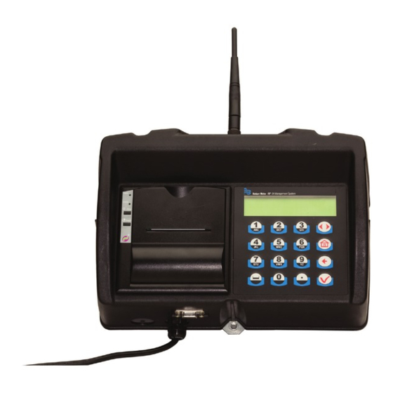
Page 11: Master Keypad
Master Keypad MASTER KEYPAD The Master Keypad acts as the communications director for the RF communications . It handles all communications between the Dispense Keypads and the PC or Host . There are no operator menus associated with the Master Keypad—only supervisor menus for setting up the system or creating reports . -
Page 12: Configuration (Cnf) Menu
Master Keypad Configuration (CNF) Menu Select The CNF menu is used to set the system’s operation modes and archiving methods . INI CNF DK REP Order List If you see the message “Order List Not Empty," you have to clear the transactions in the Master Keypad (CNF Menu) . - Page 13 Master Keypad Work Order Validation WO validation is used to define if a work order shall be validated by the system before processing it . Host Validation (Host Operation Mode) In this mode the work order number will be sent to the ERP (DMS) system . Only after validation from the system the meter will unlock .
-
Page 14: Test Communication (Dk) Menu
Master Keypad Test Communication (DK) Menu Select The DK menu is used to check the communication amongst all keypads . INI CNF DK REP Test All DKs Press Scroll to move the cursor to either YES or NO and press Enter . YES / NO Three Dispense Keypads are set up in the following example . -
Page 15: Reports (Rep) Menu
Master Keypad Reports (REP) Menu • Connect a printer or a PC (Terminal program) to the serial printer port (RS232) . • Settings are 9600 Baud, Data Bits 8, Stop Bits 1, Parity ODD . • Reports will automatically be stored in the data logger (RF memory) at the Master Keypad . OTEE: To use this feature you must the select External Printer Select... -
Page 16: Radio (Rad) Menu
Master Keypad Radio (RAD) Menu The RAD menu screens are: • Address (ADR) toggles the display between the Radio Address and the Radio Prefix screens . • Network (NWK) allows you to select the Radio Network . • Power (PWR) displays the radio’s transmit (Tx) output power . •... - Page 17 Master Keypad Radio Power Select 1 . Press Scroll to move the cursor to PWR . 2 . Press Enter to display the Radio Power Level screen . ADR NWK PWR STA RADIO PWR LEVEL 3 . Press Enter to return to the selection screen . 20 dBm Radio Status The Radio Status options are:...
-
Page 18: Dispense Keypad
Dispense Keypad DISPENSE KEYPAD The Dispense Keypads are responsible for the communication with the RF meters . The user starts a work order from the keypad . After the dispense operation has been completed the keypad will receive the actual amount dispensed from the meter . -
Page 19: Configuration (Cnf) Menu
Dispense Keypad Configuration (CNF) Menu Select The CNF menu is used to set the system’s operation modes and CNF MET REP 190 archiving methods . System Reset Resets the system parameters to the original factory settings . Mileage Type Defines the unit for the Free Alphanumeric field (Defined in Global Keypad Settings) Top Off Timer Specifies the amount of time, how long user can make additional dispenses . -
Page 20: Delete Prepared Wos (Met) Menu
Dispense Keypad Buzzer The buzzer beeps each time you press a button . You can turn off the sound . See Global Keypad Settings . Auto Override Activates the system Auto Override feature in all keypads so users can dispense WOs when the Master Keypad is not operational . -
Page 21: Reports (Rep) Menu
Dispense Keypad Reports (REP) Menu • Connect a printer or a PC (Terminal program) to the serial printer port (RS232) . • Settings are 9600 Baud, Data Bits 8, Stop Bits 1, Parity ODD . • Reports are automatically stored in the data logger (RF-memory) at the Master Keypad . OTEE: To use this feature, you must the select External Printer Select... -
Page 22: Rf Communication Test (Lnk) Menu
Dispense Keypad RF Communication Test (LNK) Menu Select The LNK menu is used to check the quality of the RF communication between the Master and Dispense Keypads . LNK RAD SYS ... The test performs a number of test communications and measures the quantity of lost transmissions . The Link Quality 10 is the maximum you can achieve . - Page 23 Dispense Keypad Radio Network The Radio Network default is zero . You need to change this setting only if you have multiple RF FMS systems . All RF Meter/Hose Radio Network settings must match the Master Keypad and Dispense Keypad settings . Select 1 .
-
Page 24: Network Connect (Con) Menu
Dispense Keypad Network Connect (CON) Menu The Network Connect forces the keypad to connect to a new Master Keypad network . This option is used when: • Replacing the Master Keypad . • Moving the Dispense Keypad if the Dispense Keypad does not automatically find the new network . Select ADR NWK PWR STA Select... -
Page 25: Dispense Keypad Menu Overview
Dispense Keypad Dispense Keypad Menu Overview Enter PIN No. Enter PIN No. Enter WO No. Enter WO No. Enter Hose Enter Hose Quantity Quantity Enter For Enter For ---- ---- ---- ---- Dispense Dispense --------------- --------------- Fluid Fluid Product Name Product Name Supervisor 0000 Supervisor 0001... -
Page 26: Dispense Process
Dispense Process DISPENSE PROCESS Enter PIN No. ---- Enter WO No. Enter Hose 123A2 --------- 02 - Hos e ID First YES / NO Quantity WO Valid Host 3.0 - YES / NO WO Valid. PC YES / NO Enter for Dispense External validation By FMS Software (PC) - Page 27 Dispense Process Meter Selection Enter a preset meter (hose) ID for the product . Enter Hose 5 . Enter a preset meter (hose) ID for the fluid product you want and press Enter . - - - • Only meters that are assigned to the current keypad can be selected . •...
-
Page 28: Key Description
EPM-3 RF Meter EPM-3 RF METER The meter is equipped with RF communications to communicate dispense authorization and result information . Once a work order has been set up, the operator simply pulls the trigger and the authorized amount of fluid for that meter will dispense . The valve will automatically shut off when the full quantity has been dispensed . -
Page 29: Rf Mode (Standard Pre-Selection Mode)
EPM-3 RF Meter RF Mode (Standard Pre-Selection Mode) Work Order Validation via the Dispense Keypad 0.00 When the battery pack is attached to the meter, the meter Dispensed will automatically enter the RF mode . The trigger is in a Quantity locked-out position and no oil can be dispensed until a dispense order is received by the meter . -
Page 30: Auto Mode (Autonomous)
EPM-3 RF Meter AUTO Mode (Autonomous) MPORTANT This function allows unauthorized dispenses. The dispense information will not be associated to any mechanic or operator. • The total dispensed quantity is stored under the general work order number (999999) . • The AUTO sign at the display’s lower left corner indicates the manual mode . -
Page 31: Changing The Battery
EPM-3 RF Meter Changing the Battery When the batteries need changing, a progression of warnings appears on the meter screen . First Warning The Low Battery icon appears in the lower left corner of the display . That means the batteries are low and need to be changed when the icon appears . -
Page 32: Installing The Fms Software
Installing the FMS Software INSTALLING THE FMS SOFTWARE Use the FMS Software for the system configuration . Only some special functions, like the operation modes, are set at the Master Keypad . The software sets work orders and assigns a product and a quantity to it . All dispense results are collected and saved in a work order list (W.O. -
Page 33: Installing The Fms Server
Installing the FMS Software Installing the FMS Server After the prerequisites are installed, the FMS Server Setup Wizard appears: 1 . Click Next . 2 . Select the installation folder you want the Server installed to . The default folder is highly recommended . 3 . - Page 34 Installing the FMS Software 4 . Click Next to confirm the installation . During the installation, a screen similar to this one displays, showing the installation progress: When the installation is complete, a screen similar to this one displays . 5 .
-
Page 35: Installing The Fms Client
Installing the FMS Software Installing the FMS Client 1 . Select Install Client . The Client installs the SQL Compact Edition if it is not installed . 2 . Click Accept . After the prerequisites are installed, the FMS Client Setup Wizard screen appears: 1 . - Page 36 Installing the FMS Software 4 . Click Next to confirm the installation . When the installation is complete, a screen similar to this one displays . 5 . Click Close to exit the installer . Page 36 FMS-UM-01491-EN-02 April 2016...
-
Page 37: Launching The Fms Software
Launching the FMS Software LAUNCHING THE FMS SOFTWARE To launch the software, click on the FMS Client icon on your desktop The screen below displays only if there is an issue with the network connection . You must enter the IP address where the server resides . 1 . -
Page 38: Using The Fms Software
Using the FMS Software USING THE FMS SOFTWARE Setting Up New Users To add a new user: 1 . Click New . The screen displays the New User window . 2 . Enter a user name, new PIN (cannot duplicate any currently used pin number) and assign a role . -
Page 39: Setting Up Tanks And Fluids
Using the FMS Software Setting Up Tanks and Fluids To set up tanks and fluids, click Tanks & Fluids . OTEE: Add Tank, Edit and Delete buttons are disabled when there are pending work orders . Using the software, you can track and monitor tank levels based off work orders . To track this, you first need to add a tank and its corresponding fluid . - Page 40 Using the FMS Software Adding a Tank These are the fields of information required to add a tank: Automatically displays the next available sequential ID number . You can also select available tank IDs Tank ID from the drop-down menu . Sets the units of measurement that you use to track the tank level .
- Page 41 Using the FMS Software Tanks and Fluid Delivery After the tank and fluid(s) are set up, the software displays a graphical representation of the tank level, including: • The Tank ID • The fluid type and ID • The fluid level in units and percentage To change the information, click Edit .
-
Page 42: Setting Up Keypads And Hoses
Using the FMS Software Edit a Fluid Use this feature to edit names and ID numbers of fluids or to delete a fluid . This feature is used with the host settings to match fluid IDs to the Host Protocol Configuration product IDs . To edit a fluid: 1 . - Page 43 Using the FMS Software Global Keypad Settings Make sure your Global Keypad Settings are configured correctly . To change the Global Keypad Settings: 1 . Click the Settings . Dispense Keypad Distance Units Specifies the units (miles or kilometers) of odometer readings for each WO . Numeric Requests that mileage be tracked .
- Page 44 Using the FMS Software Adding a Master Zone 1 . From the Keypad and Hoses screen, click New Master Zone . 2 . Select the Master Zone ID from the drop-down menu . The options are 1…8 . 3 . Select the serial port that the master is plugged into from the COM Port from the drop-down menu .
- Page 45 Using the FMS Software Adding Hoses After adding a keypad, you can add hoses associated with it . You can also enter hoses not associated with any keypad . You can drag and drop hoses to a keypad or between keypads in the system tree . To add hoses: 1 .
-
Page 46: System Settings
Using the FMS Software System Settings To change system settings, click System Settings on the left-hand side . Location Location is set as a factory default and cannot be changed by the user . Select the firmware version your master and Dispense Keypad is using . Version 1x can support Firmware Version 99 meters, version 2x and version 3x for 2 .4 GHz radios can support up to 250 meters . - Page 47 Using the FMS Software Functions Options Log Viewer Use the Log Viewer to display system activity logs based on the parameters you choose . 1 . From the System Settings screen, click Log Viewer . 2 . Check the boxes next to the options you want to display .
- Page 48 Using the FMS Software Email Settings To configure the software to send an email on the completion of a work order or when the fluid level of a tank has reached its warning level, enter the SMTP settings for your email server . Contact your local system administrator for information on your email server .
- Page 49 Using the FMS Software View Host File When the Use Host Settings feature is enabled, the View Host File button appears on the screen . Click View Host File to open the host file editor in a new window . Reset Reverts to the current settings, any unsaved changes are lost .
-
Page 50: Initialize System
Initialize System INITIALIZE SYSTEM Test Comm Option The Test Comm option checks that the serial cable is connected to the Master Keypad and the correct communication port has been selected . 1 . To test the serial communication between the Master Keypad and PC, click Test Comm . -
Page 51: Initialize All
Initialize System Initialize All 1 . Click Initialize All to initialize all parts of the system . Use this option for the first initialization . You are reminded that information currently saved on the keypads will be erased . 2 . Click OK to continue, or Cancel to exit the window and return to the previous screen . The initialization process may take several minutes . -
Page 52: Parts Department User Menu
Parts Department User Menu PARTS DEPARTMENT USER MENU The parts department user can enter work orders, view work order reports and enter a fluid delivery, if enabled . Upon login, the screen to the left displays: Creating a Pending Work Order To enter a new work order: 1 . -
Page 53: Work Order Reports
Parts Department User Menu Work Order Reports To see if a work order has been completed by another user, click W.O. REPORTS . If no work orders have been completed, the screen to the left displays . The default view shows all work orders that have been completed on that day . - Page 54 Parts Department User Menu Locating a Work Order To locate a specific work order, you may search by user, work order ID, hose ID, fluid type and date range . The user, work ID, hose ID, fluid type and date range search options are drop down menu boxes that list unique values in the database .
-
Page 55: Print A Report
Parts Department User Menu Exporting Work Orders to a CSV File To export the data in the current report to a semicolon-separated value (CSV) file: 1 . Click Export . 2 . Select the folder/location that you would like to save the file to and click OK . - Page 56 Parts Department User Menu Adding Fluid to a Tank If this feature is enabled, you can add fluid upon delivery . To add fluid to a tank: 1 . Double-click on the tank or select the tank and click on Fluid Delivery .
-
Page 57: Dispense Keypad Error Messages
Parts Department User Menu TROUBLESHOOTING Dispense Keypad Error Messages These error messages can be displayed by the Dispense Keypad . The associated action to reset the system is listed behind . Message Messages at the Dispense Keypad The selected meter currently has a dispense order in waiting to be processed, complete Hose active hit hose reset the active order . -
Page 58: Worksheets
Worksheets WORKSHEETS Tank ID Units Fluid Capacity Level Maximum: 16 Tanks Tank volume format: 00000 .000 Keypad ID Address xx . xx . xx . xx Maximum: 36 Dispense Keypads RF-Keypad address is an 8-digit number . Page 58 FMS-UM-01491-EN-02 April 2016... - Page 59 Worksheets Meter ID Address x . xxx . xxx . xxx Tank Unit Keypad Maximum: 250 Meters/Hose Meter/ Hose address is a 10-digit number . April 2016 FMS-UM-01491-EN-02 Page 59...
- Page 60 Worksheets User ID Name User PIN ID Role The user field is alphanumeric with a maximum of 16 characters . The user PIN ID is a 4-digit number . Number of Users Allowed: • Supervisor – 1 • Dispense Users – 249 •...
- Page 61 Worksheets INTENTIONAL BLANK PAGE April 2016 FMS-UM-01491-EN-02 Page 61...
- Page 62 INTENTIONAL BLANK PAGE Page 62 FMS-UM-01491-EN-02 April 2016...
- Page 63 INTENTIONAL BLANK PAGE April 2016 FMS-UM-01491-EN-02 Page 63...
- Page 64 The Americas | Badger Meter | 4545 West Brown Deer Rd | PO Box 245036 | Milwaukee, WI 53224-9536 | 800-876-3837 | 414-355-0400 México | Badger Meter de las Americas, S.A. de C.V. | Pedro Luis Ogazón N°32 | Esq. Angelina N°24 | Colonia Guadalupe Inn | CP 01050 | México, DF | México | +52-55-5662-0882...
Need help?
Do you have a question about the FMS-3 and is the answer not in the manual?
Questions and answers