
Related Manuals for Badger Meter F001


Summary of Contents for Badger Meter F001
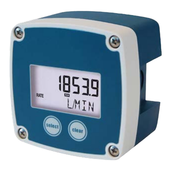
- Page 1 F001 - Basic Flow rate Indicator / Totalizer with analog and pulse signal outputs Installation Manual AC_F001_IA_02_2243 (December 2019)
- Page 2 F001 - Basic Flow rate Indicator / Totalizer with analog and pulse signal outputs Seite II AC_F001_IA_02_2243 December 2019...
-
Page 3: Table Of Contents
3.1. Function of the F001 ........ - Page 4 F001 - Basic Flow rate Indicator / Totalizer with analog and pulse signal outputs 6. Technical specifications ............. . 19 7.
-
Page 5: Basic Safety Recommendation
Basic safety recommendation 1. BASIC SAFETY RECOMMENDATION Before installing or using this product, please read this instruction manual thoroughly. Only qualified personnel should install and/or repair this product. If a fault appears, contact your distributor. Installation Do not place any unit on an unstable surface that may allow it to fall. Never place the units above a radiator or heating unit. -
Page 6: Introduction
Technical specifications. 2.2.2. UNINTENDED USE A hazardous situation may occur if the F001 is not used for purpose it was designed for or is used incorrectly. Please obey the information as given in this instruction manual: • Do not use the standard configuration (safe area / ordinary location applications) in an hazardous area. -
Page 7: General Description
3. GENERAL DESCRIPTION 3.1. Function of the F001 The function ot the F001 is to show the flow rate, the total and the accumulated total as well as to generate a scaled pulse according the accumulated total. 3.2. Component information The F001 has: •... -
Page 8: Setup Menu - Explanation
General description 4. A-OUT mode Output disable - enable r.min Rate min 0.000 - 9999999 r.max Rate max 0.000 - 9999999 t.min Tune min 0 - 9999 t.max Tune max 0 - 9999 5. D-OUT mode Output mode Off; Short; Long decs Decimals 0;... - Page 9 General description Examples Metric The flow meter generates 2.4813 pulses per liter and the selected engineering unit is m³. 1 m³ equals 1,000 liters, therefore per m³, 2,481.300 pulses are generated. The K-Factor is based on the number of pulses generated by the flow meter per selected engineering unit, which gives 2,481.300/m³...
-
Page 10: Navigation
General description WARNING DO NOT TUNE THE OUTPUT IF A PROCESS IS ACTIVE. UNWANTED RESULTS WILL OCCUR IF YOU TUNE THE F001 WHEN THE ANALOG OUTPUT IS IN USE. UNWANTED RESULTS CAN RESULT IN (SERIOUS) DAMAGE TO EQUIPMENT. OTE: If required, you can program the analog output up-side-down. In other words the minimum current represents the 20 mA signal and the maximum current represents the 4 mA signal. -
Page 11: Installation
4. INSTALLATION 4.1. Mechanical installation 4.1.1. INTRODUCTION When you install the F001 make sure: • the F001 is installed free from excessive vibrations; • the F001is protected against severe weather conditions. WARNING ONLY QUALIFIED AND WELL-TRAINED PERSONS WHO ARE FAMILIAR WITH THE MECHANICAL INSTALLATION... -
Page 12: Install The Body
Ask the responsible (safety) staff for permission to lock-out / tag-out a part of the installation or system and to do any required work. Lock-out and Tag-out the F001 and the related system. Make sure, the work area is safe. -
Page 13: Electrical Installation - Coil
Installation 4.3. Electrical installation - Coil 4.3.1. ELECTRICAL CONNECTIONS - COIL Hook up the F001 in accordance with the wiring diagrams. It is possible that not all terminals are used, this depends on the configuration of the installation. Note that sensor supply (4) is only available when an external power supply (9, 10) is connected. -
Page 14: Electrical Installation - Reed
Installation 4.4. Electrical installation - Reed 4.4.1. ELECTRICAL CONNECTIONS - REED Hook up the F001 in accordance with the wiring diagrams. It is possible that not all terminals are used, this depends on the configuration of the installation. Note that sensor supply (4) is only available when an external power supply (9, 10) is connected. -
Page 15: Electrical Installation - Npn
Installation 4.5. Electrical installation - NPN 4.5.1. ELECTRICAL CONNECTIONS - NPN Hook up the F001 in accordance with the wiring diagrams. It is possible that not all terminals are used, this depends on the configuration of the installation. Note that sensor supply (4) is only available when an external power supply (9, 10) is connected. -
Page 16: Electrical Installation - Pnp
Installation 4.6. Electrical installation - PNP 4.6.1. ELECTRICAL CONNECTIONS - PNP Hook up the F001 in accordance with the wiring diagrams. It is possible that not all terminals are used, this depends on the configuration of the installation. Note that sensor supply (4) is only available when an external power supply (9, 10) is connected. -
Page 17: Electrical Installation - Namur
Installation 4.7. Electrical installation - NAMUR 4.7.1. ELECTRICAL CONNECTIONS - NAMUR Hook up the F001 in accordance with the wiring diagrams. It is possible that not all terminals are used, this depends on the configuration of the installation. Note that sensor supply (4) is only available when an external power supply (9, 10) is connected. -
Page 18: Commissioning
5. COMMISSIONING 5.1. Remove the battery tab To apply battery power, remove the battery tab (3). Note that the F001 comes on at battery power. This is normal behavior. Figure 10: Remove the battery tab 5.2. How to setup the totalizer... -
Page 19: How To Setup The Flow Rate
20. When in the main menu: TOTAL, press • The SETUP indicator goes off. The F001 is ready for daily use. and hold the SELECT key, for at least 3 • The RUN indicator comes on. seconds. •... - Page 20 Commissioning Press the SELECT key, to make the • The PROG indicator blinks Press the SELECT key as many times as required selection. continuously. applicable. • You can select the required engineering unit. Short and simultaneously, press the • The PROG indicator goes off. If you do not press the SELECT and CLEAR SELECT and CLEAR key to confirm the key short and simultaneously to confirm,...
- Page 21 29. When in the main menu: RATE, press • The SETUP indicator goes off. The F001 is ready for daily use. and hold the SELECT key, for at least 3 • The RUN indicator comes on. seconds. •...
-
Page 22: How To Set Setup Menu Authorization
Press the SELECT key as many times as parameter. applicable. When in the main menu: OTHER, press • The SETUP indicator goes off. The F001 is ready for daily use. and hold the START key, for at least 3 • The RUN indicator comes on. seconds. •... - Page 23 Technical specifications 6. TECHNICAL SPECIFICATIONS Display Type High intensity transflective numeric and alphanumeric LCD, with white LED backlight Dimensions 2.13” x 1.14” (54 x 29 mm) Digits Seven 0.47” (12 mm) and seven 0.28” (7 mm) digits Refresh rate During operation 8 times/sec, it will automatically switch to 1 time/sec after 30 sec without operation Enclosure Length x Height x Depth 3.63“...
- Page 24 Technical specifications Input parameters Coil 90 mVpp Reed R = 1 MΩ, pull-up; F = 120 Hz R = 100 kΩ, pull-up; F = 6 kHz R = 47 kΩ, pull-down; F = 6 kHz NAMUR R = 820 Ω, pull-down; F = 4 kHz Output parameters - Digital Function To transmit accumulated total...
- Page 25 Default and customized settings 7. DEFAULT AND CUSTOMIZED SETTINGS In this chapter, a table with default settings (DEFAULT) are given. For future reference, we advise to complete the empty columns (CUSTOM) with your own settings and selections. 7.1. Default and customized settings 1.
- Page 26 Default and customized settings v-no Software version nn.nn.nn s-no Serial nr. nnnnnnn Pin code 0000 Backlight Seite 22 AC_F001_IA_02_2243 December 2019...
- Page 27 December 2019 AC_F001_IA_02_2243 Seite 23...
- Page 28 The Americas | Badger Meter | 4545 West Brown Deer Rd | PO Box 245036 | Milwaukee, WI 53224-9536 | 800-876-3837 | 414-355-0400 México | Badger Meter de las Americas, S.A. de C.V. | Pedro Luis Ogazón N°32 | Esq. Angelina N°24 | Colonia Guadalupe Inn | CP 01050 | México, DF | México | +52-55-5662-0882 Europe, Eastern Europe Branch Office (for Poland, Latvia, Lithuania, Estonia, Ukraine, Belarus) | Badger Meter Europe | ul.
Need help?
Do you have a question about the F001 and is the answer not in the manual?
Questions and answers