Advertisement
Installation Instructions
1. INTRODUCTION
The SD- 304C PG2 is a wireless PowerG innovative shock detector with optional magnetic contact and
auxiliary input interfacing with all PowerMaster control panels, version 16 or higher. The SD-304C PG2 fits
windows, doors, walls or roofs and is ideal for residential or commercial installations. It detects and analyzes
gross attacks or a series of low level shocks (up to 10 low level shocks within 30 seconds) and provides early
warning of any attempt of intrusion before a burglar actually breaks-in.
The detector incorporates:
• A shock / vibration piezoelectric sensor.
• Optional reed switch.
Optional auxiliary input to use with installer supplied contacts or other wired devices.
⚫
Installer added-value features:
• Digital display enables fast and easy shock level adjustment
• Full remote configuration from PowerMaster control panel or Monitoring Station saves the need to
physically access the shock detector for configuration
• Remote view of: Low Battery, front and back Tamper, Supervision
• An LED lights whenever alarm or tamper events are reported (the LED does not light while a supervision
message is being transmitted).
2. INSTALLATION
2.1 Mounting
Refer to the Shock Detection Radius, in the Specifications section, according to the surface material used. Install the device in a location where a
strong shock impact is expected. The unit should be mounted on a flat surface and firmly fixed using both mounting screws.
For magnetic contact detection, it is highly recommended to attach the detector to the door or window on the fixed frame and the magnet to the
movable part (door or window). For optimal magnetic sensor activity and better security it is recommended to apply the magnet as close as
possible to the
detector's marked side.
Note: Once the cover is removed, a tamper message is transmitted to the control panel. Subsequent removal of the battery prevents transmission
of "TAMPER RESTORE", leaving the detector in permanent alert. To avoid this, press the tamper switch while you remove the battery.
Caution!
Risk of explosion if battery is replaced by an incorrect type. Dispose of used battery according to manufacturer's instructions.
Attention! The unit has a back tamper switch (optional) under the PCB. As long as the PCB is seated firmly within the base, the switch lever will
be pressed against a special break-away base segment that is loosely connected to the base (Figure 2). Be sure to fasten the break-away
segment to the wall. If the detector unit is forcibly removed from the wall, this segment will break away from the base, causing the tamper switch
to open.
D-304286 SD-304C PG2 Installation Instructions
SD-304C PG2
PowerG, Wireless Shock and Contact detector
with Wired Input
Figure 2. Base with P.C. Board Removed
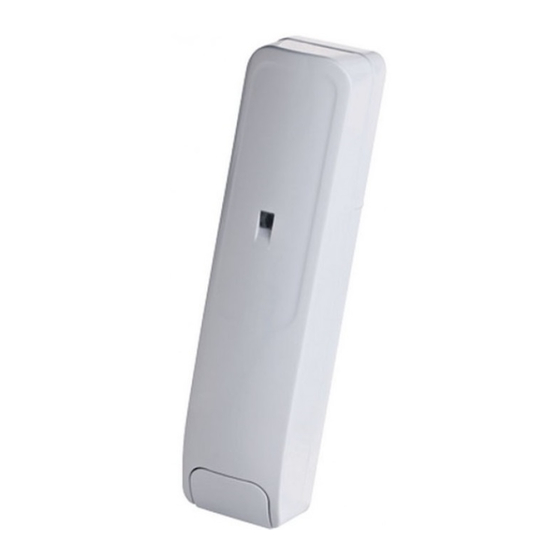
A. Transmission LED
B. Magnet
Figure 1: External View
A. Auxiliary input
terminals
B. Back tamper switch
(behind P.C. board)
C. Battery clips
D. Break-away segment
(for back tamper)
E. Digital display
F. Front tamper switch
G. Enroll button
H. LEDs indication
I. Reed switch
J. Up and down buttons
1
Advertisement
Table of Contents

Related Manuals for Tyco SD-304C PG2


Summary of Contents for Tyco SD-304C PG2
- Page 1 The SD- 304C PG2 is a wireless PowerG innovative shock detector with optional magnetic contact and auxiliary input interfacing with all PowerMaster control panels, version 16 or higher. The SD-304C PG2 fits windows, doors, walls or roofs and is ideal for residential or commercial installations. It detects and analyzes gross attacks or a series of low level shocks (up to 10 low level shocks within 30 seconds) and provides early warning of any attempt of intrusion before a burglar actually breaks-in.
-
Page 2: Auxiliary Input Wiring
Note: Maximal guaranteed cable length is 10m. B. If the auxiliary input of the SD-304C PG2 is defined as a Normally Closed (N.C.) type, series connected N.C. sensor contacts must be used exclusively. An alarm message is transmitted once the loop is opened. -
Page 3: Configuring The Device Parameters
Note: The lower the threshold, the higher the sensitivity, therefore, the lowest thresholds are more suitable for harder materials, such as concrete. 3. While the SD-304C PG2 threshold menu is active, knock on the surface with the required force for the detector to set the required threshold. The power of the detected knock will be presented on the display of the SD-304C PG2 as a blinking number for 3 seconds. -
Page 4: Local Diagnostics Test
USA: CFR 47 part 15 (FCC) Canada: RSS-247, RSS-102 Hereby, Visonic Ltd. declares that the radio equipment type SD-304C PG2 is in compliance with Directive 2014/53/EU. The full text of the EU declaration of conformity is available at the following internet address: http://www.visonic.com/download-center. -
Page 5: Appendix: Specifications
85 % and 95 % non-condensing Auxiliary Input Cable Length 10m max. Auxiliary Input EOL Resistor 2.2 KΩ Dimensions (LxWxD) 118 x 27 x 30 mm (4-5/8 x 1-1/8 x 1-3/16 in.) Weight (including battery) 130g (4.6 oz) D-304286 SD-304C PG2 Installation Instructions... - Page 6 CONSEQUENTIAL OR OTHERWISE, BASED ON A CLAIM THAT THE PRODUCT FAILED TO FUNCTION. EMAIL: info@visonic.com INTERNET: www.visonic.com © 2021 Johnson Controls. All rights reserved. JOHNSON CONTROLS, TYCO and VISONIC are trademarks of Johnson Controls. D-304286 SD-304C PG2 (Rev 13, 02/22) D-304286 SD-304C PG2 Installation Instructions...
Need help?
Do you have a question about the SD-304C PG2 and is the answer not in the manual?
Questions and answers