Table of Contents
Advertisement
Quick Links
Advertisement
Table of Contents

Subscribe to Our Youtube Channel
Related Manuals for Tyco DSC PowerSeries PC1616


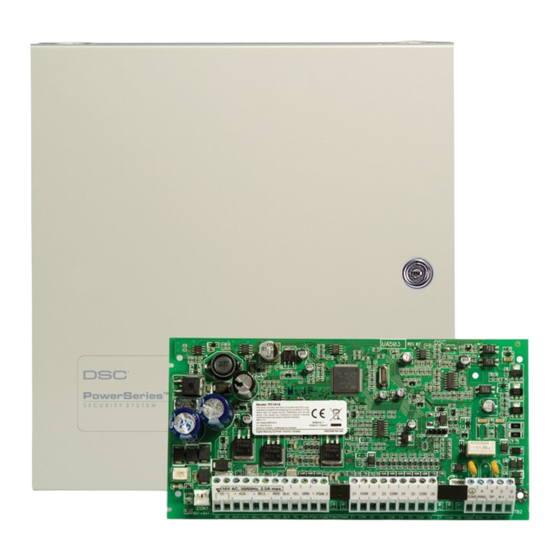
Summary of Contents for Tyco DSC PowerSeries PC1616
- Page 1 PC1616/PC1832/PC1864 v4.5 firealarmresources.com...
- Page 2 firealarmresources.com...
-
Page 3: Table Of Contents
Table of Contents Guidelines for Locating Smoke Detectors and CO Detectors ......ii Section 1 Product Specifications ..........1 Section 2 Installation &... -
Page 4: Guidelines For Locating Smoke Detectors And Co Detectors
PowerSeries - PC1616/PC1832/PC1864 Guidelines for Locating Smoke Detectors and CO Detectors The following information is for general guidance only and it is recommended that local fire codes and regulations be consulted when locating and installing smoke and carbon monoxide alarms. Research indicates that all hostile fires in homes generate smoke to a greater or lesser extent. -
Page 5: Section 1 Product Specifications
Section 1 Product Specifications Section 1 Product Specifications • Supervision for loss of primary power source (AC Fail), battery fail or battery low voltage (Battery Trouble) with indication provided on the keypad • 36 zone types, 12 programmable zone attributes •... -
Page 6: Section 2 Installation & Wiring
PowerSeries - PC1616/PC1832/PC1864 Section 2 Installation & Wiring This Installation Guide provides the basic installation, wiring and programming information required to program the PowerSeries PC1616, PC1832 and PC1864 control panels. This Product is in Conformity with EMC Directive 2004/108/EC based on results using harmonized standards in accordance with article 10(5), R&TTE Directive 1999/5/EC based on Following Annex III of the directive and LVD directive 2006/ 95/EC based on results using Harmonized standards. - Page 7 Section 2 Installation & Wiring 1. Insert Stand off into cabinet 1. Insert Stand off into cabinet PC Board PC Board Stand Off Stand Off mounting hole in the desired location. mounting hole in the desired location. Snap-in-place. Snap-in-place. 2. Position circuit board mounting holes 2.
- Page 8 PowerSeries - PC1616/PC1832/PC1864 The 4-wire KEYBUS (red, black, yellow and green) is the communication connection between the control panel and all modules. The 4 KEYBUS terminals of all modules must be connected to the 4 KEYBUS terminals of the main control panel. The following rules must be followed when wiring the Keybus: •...
- Page 9 Section 2 Installation & Wiring The control panel can provide a maximum of 500mA of current for modules, powered detectors, relays, LED’s etc. If the total current required exceeds 500mA an additional power supply is required (e.g.,PC5200, PC5204). See list below. NOTE: AUX Output voltage: 12VDC, -15%/+10% when Input Voltage is between 85%-110% of rated value and output current between 0.0A - 0.5A max.
- Page 10 PowerSeries - PC1616/PC1832/PC1864 Wire the telephone connection terminals (TIP, Ring, T-1, R-1) to an RJ-31x Connector as indicated. Use 26 AWG wire minimum for wiring. For connec- tion of multiple devices to the telephone line, wire in the sequence indi- cated.
-
Page 11: Section 3 User Commands
Section 3 User Commands Section 3 User Commands Any system keypad can be used to program or perform any keypad command. LED keypads use status and zone indicator lights to represent alarm functions and status. The LCD keypad displays the description and status indicator lights represent alarm functions and status. This section describes basic keypad commands. - Page 12 PowerSeries - PC1616/PC1832/PC1864 Refer to Appendix B – Troubleshooting Guide, for troubleshooting assistance and a detailed description of all trouble conditions. Press [9] to acknowledge and override all existing troubles. Pressing [9] allows the panel to be armed, and will generate and log an override event.
- Page 13 Section 3 User Commands Press [,][6] followed by the Master Code, then press the number corresponding to the following functions. Program Time and Date: Enter the time and date using the following format [HH:MM] [MM/DD/YY]. Program the time using military standard (e.g., 8:00 pm = 20:00 hours). Auto-arm/Auto-disarm Enable/Disable: The keypad will emit 3 rapid beeps if the Auto-arm/disarm feature is now enabled and a steady 2-second tone if it is now disabled.
-
Page 14: Section 4 Programming
PowerSeries - PC1616/PC1832/PC1864 Section 4 Programming This section provides the information necessary to program all required features for a basic system as well as common applications. DSC recommends filling in the Programming Worksheet with the required programming information before programming the system. This will reduce the time required to program and will help eliminate errors. - Page 15 Section 4 Programming Any programming section can be viewed from an LED or LCD5501Z keypad. When a programming section is entered, the keypad will immediately display the first digit of information programmed in that section. The keypad displays the information using a binary format, according to this chart: Press any of the Emergency keys (Fire, Auxiliary or Panic) to advance to the next digit.
-
Page 16: Section 5 Programming Descriptions
PowerSeries - PC1616/PC1832/PC1864 Section 5 Programming Descriptions The following is a brief description of the features and options available in the Power PC1616/1832/1864 control panel. Global Stay Arming When this function key is pressed the panel will prompt the user for an access code. The panel will arm all partitions assigned to that access code in Stay Mode when exit delay expires. - Page 17 Section 5 Programming Descriptions [35] 24-Hour Bell/Buzzer: Instant alarm when violated, system will activate bell output if armed, keypad buzzer if disarmed [36] 24-hour Non-Latching Tamper Zone: Instant tamper condition when violated. Active in both the armed and disarmed state [37] Night Zone: Functions like Interior Stay/Away but will remain bypassed if the user presses [ ][1] to re-activate Stay/Away zones...
- Page 18 PowerSeries - PC1616/PC1832/PC1864 [16] For Future Use [17] Away Armed Status: Activates when all of the selected partitions are armed in Away mode [18] Stay Armed Status: Activates when all of the selected partitions are armed in Stay mode [19] Command Output 1:Activates when a [,][7][1] command is entered on the selected partition –...
- Page 19 Section 5 Programming Descriptions ON: the system will NOT log additional alarms for a zone that has reached the swinger shutdown threshold. OFF: all zone alarms will be logged. ON: Temporal Three Fire Signal is used to annunciate fire alarms (½ second ON, ½ second OFF, ½ second ON, ½ second OFF ½ second ON, 1 ½...
- Page 20 PowerSeries - PC1616/PC1832/PC1864 ON: A valid user code must be entered to restore normal keypad operation after the blanking. OFF: Pressing any key will return the keypad to normal operation. ON: Keypad backlighting enabled. OFF: keypad backlighting disabled. ON: The system temporarily enables the Keypad Blanking feature if an AC failure is detected (to preserve the back up battery). OFF: The system will operate as normal.
- Page 21 Section 5 Programming Descriptions ON: The trouble LED will remain illuminated if the trouble restores before being viewed in the trouble menu. OFF: The trouble LED will be illuminated when a trouble occurs and deactivates when all troubles are restored. ON: When disarming, the keypad will display only the first alarm to occur during the last arming period.
- Page 22 PowerSeries - PC1616/PC1832/PC1864 ON: RF Delinquency Enabled, if any wireless zone supervisory transmission is not received by the PC5132 during a 15-minute period, the PC5132 will place the panel into Not Ready To Arm mode. In the armed state, the Zone faults will generate tamper alarms. The panel will generate a silent trouble (NO trouble beeps but the Trouble LED is turned ON) called “RF Device Delinquency”, that’s only viewable in [,][2] (Trouble Memory).
- Page 23 Section 5 Programming Descriptions [14] ON: Zone requires a normally-closed loop OFF: The zone will follow the End-of-Line configuration in Section [013] [15] ON: Zone requires a single End-of-Line resistor OFF: The zone will follow the EOL configuration in Section [013] [16] ON: Zone requires a double End-of-Line resistors OFF: The zone will follow the End-of-Line configuration in Section [013]...
- Page 24 PowerSeries - PC1616/PC1832/PC1864 Programs the time in minutes the panel will delay activating the bell output when an alarm occurs. If a TLM trouble condition is detected, the Bell Delay Timer will be aborted. Valid entries are [001] to [255]. Programs the time in minutes that the system will postpone automatic arming.
- Page 25 Section 5 Programming Descriptions There is an automatic 2-second pause before additional dial tone searches are initiated. • HEX A is not used. • HEX F represents the end of the phone number (everything after F is ignored). • Pressing [#] in these sections will exit and save the entire phone number. •...
- Page 26 PowerSeries - PC1616/PC1832/PC1864 Delinquency Transmission Delay: Number of hours (Activity Delinquency) or days (Arming Delinquency) the panel will delay before transmitting the event to the central station. Valid entries: [001] to [255]. Communication Cancel Window: Time, in minutes, after an alarm has occurred that the system will report a Communication Cancel reporting event if the system is disarmed.
- Page 27 Section 5 Programming Descriptions ON: The keypad will display the message ‘Communications Cancelled’ (programmable LCD) or ‘CC’ (fixed-message LCD) upon successful transmission of the Communication Cancelled reporting event. OFF: The keypad will not display these messages. ON: The system dials the Call Waiting Cancel String on the first attempt to dial the central station. OFF: The system does not dial the Call Waiting Cancel String.
- Page 28 PowerSeries - PC1616/PC1832/PC1864 Enter the following command to initiate downloading via PC-Link – Section [499] [Installer Code] [499]. Plugging in the PC-Link connec- tor will automatically initiate the connection if DLS is initiated before connecting the PC-Link Header. These Sections are used to customize the operation of the PGM outputs (Section [501] for PGM 1, Section [502] for PGM 2 etc.). The available options depend on which PGM output type is programmed.
- Page 29 Section 5 Programming Descriptions ON: PGM output activates if a a zone is automatically bypassed. ON: PGM output activates if a Medical Alarm occurs. ON: PGM output activates if a confirmed alarms occurs and Police Code occurs. ON: The PGM output is active when the selected condition is true. OFF: The PGM output will latch until a valid user code is entered.
- Page 30 PowerSeries - PC1616/PC1832/PC1864 ON: The system will inhibit arming if a Low Battery or AC trouble condition is present. OFF: Arming will not be inhibited. ON: All Tamper troubles will latch and arming will be inhibited. Enter Installer Programming to clear the trouble condition and return to normal operation.
- Page 31 Section 5 Programming Descriptions Selecting [,][8] [Installer Code] [899] displays the current 5 digit template programming code. Refer to Appendix C - Template Program- ming for a detailed description of available templates and corresponding 5 digit codes. After entering a valid 5 digit template programming code, you will be prompted to enter the following in the sequence below: 1.
- Page 32 PowerSeries - PC1616/PC1832/PC1864 Enter Section [990][Installer Code][990] to enable the Installer Lockout feature. A hardware default cannot be performed when the Installer Lockout feature is ON. In addition, the system will chatter the line seizure relay 10 times if the panel is powered up to indicate the feature is ON.
-
Page 33: Section 6 Programming Worksheets
Section 6 Programming Worksheets Section 6 Programming Worksheets Link Tamper Bell Delay 1-8 Zone Assignment firealarmresources.com... - Page 34 PowerSeries - PC1616/PC1832/PC1864 Programming Worksheets Shaded programming sections indicate minimum programming requirements. Keypad Partition /Slot and Function Key Programming This must be done at each keypad requiring programming. [0] Slot address [Valid entries are 0-8 for the partition, 1-8 for the slot. (e.g., to enroll a keypad in partition 3 and slot 1, enter (31)] [1] Function Key 1 Assignment (Valid entries are 00-32) [2] Function Key 2 Assignment (Valid entries are 00-32) [3] Function Key 3 Assignment (Valid entries are 00-32)
- Page 35 Section 6 Programming Worksheets I _ _ ___I _ ____I I _ ____I _ __ __I I _ _ _ _ _ I _ _ _ _ _ I I _ _ _ _ _ I _ _ _ _ _ I I _ _ ___I _ ____I I _ ____I _ __ __I I _ _ _ _ _ I _ _ _ _ _ I...
- Page 36 PowerSeries - PC1616/PC1832/PC1864 Programmable Output Options Residential Burglary and Fire Bell Output Stay Armed Status Zone Follower Output (Zones 17-24 For Future Use Command Output #1 ([*][7][1]) Zone Follower Output (Zones 25-32) Sensor Reset [*][7][2] Command Output #2 ([*][7][2]) Zone Follower Output (Zones 33-40) 2 Wire Smoke Support (PGM 2 only) Command Output #3 ([*][7][3]) Zone Follower Output (Zones 41-48)
- Page 37 Section 6 Programming Worksheets Normally Closed Loops End-of-line Resistors Double End-of-line Resistors Single End-of-line Resistors Panel shows all Troubles when armed Panel shows only Fire Troubles when armed Tampers/Faults do not show as open Tampers/Faults show as open ...
- Page 38 PowerSeries - PC1616/PC1832/PC1864 WLS Key Does NOT use Access Codes WLS Key Uses Access Codes RF Jam Log after 5 Minutes RF Jam Log after 30 Seconds Audible RF Jam Trouble Beeps Silent RF Jam Trouble Beeps ...
- Page 39 Section 6 Programming Worksheets Access Code Entry Blocked During Entry Delay Access Code Entry Not Blocked During Entry Delay EN Entry Procedure Standard Entry Procedure For Future Use Keyswitch Disarming During Entry Delay Only Keyswitch Disarming at Any Time ...
- Page 40 PowerSeries - PC1616/PC1832/PC1864 Attribute: Audible Steady Chime Bypass Force* Swing Tx. Delay Wireless Zn Silent Pulsed Zone Type: 00 Null Zone 01 Delay 1 02 Delay 2 03 Instant 04 Interior 05 Int. Stay/Away 06 Dly. Stay/Away 07 Dly. 24hr Fire (Hardw.) 08 Stand.
- Page 41 Section 6 Programming Worksheets 19 24hr Water 20 24hr Freeze 21 24hr Latching Tamper 22 Momentary Keyswitch 23 Maintained Keyswitch 25 Interior Delay 26 24hr Non-alarm 29 Auto Verified Fire 30 Fire Supervisory 31 Day Zone 32 Instant Stay/Away 35 24 hr Bell/Buzzer 24 Hr Non-Latching Tamper 37 Night Zone 87 Dly.
- Page 42 PowerSeries - PC1616/PC1832/PC1864 Section Zone # Zone Audible/ Steady/ Chime Bypass Force* Swing Tx. Delay Wireless Cross Type** Silent Pulsed Zn. No [132] I________I I________| I________| I________| I________| I________| I________| I________I I________I [133] I________I I________| I________| I________| I________| I________| I________| I________I I________I [134]...
- Page 43 Section 6 Programming Worksheets System Timers Default 005 Valid entries are 001-005 attempts I_______I_______I_______I Default 040 Valid entries are 001-255 seconds I_______I_______I_______I Default 020 Valid entries are 001-255 seconds I_______I_______I_______I Def 003 Month |_______| _ ______| _ ______| Valid Entries 001-012 Def 005 Week |_______| _ ______| _ ______|...
- Page 44 PowerSeries - PC1616/PC1832/PC1864 No Activity Arming Timers - Default is [000] for all partitions Valid entries are 001-255 minutes, 000 to disable I_______I_______I_______I Valid entries are 001-255 minutes, 000 to disable I_______I_______I_______I Valid entries are 001-255 minutes, 000 to disable I_______I_______I_______I Valid entries are 001-255 minutes, 000 to disable I_______I_______I_______I...
- Page 45 Section 6 Programming Worksheets Communications I___ __I_____I_____I_____I_____I_____I_____I_____I_____I_____I_____I_____I_____I_____I_____I_____I_____I_____I_____I_____I_____I_____I_____I_____I_____I_____I_____I_____I_____I_____I_____I_____I I___ __I_____I_____I_____I_____I_____I_____I_____I_____I_____I_____I_____I_____I_____I_____I_____I_____I_____I_____I_____I_____I_____I_____I_____I_____I_____I_____I_____I_____I_____I_____I_____I I___ __I_____I_____I_____I_____I_____I_____I_____I_____I_____I_____I_____I_____I_____I_____I_____I_____I_____I_____I_____I_____I_____I_____I_____I_____I_____I_____I_____I_____I_____I_____I_____I - This feature is activated in Section [382] Option 4 Default = DB70EF Program unused digits with Hex F I_______I_______I_______I_______I_______I_______I All six digits must be entered for changes to be saved. Fill unused digit spaces with ‘F’. Account Codes Enter a 6-digit account number for the system account code.
- Page 46 PowerSeries - PC1616/PC1832/PC1864 Zone 01 Zone 02 Zone 03 Zone 04 Zone 05 Zone 06 Zone 07 Zone 08 I_______I_______I I_______I_______I I_______I_______I I_______I_______I I_______I_______I I_______I_______I I_______I_______I I_______I_______I Zone 09 Zone 10 Zone 11 Zone 12 Zone 13 Zone 14 Zone 15 Zone 16 I_______I_______I I_______I_______I...
- Page 47 Section 6 Programming Worksheets Zone 01 Zone 02 Zone 03 Zone 04 Zone 05 Zone 06 Zone 07 Zone 08 I_______I_______I I_______I_______I I_______I_______I I_______I_______I I_______I_______I I_______I_______I I_______I_______I I_______I_______I Zone 09 Zone 10 Zone 11 Zone 12 Zone 13 Zone 14 Zone 15 Zone 16 I_______I_______I...
- Page 48 PowerSeries - PC1616/PC1832/PC1864 I_______I_______I For Future Use I_______I_______I For Future Use I_______I_______I For Future Use I_______I_______I For Future Use I_______I_______I For Future Use I_______I_______I Auto Arm Cancellation/Postpone I_______I_______I Special Opening Battery Trouble Alarm Battery Trouble Restoral I_______I_______I I_______I_______I I_______I_______I AC Failure Trouble Alarm I_______I_______I AC Failure Trouble Restoral I_______I_______I...
- Page 49 Section 6 Programming Worksheets Option 1 Option 2 Option 3 Option 4 Option 5 Options 6,7,8 Section Partition 1st Telephone 2nd Telephone Not Used Not Used Alt Comm Future Use Number (Def ON) Number (Def OFF) (Def OFF) (Def OFF) (Def ON) I________I I________I...
- Page 50 PowerSeries - PC1616/PC1832/PC1864 Default Swinger Shutdown (Alarms and Rest)001-014 Transmissions, 000=disabled I_______I______I_______I Swinger Shutdown (Tampers and Rest)001-014 Transmissions, 000=disabled I_______I______I_______I Swinger Shutdown (Maint and Rest)001-014 Transmissions, 000=disabled I_______I______I_______I Communication Delay001-255 seconds, 000=disabled I___ __I__ __I___ __I AC Failure Communication Delay001-255 minutes, 000=disabled I_______I______I_______I TLM Trouble Delay No.
- Page 51 Section 6 Programming Worksheets Contact ID Partial Closing Identifier is “5” Contact ID Partial Closing Identifier is “4” Alarm Communications Enabled During Walk Test Alarm Communications Disabled During Walk Test Communication Cancelled Message Enabled Communication Cancelled Message Disabled ...
- Page 52 PowerSeries - PC1616/PC1832/PC1864 Program only the following attributes for the PGM options listed. All others will be ignored. PGM options are programmed in [009], [010] & [011].PGM Attribute Defaults (Y = Attribute ON; N = Attribute OFF; Blank = Attribute not available): PGM Option [01] Residential Burglary / Fire Bell Output [02] For Future Use...
- Page 53 Section 6 Programming Worksheets Section PGM Output Type* [501] I________I I________| I________| I________| I________| I________| I________| I________I [502] I________I I________| I________| I________| I________| I________| I________| I________I [503] ** I________I I________| I________| I________| I________| I________| I________| I________I [504] ** I________I I________| I________| I________| I________|...
- Page 54 PowerSeries - PC1616/PC1832/PC1864 If a Zone Follower PGM type 29, 35-41 is used, the PGM Output Partition Assignment will be treated as a PGM Output Zone Assign- ment. Each Zone Follower PGM applies to a different bank of zones as in the below table. Record the assignments above. Extended Reporting Codes [601]-[604] Closing (Arming) Reporting Codes, Access Codes 33-95 Code 33...
- Page 55 Section 6 Programming Worksheets Enter a four-digit number (HH:MM) for each day that the system will auto-disarm for each partition (Section [681] for Partition 1 through section [688] for Partition 8). Valid entries are 0000-2359. All entries are disabled (9999) by default. I_______I_______I : I_______I_______I I_______I_______I : I_______I_______I I_______I_______I : I_______I_______I I_______I_______I : I_______I_______I I_______I_______I : I_______I_______I I_______I_______I : I_______I_______I I_______I_______I : I_______I_______I I_______I_______I : I_______I_______I I_______I_______I : I_______I_______I I_______I_______I : I_______I_______I I_______I_______I : I_______I_______I...
- Page 56 PowerSeries - PC1616/PC1832/PC1864 INTERNATIONAL PROGRAMMING Default = 60 Valid Entries 00-99 Seconds 50 Hz AC 60 Hz AC Time Base - Internal Crystal Time Base - AC Line AC/DC Arming Inhibit Enabled AC/DC Arming Inhibit Disabled All System Tampers Require Installer Reset All System Tampers Follow Restore ...
- Page 57 Section 6 Programming Worksheets Special Installer Functions firealarmresources.com...
-
Page 58: Appendix A: Reporting Codes
PowerSeries - PC1616/PC1832/PC1864 Appendix A: Reporting Codes The following tables contain Contact ID and Automatic SIA format reporting codes. For more information on reporting code formats and notes about individual reporting codes. Contact ID The first digit (in parentheses) will automatically be sent by the control. The second two digits are programmed to indicate specific information about the signal. - Page 59 Appendix A: Reporting Codes Table 2: Contact ID Programmed Zone Alarm/Restoral Event Table 3: Automatic Zone Alarm/Restoral Code (as per SIA DCS: ‘Contact ID’ 01-1999): Program any of these codes for zone alarms/restorals when using the standard (non- automatic) Contact ID reporting format. firealarmresources.com...
-
Page 60: Appendix B: Troubleshooting Guide
PowerSeries - PC1616/PC1832/PC1864 Appendix B: Troubleshooting Guide • Power up system • Program options as required (See Programming Section) • Violate, then restore zones • Verify correct Reporting Codes are sent to the Central Station LCD Programmable-Message Keypad • Press [,][2] to view a trouble condition. •... - Page 61 Appendix B: Troubleshooting Guide Trouble Cause Troubleshooting Trouble [1] Service Required Press [1] to determine specific trouble [1] Low Battery Main panel battery less than 11.1VDC NOTE: If battery is new allow 1 Hr. for battery to charge. • Verify voltage measured across AC terminals is 16-18 VAC. NOTE: This trouble condition will not Replace transformer if required.
- Page 62 PowerSeries - PC1616/PC1832/PC1864 Trouble Cause Troubleshooting Trouble [2] AC Failure Trouble [3] Telephone Line Trouble Phone Line Voltage at TIP, RING on • Measure the voltage across TIP and RING on the panel: main panel less than 3VDC • No phone off-hook – 50VDC (approx) •...
- Page 63 Appendix B: Troubleshooting Guide Trouble Cause Troubleshooting Trouble [5] Zone Fault (Cont.) One or more wireless devices have not • If the trouble occurs immediately, a conflict with a hard wired checked in within the programmed time zone exists: • The zone being used is already assigned to a PC5108 zone expander •...
-
Page 64: Appendix C: Template Programming
PowerSeries - PC1616/PC1832/PC1864 Appendix C: Template Programming Template programming allows quick programming of the minimum functions required for basic operation. The below tables are used to determine the desired template to be used ( for information on performing template programming see Section 4 – Pro- gramming Descriptions). - Page 65 Appendix C: Template Programming • Digit 4 selects reporting code configurations Common Group Selected Troubles firealarmresources.com...
- Page 66 PowerSeries - PC1616/PC1832/PC1864 Openings & Closings Zone Restorals DLS/Installer Lead IN/OUT • Digit 5 selects DLS connection options firealarmresources.com...
-
Page 67: Appendix D: Communicator Format Options
Appendix D: Communicator Format Options Appendix D: Communicator Format Options This section requires two 2-digit entries to set the communica- • If an event’s reporting code is programmed as [00] or [FF], the panel tions format that is to be used for each phone number (1 per will not attempt to call central station. - Page 68 PowerSeries - PC1616/PC1832/PC1864 complete, the panel will emit an ID tone and wait for a handshake Pulse Formats (press a 1, 2, 3, 4, 5, 6, 7, 8, 9, 0, , or # key from any telephone). Depending on the pulse format selected the panel will communi- It will wait for this handshake for the duration of Post Dial Wait cate using the following: for Handshake timer.
- Page 69 Appendix D: Communicator Format Options Robofon Format shake. The panel can then hang up, or repeat the process indefinitely until it has no further events to transmit. The control panel can use ROBOFON communication format to In the event that the two transmissions do not match, the panel transmit alarm messages to a receiver.
-
Page 70: Safety Instructions For Service Personnel
PowerSeries - PC1616/PC1832/PC1864 SAFETY INSTRUCTIONS FOR SERVICE PERSONNEL firealarmresources.com... - Page 71 WARNING Limited Warranty Digital Security Controls (DSC) warrants the original purchaser that for a period of twelve months from Note to Installers the date of purchase, the product shall be free of defects in materials and workmanship under normal This warning contains vital information. As the only individual in contact with system users, it is your use.
- Page 72 Software and any related Hardware) and Digital Security Controls, Ontario, Canada. a division of Tyco Safety Products Canada Ltd. (“DSC”), the manufacturer of the integrated security 6. ARBITRATION - All disputes arising in connection with this Agreement shall be determined by systems and the developer of the software and any related products or components (“HARD-...
Need help?
Do you have a question about the DSC PowerSeries PC1616 and is the answer not in the manual?
Questions and answers