Advertisement
Quick Links
MX-862 Installation Instructions
Introduction
The MX-862 is an addressable smart ceiling PIR
detector. It creates a 360° coverage area to detect the
movement of intruders in indoor areas.
The detector has the following features.
Tamper protection.
l
False alarm prevention via The Advanced True
l
Motion Recognition™ algorithm
Note: For UL installations, the detector is for use with
UL listed control units only.
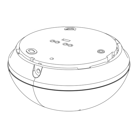
Device overview
Figure 1: Internal view
Table 1. Legend
Callout
Part
1
Pyro sensor
2
LED
3
Wiring terminal
Enrolling the device
Refer to the MX alarm panel instruction manual for
enrollment information.
Removing the bracket
Before wiring and mounting the device, rotate the
mounting bracket anticlockwise and pull it from the
detector. See Figure 2.
Figure 2: Removing the bracket
Installation guidelines
Consider the following guide when you choose a
suitable mounting location.
Figure 3: Device mounting hazards
1.
Keep away from heat sources.
2.
Do not expose to air drafts.
3.
Do not install outdoors.
4.
Avoid direct sunshine.
5.
Do not install near high voltage electrical lines.
6.
Do not install behind partitions.
7.
Do not mount on a moveable or unstable surface.
Notes:
Only qualified service persons can install the
l
device.
Do not partially or completely obscure the device's
l
field of view.
Do not install the MX-862 addressable ceiling
l
PIR detector in the following locations:
Hazardous areas.
l
Areas with a pollution degree higher than
l
pollution degree 2.
Circuits above overvoltage category II.
l
Install the MX-862 according to the Standard for
l
Installation and Classification of Residential Burglar
Alarm Systems, UL 1641.
Mounting and wiring the device
1.
Use the holes in the mounting bracket to mark and
drill three holes in the mounting surface. See Figure
4.
2.
Fasten the bracket to the mounting surface with
screws.
3.
Wire the device.
a.
Remove the jacket at the end of both cables to
expose the jacketed wires. To expose the
wires, remove the insulation at the end of each
wire. See Figure 5.
b.
Feed the wires through one of the pairs of
openings on the mounting bracket.
See Figure 6.
c.
For each cable, insert one wire in the positive
terminal loop that is marked L+ and the other
wire in the negative terminal loop that is
marked L-. See Figure 7.
d.
Screw both terminals closed with a flat-head
screwdriver. See Figure 8..
4.
Align the bracket tabs with the device slots and
rotate the device clockwise. Verify that it is
securely attached. See 1 and 2 in Figure 9.
5.
Fasten the device to the bracket with a screw. See
step 3 in Figure 9.
Figure 4: Marking, drilling and screwing the device
Figure 5: Removing
Figure 6: Inserting the
the cable and wire
cables through the cable
jackets
opening
Figure 7: Positive and negative terminal loops
Figure 8: Closing the terminal with a screwdriver
Figure 9: Attaching the device
Mounting height and detection distance
The following table outlines the detection distance in
relation to the mounting height:
Table 2. Mounting height and detection distance
2 m
3 m*
4 m*
Height
(6.6 ft)
(9.8 ft*)
(13.1 ft)
3.1 m
3.75 m
5 m
Detection distance radius
(10.2 ft)
(12.3 ft)
(16.4 ft)
Note:
UL/ULC verified detection only at 3.35 m (11 ft) radius
when the device is installed at 2.75 m (9 ft) height.
* For UL installations the maximum mounting height is
2.75 m (9 ft).
Walk testing
Perform a walk test of the coverage area at least once
a week to ensure that the device is working correctly.
1.
Set the alarm control panel to test mode to switch
the device to walk test mode.
2.
Walk test the coverage area by walking across the
far end of the coverage pattern in both directions.
The LED lights red each time it detects motion.
The device switches to normal mode when test mode
is disabled on the panel.
Note:
For detailed Placement instructions refer to the
l
control panel reference manual.
©2019 Johnson Controls. All rights reserved.
Tech. Support: 1-800- 387-3630
D-307587 Rev. 0 06/19
Device settings
To change a default device setting, select
DEVICE SETTINGS from the MX panel menu and
configure one or more setting options in the following
definition list:
Alarm LED: Select LED OFF to turn off the LED
l
indication of alarm events. LED ON is the default
setting
Walk test: Select Disable to disable the
l
LED indication of alarm events in walk test mode.
Enable is the default setting.
LED Event indication
The following table describes the LED patterns and the
corresponding events they indicate:
Table 3. LED event indications
LED
Event
Slow blinks
Walk test
Fast blinks
Enrollment mode
On for three seconds
Intruder detection
Specifications
General
Detector type: One pyroelectric sensor operating
l
in a dual separated configuration
Optical
Lens data: Fresnel type lens. Number of beams:
l
72.
Max. coverage: Ø10 m/360° at the maximum
l
installation height of 4 m (13.1 ft)
Figure 10: Beam distribution at 2.7 m (8.9 ft)
Side view
Top view
www.dsc.com
Advertisement

Related Manuals for Tyco MX-862


Summary of Contents for Tyco MX-862
- Page 1 Feed the wires through one of the pairs of Introduction LED Event indication openings on the mounting bracket. The MX-862 is an addressable smart ceiling PIR The following table describes the LED patterns and the See Figure 6. detector. It creates a 360° coverage area to detect the corresponding events they indicate: movement of intruders in indoor areas.
- Page 2 WARRANTY, BREACH OF CONTRACT, Side view The MX-862 is listed by UL 639 and by ULC- user license agreement is licensed to You under the marks of DSC or its suppliers. NEGLIGENCE, STRICT LIABILITY, OR ANY OTHER S306 for Intrusion-Detection Units terms of that license agreement.
Need help?
Do you have a question about the MX-862 and is the answer not in the manual?
Questions and answers