Advertisement
Quick Links
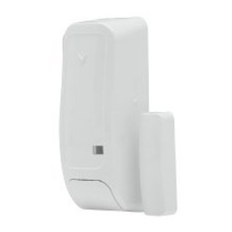
MX-975 Installation instructions
Addressable door and window cont act
Overview
MX- 975 is a hardwired magnetic door and window
contact device that is compatible with MX control
panels and is addressable in an MX-loop.
The detector has the following features:
Front cover tamper detection
l
Built-in reed switch that opens a circuit when the
l
magnet is moved from its normal position
Alarm and tamper LED indication
l
Figure 1: MX-975 detector parts
Table 1. Detector parts
Callout
Part
1
Screw cover
2
LED
3
Flexible retainer
4
Reed switch mark
5
Bracket
6
PCB support
7
Screw holes
8
Wiring inlets
Installation guidelines
The device enters a two-minute stabilization period
l
when it connects to the power supply for the first
time. Slow LED blinks indicate this event, but only if
the panel is in test mode.
Do not install the device in the following locations:
l
Hazardous locations
l
Areas with a pollution degree higher than
l
pollution degree 2
Circuits above overvoltage category II
l
Mounting guidelines
Mount the detector on the part of the frame that is
l
above the window or door and mount the magnet
below it on the window or door.
Do not mount the magnet more than 6 mm/0.25 in.
l
from the marked side of the detector. To find the
reed switch mark on the detector, see Reed switch
mark in Table 1.
Mounting and wiring the detector
1.
To remove the screw cover, insert a flat
screwdriver in the slot and use the screwdriver as
a lever. See Figure 2.
2.
To remove the detector cover, remove the screw
with a screwdriver and separate the cover from the
bracket. See Figure 3.
3.
To release the PCB, press the PCB support with
your finger or a screwdriver. See Figure 4.
4.
Hold the detector bracket in its final position on the
door or window frame. Mark and drill two holes
according to the mounting holes in the bracket.
Fasten the detector bracket to the mounting surface
with two countersunk screws. See Figure 5.
Note: Ensure the reed switch mark on the
detector faces the intended location of the magnet.
5.
Fasten the magnet in its final position with double-
sided adhesive tape or screws. See Figure 6.
Note: Before you fix the magnet in its final
position, align it according to the reed switch mark
on the detector. For more information, see Range
coverage directions.
6.
Fit the PCB into the PCB support.
7.
Wire the detector.
a.
Remove the jacket at the end of both cables to
expose the jacketed wires. To expose the
wires, remove the insulation at the end of each
wire. See Figure 7.
b.
Feed both cables through the cable openings.
See Figure 8.
c.
For each cable, insert one wire in the positive
terminal loop that is marked L+ and the other
wire in the negative terminal loop that is
marked L-. See Figure 9.
d.
Close both terminals with a flat-head
screwdriver. See Figure 10.
8.
Close the detector and magnet covers. Close the
detector cover with the screw and replace the
screw cover. See Figure 5. Slide the magnet cover
closed. See Figure 6.
Figure 2: Opening the screw cover
Figure 3: Opening the device cover
Figure 4: Removing the PCB
Figure 5: Marking, drilling, and screwing the detector
to a frame
Figure 6: Marking, drilling, and screwing the magnet
to a door or window
Figure 8: Inserting the
Figure 7: Removing
cables through the cable
the cable and wire
inlets
jackets
Figure 9: Positive and negative terminal loops
Figure 10: Screwing the terminal closed
Range coverage directions
When mounting the magnet, ensure that the distance
between the magnet and the reed switch mark on the
detector does not exceed the opening and closing
values in the following table.
For more information on the X, Y, and Z directions,
see Figure 11.
Table 2. Range coverage direction values
Non-metallic sur-
Supports
Metallic surface
face
Opening
Closing
Direction Opening
Closing
> 21 mm
< 19 mm
> 16 mm
< 15 mm
X
(0.87 in.)
(0.75 in.)
(0.35 in.)
(0.20 in.)
> 27 mm
< 24 mm
> 12 mm
< 10 mm
Y
(0.63 in.)
(0.55 in.)
(0.47 in.)
(0.40 in.)
> 13 mm
< 12 mm
> 12 mm
< 10 mm
Z
(1.06 in.)
(0.98 in.)
(0.71 in.)
(0.60 in.)
Note:
The values in Table 2 can vary by up to 10%.
l
For UL installations, the gap cannot be greater than
l
the measurements in Table 2.
For steel installations, the gaps cannot be smaller
l
than 3.175 mm.
©2019 Johnson Controls. All rights reserved.
Tech. Support: 1-800-387- 3630
D-307588 Rev. 0 06/19
Figure 11: Range coverage directions
Enrolling t he device
Refer to the panel installation manual to find the
enrollment procedure.
Disabling or enabling the alarm LED
indication
To enable or disable the LED indication, complete the
following steps:
1.
From the panel menu, select DEVICE SETTINGS.
2.
From the DEVICE SETTINGS menu, select Alarm
LED.
3.
Optional: Select LED OFF to disable the LED.
4.
Optional: Select LED ON to enable the LED.
5.
Exit the DEVICE SETTINGS menu.
LED ON is the default setting.
Compatible receivers
This device functions with MX panels and with
receivers that use MX technology.
LED event indications
Table 3. LED event indication
LED
Event
Fast blinks
Enrollment in progress
Intruder detection
On for 3 s
Specifications
General
Alarm input: One internal input
l
Tamper alert: Reports to the panel and the server
l
when a tamper event occurs
Elect rical
Communication protocol: MX
l
Power supply: MX bus 40 V
l
Current consumption: 0.2 mA average
l
quiescent, 3 mA maximum. Maximum current
consumption occurs during an alarm or when the
LED is on.
Environment al
Operating temperature: 0°C to 49°C or 32°F to
l
120.2°F
Relative humidity (RH): Average relative
l
humidity of approximately 75% non-condensing.
Note:
For 30 days per year, relative humidity may vary
l
between 85% and 95% non-condensing.
For UL installations, the relative humidity is 93%.
l
Physical
Dimensions (L x W x D): 81 x 34 x 25 mm or 3.2
l
in. x 1.34 in. x 1 in.
Weight (including battery): 53 g/1.9 oz
l
www.dsc.com
Advertisement

Related Manuals for Tyco Qolsys DSC MX-975


Summary of Contents for Tyco Qolsys DSC MX-975
- Page 1 Figure 4: Removing the PCB Figure 11: Range coverage directions Mounting and wiring the detector Figure 8: Inserting the Figure 7: Removing cables through the cable To remove the screw cover, insert a flat the cable and wire inlets screwdriver in the slot and use the screwdriver as jackets a lever.
- Page 2 You agree that You will not export or re- export the You acquire, You may have only one copy of the © 2018 Tyco International Ltd. and its Respective SOFTWARE PRODUCT to any country, person, or Limited Warranty SOFTWARE PRODUCT installed.
Need help?
Do you have a question about the Qolsys DSC MX-975 and is the answer not in the manual?
Questions and answers