Alber adventure A10 Service Manual
Hide thumbs
Also See for adventure A10:
- Operating instructions manual (71 pages) ,
- Technical documentation manual (48 pages) ,
- Technical documentation manual (48 pages)
Table of Contents
Advertisement
Quick Links
Adventure A10
Informationen für Therapeuten und Fachhändler
Adventure A10
Information for Therapists and DME Dealers
Adventure A10
Informations pour les thérapeutes et les
commerçants spécialisés
Adventure A10
Informazioni per i terapisti e rivenditori
3
Neu!
New!
Noveau!
Nuovo!
Auflage
Edition
Edition
Edizione
D
GB/US
F
I
Advertisement
Table of Contents

Related Manuals for Alber adventure A10


Summary of Contents for Alber adventure A10
- Page 1 Adventure A10 Informationen für Therapeuten und Fachhändler Adventure A10 GB/US Information for Therapists and DME Dealers Adventure A10 Informations pour les thérapeutes et les commerçants spécialisés Adventure A10 Informazioni per i terapisti e rivenditori Neu! Auflage New! Edition Noveau! Edition...
- Page 2 Adventure A10 Informationen für Therapeuten und Fachhhändler Adventure A10 GB/US Information for Therapists and DME Dealers Adventure A10 Informations pur les thérapeutes et les commerçants spécialisés Adventure A10 Informazioni per i terapisti e rivenditori...
-
Page 3: Table Of Contents
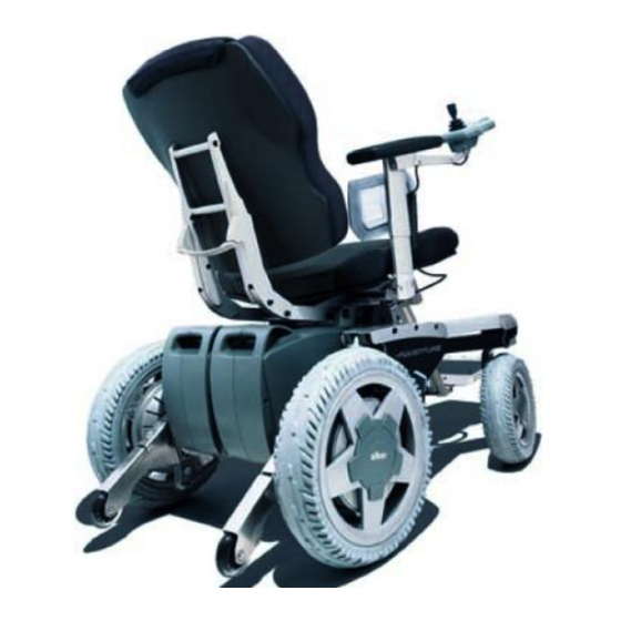
Contents Mechanical adjustments to the adventure Armrest height adjustment Armrest length adjustment Armrest sideways adjustment Backrest height adjustment only function seat (comfort and standard upholstery) Backrest angle of inclination adjustment Function seat Backrest angle of inclination adjustment Standard seat Seat length adjustment Function seat (standard and comfort upholstery) Leg support angle adjustment Function seat... - Page 4 Ordering information for spare parts can be found in our product manual. alber offers specialist dealers for medical accessories training courses for repairing the adventure and other alber products. Standard seat The adventure wheelchair is now equipped with the functio- nal or Recaro (optional) seating system and no longer with the standard seat.
-
Page 5: Mechanical Adjustments To The Adventure
1 Mechanical adjustments to the adventure 1.1 Armrest height adjustment – Loosen the two screws [1] located in the side support. – Push the armrest [2] to the desired height. – Tighten the two screws [1] again. 1.2 Armrest length adjustment –... - Page 6 – Pull the armrest [2] completely out of the holder [4]. – Loosen the two screws [6] located underneath the upholstery [5]. – Push the moveable part [7] to the desired position. – Tighten the two screws [6] again. – Push the armrest [2] back into the holder [4]. –...
-
Page 7: Armrest Sideways Adjustment
1.3 Armrest sideways adjustment – Tilt the entire seat [9] forwards. – Loosen the two screws [10] located under the seat. – Push the complete armrest [2] into the desired position. – Tighten the two screws [10] again. – Fold the seat carefully back down onto the chassis. Check the position of the armrest [2] in relation to the direction indicators. -
Page 8: Backrest Height Adjustment Only Function Seat (Comfort And Standard Upholstery)
1.4 Backrest height adjustment Only Function seat (comfort and standard upholstery) – Remove the cushion from the backrest. – Loosen and remove the 4 screws that hold the backrest to the support bracket [11]. – On the inside of the backrest there are 3 holes in each of two rows which are normally covered by the upholstery. -
Page 9: Backrest Angle Of Inclination Adjustment Function Seat
1.5 Backrest angle of inclination adjustment Function seat – Loosen the screws [13] in the support bracket. – Push the entire backrest [14] to the desired angle of inclination. – Tighten the screws [13] again. By adjusting the angle of inclination, the height of the backrest is also altered. -
Page 10: Backrest Angle Of Inclination Adjustment Standard Seat
1.6 Backrest angle of inclination adjustment Standard seat – Loosen and remove the four star grips [15]. – Pull or push the backrest [14] to the desired position. – Screw the four star grips [15] back in and tighten them. By adjusting the angle of inclination, the height of the backrest is also altered. -
Page 11: Seat Length Adjustment Function Seat (Standard And Comfort Upholstery)
1.7 Seat length adjustment Function seat (standard and comfort upholstery) – Pull the cushion off the seat. – Loosen and remove the four screws holding the seat. – On the inside of the seat there are 5 holes in each of two rows which are normally covered by the upholstery. -
Page 12: Leg Support Angle Adjustment Function Seat
1.8 Leg support angle adjustment Function seat – Remove the leg support from the seat. – Loosen the two screws [17] on the top of the leg support. The connecting piece [18] is now freely moveable. – Set the desired angle. –... -
Page 13: Leg Support Length Adjustment Standard And Function Seats
1.9 Leg support length adjustment Standard and function seats – Loosen the two screws [19] at the back of the leg support. – Pull or push the lower part of the leg support [20] into the desired position. – Firmly tighten the two screws [19] again. -
Page 14: Leg Support Footrest Angle Adjustment Function Seat
1.10 Leg support footrest angle adjustment Function seat – Loosen the screws [21] on both sides at the lower end of the leg support. – Push the retainer [22] into the desired position. – Check the retainer and with it the angle of the footrest. If necessary, the retainer [22] may have to be moved again. -
Page 15: Leg Support Footrest Length Adjustment Standard And Function Seats
1.11 Leg support footrest length adjustment Standard and function seats – Loosen the three screws [23] underneath the footrest. – The length can be adjusted by inserting the screws in one of the three sets of holes A, B or C. –... -
Page 16: Interface Instructions
1.12 Interface instructions The interface [25] located on the chassis is for the attachment of a peripheral module for the control of external drives. The cover [26] prevents the interface getting dirty or damaged and must only be removed if a device is to be attached. -
Page 17: Adjusting The Chassis Springing And Damping
Under some circumstances the springs will have to be exchanged or readjusted. This must only be undertaken by an authorised and trained dealer or by the alber Service Cen- ter (phone +49 (0) 800 90 96 250). The rear springs are principally responsible for the comfort of the ride and they can be finely set thanks to the adjustab-... -
Page 18: Adjusting The Rear Springing
* To carry out installation work and adjustments to the front part of the chassis, prior training by alber is a prerequisite. Please contact us for this. -
Page 19: Setting The Direction Indicators
1.14 Setting the direction indicators When the armrest is adjusted sideways (see chapter 1.3), it may prove necessary to re-position the two direction indicators [31]. – Loosen the two screws [32]. – Pull or push the direction indicator [31] into the desired position. -
Page 20: Setting The Seat Position Function Seat
1.15 Setting the seat position Function seat – Loosen the screws [34] on both sides of the holder stay [33]. – Pull or push on the holder stay [33] so that the entire seat holder moves into the desired position. –... -
Page 21: Setting The Seat Position Standard Seat
1.16 Setting the seat position Standard seat – Loosen and remove the screws [35] on both sides of the holder stay [33]. – Place the holder stay [33] against the hole positions desired. – Screw the holder stay [33] tight again using the screws [35]. -
Page 22: Fitting Mudguards (Optional Extra)
1.17 Fitting mudguards (optional extra) 1.17.1 Mudguards for the steering wheels – Thoroughly clean the connecting surface of the fork. It must be free of all dirt and grease. – Remove the self-adhesive foil [36] from the mudguard. – Push the mudguard [37] under the fork of the steering wheel. -
Page 23: Mudguards For The Powered Wheels
1.17.2 Mudguards for the powered wheels – Position the angle bracket of the mudguard [38] on the holder [39], as shown in the diagram. – Screw the mudguard [38] onto the holder [39]. 1.17.3 Fitting rear reflectors – Remove the adhesive foil [40] from the back of the rear reflectors [41]. -
Page 24: Control Unit Length Adjustment
1.18 Control unit length adjustment – Loosen the two screws [42] in the bracket [43] situated underneath the armrest. – Push the bracket holding the control unit to the desired position. – Tighten the two screws [42] again. -
Page 25: Settings On The Control Unit
2 Settings on the control unit 2.1 General information regarding programming mode In order to meet the different requirements of customers and the various sorts of disablement, the adventure provides a wide range of variable driving parameters. Programming can be carried out directly via the control unit without any additional device. -
Page 26: Changeable Parameters
2.3 Changeable parameters The following parameters may be adjusted to user require- ments directly via the control unit, without any external programming device: Select parameter set Indoor / Outdoor – The adventure allows the parameters for Indoor and Out- door use to be programmed independently of each other. For example, slow and fine for indoors and with maximum speed and precise straight ahead travel for outdoors (fac- tory setting). - Page 27 Turning speed – Determines the maximum speed at which an arc of a circle or curve is travelled at. – Reduction produces more stable straight forward driving at high speeds; at low speeds sluggish / tolerant. – Increase at lower speeds (indoors) improves travel round tight curves;...
- Page 28 Battery capacity – To provide most exact battery capacity indication, the battery size can be adjusted for 2 different types of the battery pack. – Factory pre-set according to battery size ordered. Change of direction joystick Particularly useful for users who can only displace the joystick in certain directions (e.g.
-
Page 29: Activating Service Mode
Speed reduction This parameter can only be altered in conjunction with the attachment of a periphery module. Chassis with short or long rocker – Setting 1 bar: More gentle braking (Setting only admissible for chassis with long wheelbase) – Setting 5 bars: Standard setting (without additional functions) Lighting/Direction indicators –... -
Page 30: Selection Of The Parameter Settings Indoor/Outdoor
2.5 Selection of the parameter settings Indoor / Outdoor Now you must choose the mode which you wish to change. Initially the mode in which you currently are will be shown. The following indicators apply: One bar display Outdoor mode Two bars display Indoor mode Outdoor Mode... -
Page 31: Changing The Parameters
2.6 Changing the parameters After you have established the mode which you wish to change, you can begin with the individual programming. By displacing the joystick to the left or right the various parameters described in chapter 2.3 may be set. The following apply: Displacement to the right: number code (1-15) is increased (change to the next highest parameter). -
Page 32: Reverting To Factory Parameters Settings
Displacement downwards: number of bars shown is decreased; the currently selected parameter is decreased or deactivated. Parameters, codes and possible settings can be found in the table in chapter 2.8 When programming is complete: – Pull the programming key [1] out of its location underneath the control unit. -
Page 33: Parameter Table
2.8 Parameter table 2.8.1 adventure version 6 km/h (Factory settings are marked in bold) Parameter Code Setting Nominal value Outdoor Driving program 1 bar 2 bars Indoor Parameter Code Display Indoor settings Outdoor settings indication Maximum 1 bar 1,3 km/h 1,3 km/h speed forwards 2 bars... -
Page 34: Adventure Version 10 Km/H
2.8.2 adventure version 10 km/h* * Not available in the USA (Factory settings are marked in bold) Parameter Code Setting Nominal value Outdoor Driving program 1 bar 2 bars Indoor Parameter Code Display Indoor settings Outdoor settings indication Maximum speed 1 bar 2,0 km/h 2,0 km/h... -
Page 35: Adventure Version 12 Km/H
2.8.3 adventure version 12 km/h (Factory settings are marked in bold) Parameter Code Setting Nominal value Outdoor Driving program 1 bar 2 bars Indoor Parameter Code Display Indoor settings Outdoor settings indication Maximum 1 bar 2,4 km/h 2,4 km/h speed forwards 2 bars 4,8 km/h 4,8 km/h... -
Page 36: Fault Detection / Fault Analysis Codes
2.9 Fault detection / fault analysis codes The adventure software is equipped with an automatic fault detection and analysis system. If a fault is detected in the system, it is shown on the LCD display of the control unit by means of a code number and symbol (see table below). - Page 37 Drive symbol flashes Uneven drive coding Left and right drive uneven. 6 km/h with Exclamation mark lit up 10 or 12 km/h or vice versa! Code 3 Fit identical drives on both sides Drive symbol flashes No communication with L4 has priority over R4! “left“...
- Page 38 - battery fuse (40A) defective - battery detection in Contact your specialist interface defective supplier or the alber Rapid error diagnosis Service Center if the by inserting the batte- error code continues to ries consecutively in the be displayed middle position! Control unit symbol flashes...
- Page 39 Drive symbol flashes „Left“drive hardware/ Drive must be checked system error at alber works Exclamation mark lit up Letter »L« flashes Code L0 Drive symbol flashes „Right“ drive hardware/ Drive must be checked system error at alber works Exclamation mark lit up Letter »R«...
- Page 40 12 km/h machine) or lit up wrong drive code! 1. Replace electronics Letter »L« flashes 2. Edit drive code (only possible in alber works) Code L5 Drive symbol flashes Wheel code/“Right“ Wrong electronics in electronic drive error drive (e.g. 6 km/h PCB...
- Page 41 Interface symbol flashes Hardware fault on Replace interface PCB interface or interface Exclamation mark lit up Letter »S« flashes Code S0 Interface symbol flashes CPU fault on interface Replace interface PCB or interface Exclamation mark lit up Letter »S« flashes Code S1 Interface symbol flashes RAM error on interface...
- Page 42 Complete seat unit* Hardware fault on Replace P-module PCD flashes peripheral module or P-module (different drive and/or Interface symbol flashes relay actuation) Exclamation mark lit up Letter »P« flashes Code P0 Complete seat unit* CPU fault on peripheral Replace P-module PCD flashes module or P-module...
- Page 43 Complete seat unit* Multiple occupancy of Programming error on flashes »decelerate« and/or P-module, replace »accelerate« indicator P-module Interface symbol key function flashes Exclamation mark flashes Letter »P« flashes Code P7 Complete seat unit* No counter-function to Programming error on flashes »left«...
- Page 44 Control unit ROM horizontal parity Clarify problem with symbol flashes error on special control manufacturer of fitted special control Interface symbol (replace special flashes control!) Exclamation mark lit up Letter »E« flashes Code E3 Control unit Joystick fault on special Clarify problem with symbol flashes control...
- Page 45 Brake symbol flashes Left and right brake Move brake lever to manually vented driving position! Battery capacity display (L= left brake only, R= Additional L or R dis- lit up right brake only) play indicates actuating pin jammed in wheel Exclamation mark lit up ejector or drive.
- Page 46 Ulrich Alber GmbH Vor dem Weißen Stein 21 Telefon (07432) 2006-0 72461 Albstadt-Tailfingen Telefax (07432) 2006-299 Germany www.alber.de...
Need help?
Do you have a question about the adventure A10 and is the answer not in the manual?
Questions and answers