Table of Contents
Advertisement
Quick Links
Programmable DC Power Supplies
Power System Series
GSPS30kW 0-600V / 0-3000A
GSPS45kW 0-600V / 0-4500A
GSPS60kW 0-600V / 0-6000A
Built in
Optional Interface: IEEE488.2 (GPIB), MODBUS TCP or EtherCAT
SAFETY & INSTALLATION MANUAL
Manual Supplements
The full user manual is available on TDK-Lambda website or can be ordered, refer to User manual IA761-04-02_.
For units equipped with MODBUS TCP interface option, refer to MODBUS TCP User manual IA761-04-04_.
For units equipped with EtherCAT interface option, refer to EtherCAT User manual IA761-04-05_.
Modbus® is a registered trademark of Schneider Electric, licensed to the Modbus Organization, Inc.
EtherCAT® is a registered trademark and patented technology, licensed by Beckhoff Automation GmbH,
Germany.
compliant LAN, USB, RS-232 & RS-485 Interface
Series
IA979-04-01A
Advertisement
Table of Contents

Related Manuals for TDK-Lambda Genesys GSPS10-3000


Summary of Contents for TDK-Lambda Genesys GSPS10-3000
- Page 1 SAFETY & INSTALLATION MANUAL Manual Supplements The full user manual is available on TDK-Lambda website or can be ordered, refer to User manual IA761-04-02_. For units equipped with MODBUS TCP interface option, refer to MODBUS TCP User manual IA761-04-04_. For units equipped with EtherCAT interface option, refer to EtherCAT User manual IA761-04-05_.
- Page 2 This page intentionally left blank...
- Page 3 This Manual Covers Models: 30kW: GSPS10-3000* GSPS100-300 GBSPS10-3000* GBSPS100-300 GSPS20-1500 GSPS150-204 GBSPS20-1500 GBSPS150-204 GSPS30-1020 GSPS200-150 GBSPS30-1020 GBSPS200-150 GSPS40-750 GSPS300-102 GBSPS40-750 GBSPS300-102 GSPS50-600 GSPS400-78 GBSPS50-600 GBSPS400-78 GSPS60-510 GSPS500-60 GBSPS60-510 GBSPS500-60 GSPS80-390 GSPS600-51 GBSPS80-390 GBSPS600-51 45kW: GSPS100-450 GBSPS100-450 GSPS20-2250 GSPS150-306 GBSPS20-2250 GBSPS150-306 GSPS30-1530 GSPS200-225 GBSPS30-1530...
-
Page 4: Table Of Contents
TABLE OF CONTENTS GENERAL INFORMATION ............................... 1 WARRANTY ................................... 1 ENVIRONMENTAL COMPLIANCE ............................ 1 INTENDED USE ................................2 LIFTING AND CARRYING ..............................2 NORMAL POSITION USE ..............................2 INSULATION REQUIREMENTS ............................2 LONG-TERM STORAGE METHOD AND LONG-TERM STORAGE PERIOD ................3 SAFETY &... - Page 5 CHAPTER 3: OUTLINE ..............................40 Power System Outline ......................40 CHAPTER 4: INSTALLATION ............................45 General ..........................45 Preparation for Use ......................45 Initial Inspection ........................45 GSPS Power System Packing Box Unpack ................46 Location, Mounting and Cooling ..................47 Installation...........................
- Page 6 This page intentionally left blank...
-
Page 7: General Information
This product must be returned to an authorized TDK-Lambda service facility for repairs or other warranty service. For products returned to TDK-Lambda for warranty service, the buyer shall prepay shipping charges to TDK- Lambda and TDK-Lambda shall pay the shipping charges to return the product to the buyer. Refer to section 4.11 for Repackaging for Shipment. -
Page 8: Intended Use
INTENDED USE This product is a professional equipment intended for use within industrial or laboratory environment, for generating DC output power within the limits of each model’s input and output specifications. It is NOT intended for home use or for use with children. This equipment is intended for use by a professional person, trained person, or informed person who received satisfactory training to be qualified to use this equipment. -
Page 9: Long-Term Storage Method And Long-Term Storage Period
LONG-TERM STORAGE METHOD AND LONG-TERM STORAGE PERIOD 1. Please keep the product in its packing box. 2. Please do not apply excessive vibration, shock or mechanical stress applied directly on the product. 3. Please keep away from direct sunlight. 4. For long-term storage temperature and humidity, the following conditions shall be used as a guideline: Temperature range: 5°C ~ 30°C. - Page 10 China ROHS 中华人民共和国中国电子行业标准 SJ/T11364-2014(中国RoHS2) People's Republic of China Electronic Industry Standard SJ/T 11364 -2014 (China RoHS2) Genesys+ Power System: 产品 / Product: GSPS 30kW, GSPS 45kW, GSPS 60Kw Series, GBSPS 30kW, GBSPS 45kW, GBSPS 60Kw Series. 有毒有害物质或元素 / Hazardous Substances 零件名称...
-
Page 11: Safety & Emc Approvals
Use of Certain Hazardous Substances in Electrical & Electronic Equipment regulation 2012. UKCA “Declaration of Conformity” in accordance with the preceding directives and standards has been made and is available on a file at our UK representative TDK-Lambda UK Limited, Kingsley Avenue, Ilfracombe, Devon EX34 8ES. -
Page 12: General Safety Information
Failure to comply with the safety precautions or warnings presented in this document violates safety standards of design, manufacture and intended use of this equipment and may impair the built-in protections within. TDK-Lambda shall not be liable for user’s failure to comply with these requirements. - Page 13 PRODUCT USAGE These products are designed for use as standalone equipment within the limits described in the safety and installation manual. They are not designed for general home or consumer use, and are designed for indoor use. ENVIRONMENTAL These products are IP20, and therefore chemicals/solvents, cleaning agents and other liquids must not be used.
- Page 14 IMPROPER USAGE OF THE EQUIPMENT If the equipment is used in a manner not specified by the manufacturer, the protection provided by the equipment may be impaired. USERS This equipment must be operated by qualified personnel only, who understand the instructions and safety manuals provided with the equipment.
-
Page 15: Informazioni Generali Di Sicurezza
La manutenzione di questi prodotti non può essere eseguita dal cliente. Le sostituzioni e le modifiche delle parti possono essere eseguite solo da personale di servizio autorizzato di TDK-Lambda. Per riparazioni e modifiche, il prodotto deve essere restituito alla struttura di manutenzione di TDK- Lambda. - Page 16 USO DEL PRODOTTO Questi prodotti sono progettati per essere usati come apparecchiatura autonoma nei limiti descritti nel manuale di sicurezza e di installazione. Non sono progettati per uso del consumatore o domestico generale, e sono progettati per uso in ambienti interni. AMBIENTALE Questi prodotti sono IP20, e di conseguenza non devono essere usati prodotti chimici/solventi, detergenti e altri liquidi.
- Page 17 INSTALLAZIONE L’installazione dell’apparecchiatura o del sistema che incorpora l’apparecchiatura deve essere eseguita in conformità con le istruzioni di installazione fornite dal produttore. La sicurezza di un sistema che incorpora l’apparecchiatura è responsabilità dell’assemblatore. USO IMPROPRIO DELL’APPARECCHIATURA Se l’apparecchiatura è usata in un modo non specificato dal produttore, la protezione fornita dall’apparecchiatura può...
-
Page 18: Información General De Seguridad
TDK-Lambda no se hace responsable por el incumplimiento de estos requisitos por parte del usuario. - Page 19 USO DEL PRODUCTO Estos productos están diseñados para usarse como equipo autónomo dentro de los límites descriptos en el manual de seguridad e instalación. No están diseñados para uso doméstico o de consumo general, y están diseñados para uso en interiores. MEDIOAMBIENTAL Estos productos son IP20 y, por lo tanto, no deben utilizarse productos químicos/solventes, agentes de limpieza y otros líquidos.
- Page 20 INSTALACIÓN La instalación del equipo o del sistema que incorpora el equipo debe realizarse de acuerdo con las instrucciones de instalación proporcionadas por el fabricante. La seguridad de cualquier sistema en el cual el equipo es incorporado es responsabilidad del ensamblador. USO INADECUADO DEL EQUIPO Si el equipo se utiliza de una manera no especificada por el fabricante, la protección proporcionada por el equipo puede verse afectada.
-
Page 21: Informations Générales De Sécurité
CA. ENTRETIEN Ces produits ne sont pas réparables par le client. Seul le personnel de service autorisé de TDK-Lambda peut procéder au remplacement ou au changement des pièces. Pour les réparations ou les changements, le produit doit être retourné au centre de service TDK-Lambda. - Page 22 UTILISATION DU PRODUIT Ces produits sont conçus pour être utilisés en tant qu'équipement autonome dans les limites décrites dans le manuel d'installation et de sécurité. Ils ne sont pas destinés à un usage domestique général ou à une consommation courante, et sont conçus pour une utilisation en intérieur. ENVIRONNEMENTAL Ces produits sont IP20, et par conséquent, les produits chimiques/solvants, les produits de nettoyage et autres liquides ne doivent pas être utilisés.
- Page 23 INSTALLATION L'installation de l'équipement ou du système intégrant l'équipement doit être conforme aux instructions d'installation fournies par le fabricant. La sécurité de tout système intégrant l'équipement est de la responsabilité du monteur. UTILISATION INAPPROPRIÉE DE L'ÉQUIPEMENT Une utilisation de l'équipement non conforme aux spécifications du fabricant comporte un risque d'altérer la protection fournie par l'équipement.
-
Page 24: Allgemeine Sicherheitshinweise
Reparatur dieses Geräts eingehalten werden. Die Nichteinhaltung der in diesem Dokument aufgeführten Sicherheitsvorkehrungen oder Warnhinweise verstößt gegen die Sicherheitsstandards bei der Konstruktion, Herstellung und dem bestimmungsgemäßen Gebrauch dieses Geräts und kann die eingebauten Schutzvorrichtungen beeinträchtigen. TDK-Lambda haftet nicht für die Nichteinhaltung dieser Anforderungen durch den Benutzer. SYMBOLE UND KENNZEICHNUNGEN AUF GERÄTEN Vorsicht, Risiko einer Gefahr. - Page 25 PRODUKTVERWENDUNG Diese Produkte sind für die Verwendung als eigenständige Geräte innerhalb der im Benutzerhandbuch beschriebenen Grenzen konzipiert. Sie sind nicht für den allgemeinen Heim- oder Verbrauchergebrauch und für die Verwendung in Innenräumen vorgesehen. UMWELT Diese Produkte entsprechen der Schutzart IP20, daher dürfen keine Chemikalien/Lösungsmittel, Reinigungsmittel und andere Flüssigkeiten verwendet werden.
- Page 26 EINBAU Der Einbau des Geräts oder der Anlage, in die das Gerät eingebaut ist, muss in Übereinstimmung mit den vom Hersteller bereitgestellten Installationsanweisungen erfolgen. Die Sicherheit eines Systems, das das Gerät enthält, liegt in der Verantwortung des Monteurs. NICHT BESTIMMUNGSGEMÄSSE VERWENDUNG DES GERÄTS Wenn das Gerät auf eine Weise verwendet wird, die nicht vom Hersteller angegeben ist, kann der vom Gerät gebotene Schutz beeinträchtigt werden.
-
Page 27: Informações Gerais De Segurança
O não cumprimento das instruções ou avisos de segurança apresentados neste documento viola os padrões de segurança, conceção, fabrico e a utilização pretendida deste equipamento, e poderá afetar as proteções nele incorporadas. A TDK-Lambda não poderá ser responsável pelo não cumprimento destes requisitos por parte do utilizador. - Page 28 UTILIZAÇÃO DOS PRODUTOS Estes produtos foram concebidos para utilização como equipamento autónomo, dentro dos limites descritos no manual do utilizador e para utilização em espaços interiores. Os produtos não foram concebidos para serem utilizados pelo consumidor em geral. AMBIENTAL Estes produtos são IP20 e, portanto, químicos/solventes, agentes de limpeza e outros líquidos, não deverão ser usados.
- Page 29 INSTALAÇÃO A instalação do equipamento ou do sistema que incorpora o equipamento deverá ser efetuada de acordo com as instruções de instalação fornecidas pelo fabricante. A segurança de qualquer sistema que incorpore o equipamento é da responsabilidade do profissional que procedeu à sua instalação. UTILIZAÇÃO IMPRÓPRIA DO EQUIPAMENTO Se o equipamento for utilizado de forma não especificada pelo fabricante, a proteção proporcionada pelo equipamento poderá...
-
Page 30: Product Safety Instructions
Failure to comply with the safety precautions or warnings in this document violates safety standards of design, manufacture and intended use of this equipment and may impair the built- in protections within. TDK-Lambda shall not be liable for user’s failure to comply with these requirements. - Page 31 PARTS SUBSTITUTIONS & MODIFICATIONS Parts substitutions and modifications are allowed by authorized TDK-Lambda Ltd. service personnel only. For repairs or modifications, the instrument must be returned to TDK-Lambda Ltd. service facility. AC INPUT Power System series is designed for use in TN and TT power distribution systems.
- Page 32 This page intentionally left blank...
-
Page 33: Chapter 1: General Information
CHAPTER 1: GENERAL INFORMATION 1.1 User Manual Content This safety & installation manual contains the operating instructions and installation instructions of the Power System series. The instructions refer to the standard & Blank Panel power supplies, including the built-in USB, LAN and RS232/485 serial communication. For information related to operation with the optional IEEE communication interface, refer to User manual, IEEE Option chapter. -
Page 34: Parallel Operation
1.2.4 Parallel Operation Power System series of the same output voltage and current rating can be paralleled in master-slave configuration with automatic current sharing to increase available power. Refer to User Manual (IA761-04-02_) for operation instructions. 1.2.5 Output Connections Output connections are made to output bus bars. Either the positive or negative terminal may be grounded or the output may be floated. -
Page 35: Optional Accessories
For ordering printed User Manual, the P/N is: G/M 1.3.2.2 Serial Port Cables For ordering serial port cables, refer to the User Manual. USB/LAN cables are not provided with the power system. 1.3.2.3 Paralleling Cable For ordering paralleling cables, please contact the TDK-Lambda sales. -
Page 36: Dust Filter Option
1.3.2.4 Dust Filter option: The Air Filter Kit is supplied separately from the power supply packing according to order. The usage of the air filter is according to customers’ needs. When using the air filter kit, all the specifications of the power supply remain the same as for standard power supply, with the exceptions specified in AIR FILTER KIT MANUAL –... - Page 37 AC Input Range AC Input Cable 190-240~, Three phase (222A) Min. 4 X 100mm . Three wires plus Safety ground, stranded copper, 300V, 105°C minimum, 3m max. length, outer diameter 48mm. 380-480~, Three phase (110.4A) Min. 4 X 35mm . Three wires plus Safety ground, stranded copper, 600V, 105°C minimum, 3m max.
-
Page 38: Chapter 2: Front/Rear Panel Controls And Connectors
Figure 2-1: Front Panel Controls and Indicators Control/Indicator Description Power Switch POWER ON/OFF control. Manufacturer logo TDK-Lambda logo. Voltage Encoder and Encoder: A high-resolution detent rotary Encoder adjusting the output Button voltage and navigating menu. Button: An auxiliary function to accept the voltage-setting value in Preview mode. - Page 39 Control/Indicator Description PROG Button / Indicator Activates the Program / Sequencer menu. The Program menu provides Sequencer function control, Trigger function control, and loads a sequence stored inside the power system memory. Green LED lights when Program menu is active. If Program menu is active, press PROG button to exit to the main display.
-
Page 40: Front Panel Display And Indicators
Control/Indicator Description PREV Button / Indicator Press the PREV button to display the Output Voltage and Current Limit settings. The display shows the settings for 5 seconds. If buttons are not pressed for 5 seconds, the display returns back to show actual output voltage and current. - Page 41 Control/Indicator Description Current Display 4-digit 16-segment Current display. Normally displays the output current. In preview mode, the display indicates the program setting of the output current. In menu navigation, the display indicates the selected parameter. LFP Indicator Locked Front Panel indicator. LFP is on if the Front Panel is locked.
-
Page 42: First Unit Blank Front Panel
Figure 2–3: Blank Front Panel Controls Connection Description Power Switch POWER ON/OFF control. Manufacturer logo TDK-Lambda logo. Power LED Power system ON/OFF status LED. Green LED lights when Power system is ON (Power Switch ON). REM LED REMOTE status LED. -
Page 43: First Unit Rear Panel Connections And Connectors
2.5 First Unit Rear Panel Connections and Connectors Refer to Figure 2- and Table 2- for description of the Rear Panel connectors. Figure 2-4: Rear Panel Connectors and Controls Connection Description AC Input Connector Not accessible for end-user. Ground Stud Functional Ground connection M4x15 Stud DC output Not accessible for end-user. -
Page 44: J1 Connector Terminal And Function
2.6 J1 Connector Terminal and Function Control and monitoring signals are SELV. Connector Technical Information: Connector type: 618026325223, WURTH DB26HD Receptacle type: 10090769-P264ALF, FCI Wire: AWG 24-28 Figure 2–3: J1 Connector Terminals and Functions Connection Description Daisy In / SO Input for Series Operation / Input for Shut Off control of the power supply output. - Page 45 Connection Description NOT USED NOT USED COMMON. Return for all signals. COMMON. Return for all signals. Enable / Disable the power supply output by dry-contact (short / open) or voltage source. Programmed Signal 2 General Purpose Open Drain Port 2. Programmed Signal 1 General Purpose Open Drain Port 1 Trigger In...
-
Page 46: Chapter 3: Outline
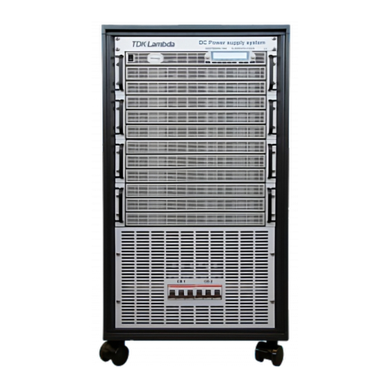
CHAPTER 3: OUTLINE 3.1 Power System Outline Power System Front View: MODEL NAME, OUTPUT RATING AND COMPANY LOGO... - Page 47 Power System Rear View: NOTE A locking key (2233x locking) that suitable for 2 side panels, is attached to rear panel grid with tie- wrap.
- Page 48 Power System Internal Rear Panel Connections: TABLE 1 BUSBAR VOLTAGE THICKNESS (T) 10V~20V 10mm 77mm 30V~40V 67mm 50V~100V 67mm 150V~600V 3.5mm 67mm...
- Page 49 Power System Optional Earth (Ground) Connection:...
- Page 50 Power System Side View and Output Bus-bars Dimensions: All Dimensions are in mm.
-
Page 51: Chapter 4: Installation
Keep all packing material until the inspection has been completed. If damage is detected, file a claim with carrier immediately and notify the TDK-Lambda sales or service facility nearest you. -
Page 52: Gsps Power System Packing Box Unpack
4.4 GSPS Power System Packing Box Unpack GSPS Power System considered as a very heavy unit. Follow unpack instructions carefully to avoid injury and/or GSPS unit damage. 1. Open the packing box as instructed in Figure 4-1 by remove the straps from the packaging box. 2. -
Page 53: Location, Mounting And Cooling
Figure 4-3: GSPS Unpack – Disassemble the side reinforcing beams 5. The Power System is ready to transport for placement Figure 4-4. Figure 4-4: GSPS Power System 4.5 Location, Mounting and Cooling This power system is fan cooled. The air intake is at the front panel and the exhaust is at the rear panel. -
Page 54: Installation
4.6 Installation 4.6.1 Preparing the Power System for AC Input and Output Connections 1. Unscrew fixing screw to remove the rear panel of the cabinet as shown in Figure 4-5. Figure 4-5: Rear Panel Disassembly 2. Unscrew the fixing screw to remove the rear panel slots of the cabinet as shown in Figure 4-6. Figure 4-6: Rear Panel Output Slots Disassembly... -
Page 55: Ac Input Power Connection
3. Disassemble the beam to allow easy access into the cabinet as shown in Figure 4-7. Figure 4-7: Rear Panel Disassembly 4.7 AC Input Power Connection This Power System has protective device (circuit breaker) which disconnect each current-carrying conductors with the following ratings: ... - Page 56 WARNING Some components inside the Power System are at AC voltage even when the On/Off switch is in the ”Off” position. To avoid electric shock hazard, disconnect the AC cord and load, and wait two minutes before removing cover. CAUTION AC Input Wires No Conductor Pretreatment: All kinds of copper conductors can be clamped without pretreatment (Solid, Flexible, with ferrule, with/without plastic sleeve).
- Page 57 1. Loose tightening nut on cable clamp in order to place AC cable through as shown in Figure 4-8. Figure 4-8: Loose Tightening Screw 2. Insert the AC wires into the AC input connector UKH as shown in Figure 4-9. 3.
-
Page 58: Turn-On Check Procedure
4.8 Turn-On Check Procedure WARNING There is a potential electrical shock hazard when using a power system without output protection. Do not turn ON power without output protection properly assembled. Turn OFF power system or disconnect power system from AC mains before making or changing any rear panel connection. WARNING The doors (on both the left and the right side) must be in LOCK position at all times to prevent access to hazardous parts and sections. -
Page 59: Constant Voltage Check (Blank Panel Master Power Supply)
4.8.4 Constant Voltage Check (Blank Panel Master Power Supply) 1. Connect a USB cable from a PC to J2 (USB interface connector). Refer to Table 2-4: Rear Panel Connectors and Controls. 2. Run terminal communication software and send the following commands to turn power system output INST:NSEL 6 OUTP 1 * Remember to use Carriage Return character (ASCII 13, 0x0D) after each command. - Page 60 5. Connect a USB cable from a PC to J2 (USB interface connector). Refer to Table 2-4: Rear Panel Connectors and Controls. 6. Turn the front panel Power switch to On position. 7. Run terminal communication software and send the following commands to turn power system output ON: INST:NSEL 6 OUTP 1...
-
Page 61: Connecting The Load
4.9 Connecting the Load 1. Turn off the AC input power before making or changing any rear panel connection. 2. Ensure that all connections are securely tightened before applying power. WARNING There is a potential shock hazard when using a power system with an output voltage greater than 60VDC. - Page 62 Output current Recommended wires Recommended Recommended lugs/Connector (mm²) wires (AWG/°C) 160A - 260A 4/0 = 0000/105°C 4/0 = 0000 For 30kW: 150V minimum Panduit LCMA95-8-L For 45kW: 200V Or equivalent For 60kW: 300V 260A - 500A 4/0 = 0000/105°C 4/0 = 0000 For 45kW: 150V minimum Panduit LCMA95-8-L...
-
Page 63: Wire Termination
WARNING There is a potential shock hazard if the Power System's rear cover are not assembled and fixed with screws. The AC input cover panel and output cover slots must be assembled during the AC mains and the system operation. 4.9.3 Wire Termination The wires should be properly terminated with terminals securely attached. - Page 64 For LV 10V ~ 100V Models: 1. Fix the wires to the Bus bars as shown in Figure 4-10 and Figure 4-11. Figure 4-10: Output Wires Assembly Figure 4-11: 10V-100V Wires Assembly NOTE All bus bars must be tightened by screw and nut, even if load wire (lug) is not connected. 2.
- Page 65 Figure 4-12: Assembly of Output Protection Slots WARNING The output bas burs are capable of providing hazardous energy, when using a power system with output voltage rated from 10VDC up to 100VDC. To protect personnel against accidental contact with the hazardous energy, ensure that the rear slot covers are installed on the output protection assembly in any case of operation, except if separately permitted in other sections in this manual.
- Page 66 For HV 150V ~ 600V Models: 1. Before first operation, ensure that the M6 screws that connect power supply output to bus-bars are not loss (general tightening Torque is 45~48 lbf.inch) – refer to Figure 4-13. Figure 4-13: power supply output screw connection 2.
-
Page 67: Grounding Outputs
NOTE All bus bars must be tightened by screw and nut, even if load wire (lug) are not connected. 3. Assembly the output protection slots as shown in Figure 4-16. Figure 4-16: Assembly of Output Protection Slots WARNING There is a potential shock hazard when using a power system with an output voltage greater than 60VDC. -
Page 68: Local And Remote Sensing
WARNING There is a potential shock hazard at the RS232/485, LAN, USB and the IEEE ports when using power supplies in series with combined voltage greater than 600V, and the Positive Output of the Power system is grounded. 4.10 Local and Remote Sensing The rear panel J8 sense connector may be used for remote sensing of the output voltage. - Page 69 Figure 4-17: Output Bus-bars Terminals Location Figure 4-18: Output Bus-bars Terminals Use remote sense where the load regulation at the load end is critical. In remote sense, the power system will compensate for voltage drop on the load wires. Refer to the specifications for the maximum allowable voltage drop on load wires. The voltage drop is subtracted from the total voltage available at the output.
-
Page 70: J8 Sense Connector Technical Information
4.11 Repackaging for Shipment To ensure safe transportation of the instrument, contact the TDK-Lambda sales or service facility near you for Return Authorization and shipping information. Please attach a tag to the power system describing the problem and specifying the owner, model... -
Page 71: Chapter 5: Specifications
CHAPTER 5: SPECIFICATIONS 5.1 60kW Series Specifications Unless otherwise noted, specifications are warranted over the ambient temperature range of 0° to 50° Celsius. 10-4500 20-3000 30-2040 40-1500 50-1200 60-1020 80-780 100-600 150-408 200-300 300-204 400-156 500-120 600-102 OUTPUT RATING 1.Rated output voltage (*1) 4500 (*3) 2.Rated output current (*2) 3000... - Page 72 FUNCTIONS AND FEATURES 1.Parallel operation Consult with manufacturer. 2.Constant power control Limits the output power to a programmed value. Programming via the communication ports or the front panel. Emulates series resistance. Resistance range: 1~1000mΩ. Programming via the communication ports or the front panel. 3.Output resistance control 4.Slew rate control Programmable Output rise and Output fall slew rate.
- Page 73 SAFETY/EMC 1.Safety standards IEC 61010-1:2010, IEC 61010-1:2010/AMD1:2016 Vout≤50V Models: 1.1.Interface classification Output, J1, J2, J3, J4, J5, J6, J7, J8 (sense) and J9 (communication options) are Non Hazardous. 60≤Vout≤600V Models: Output and J8 (sense) are Hazardous. J1, J2, J3, J4, J5, J6, J7 and J9 (communication options) are Non Hazardous. Vout≤50V Models: 1.2.Withstand voltage Input –...
-
Page 74: 45Kw Series Specifications
5.2 45kW Series Specifications Unless otherwise noted, specifications are warranted over the ambient temperature range of 0° to 50° Celsius. 20-2250 30-1530 40-1125 50-900 60-765 80-585 100-450 150-306 200-225 300-153 400-117 500-90 600-76.5 OUTPUT RATING 1.Rated output voltage (*1) 2.Rated output current (*2) 2250 1530 1125... - Page 75 FUNCTIONS AND FEATURES 1.Parallel operation Consult with manufacturer. 2.Constant power control Limits the output power to a programmed value. Programming via the communication ports or the front panel. Emulates series resistance. Resistance range: 1~1000mΩ. Programming via the communication ports or the front panel. 3.Output resistance control 4.Slew rate control Programmable Output rise and Output fall slew rate.
- Page 76 SAFETY/EMC 1.Safety standards IEC 61010-1:2010, IEC 61010-1:2010/AMD1:2016 Vout≤50V Models: 1.1.Interface classification Output, J1, J2, J3, J4, J5, J6, J7, J8 (sense) and J9 (communication options) are Non Hazardous. 60≤Vout≤600V Models: Output and J8 (sense) are Hazardous. J1, J2, J3, J4, J5, J6, J7 and J9 (communication options) are Non Hazardous. Vout≤50V Models: 1.2.Withstand voltage Input –...
-
Page 77: 30Kw Series Specifications
5.3 30kW Series Specifications Unless otherwise noted, specifications are warranted over the ambient temperature range of 0° to 50° Celsius. 10-3000 20-1500 30-1020 40-750 50-600 60-510 80-390 100-300 150-204 200-150 300-102 400-78 500-60 600-51 OUTPUT RATING 1.Rated output voltage (*1) 2.Rated output current (*2) 3000(*3) 1500... - Page 78 FUNCTIONS AND FEATURES 1.Parallel operation Consult with manufacturer. 2.Constant power control Limits the output power to a programmed value. Programming via the communication ports or the front panel. Emulates series resistance. Resistance range: 1~1000mΩ. Programming via the communication ports or the front panel. 3.Output resistance control 4.Slew rate control rogrammable Output rise and Output fall slew rate.
- Page 79 SAFETY/EMC 1.Safety standards IEC 61010-1:2010, IEC 61010-1:2010/AMD1:2016 Vout≤50V Models: 1.1.Interface classification Output, J1, J2, J3, J4, J5, J6, J7, J8 (sense) and J9 (communication options) are Non Hazardous. 60≤Vout≤600V Models: Output and J8 (sense) are Hazardous. J1, J2, J3, J4, J5, J6, J7 and J9 (communication options) are Non Hazardous. Vout≤50V Models: 1.2.Withstand voltage Input –...
Need help?
Do you have a question about the Genesys GSPS10-3000 and is the answer not in the manual?
Questions and answers