Table of Contents
Advertisement
Quick Links
Advertisement
Table of Contents

Related Manuals for HIKVISION iDS-2XM6810F-I/C


Summary of Contents for HIKVISION iDS-2XM6810F-I/C
- Page 1 Configuration & Installation Guidance of Mobile Dual-lens People Counting Camera...
-
Page 2: Table Of Contents
Contents Installation and Configuration Guide for Mobile Dual-lens People Counting Camera错 误 ! 未 定 义 书 签。 Chapter 1. Brief introduction ............................. 3 Chapter 2. Installation specification ......................... 4 Accessary..............................5 Required tools ............................6 Installation Position..........................6 2.3.1 General information .......................... 6 2.3.2 Bus Solution ............................ -
Page 3: Chapter 1. Brief Introduction
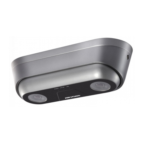
Chapter 1. Brief introduction iDS-2XM6810F-I(M)/C, mobile dual-lens people counting camera, based on the binocular stereo vision technology, adopting 3D head detection and 3D tracking, can obtain accurate real -time trajectory of all moving objects within the monitoring scope, analyze the trajectory data and achieve high-precision people counting. -
Page 4: Chapter 2. Installation Specification
Chapter 2. Installation specification For mobile cameras, installation and wiring are different from ordinary cameras. Please read this chapter carefully before installation and the below are some key points should be considered: Patch cord should be ordered in advance; ... -
Page 5: Accessary
2.1 Accessary Mobile dual-lens people counting camera Vibration-proof silicone pad Hexagonal screwdriver and screws (Include 4 expansion screws and self- tapping screws) Mounting Template Device patch cord, Ordered separately SAP code: 101505587,68 mobile dual-lens people counting camera coaxial,50cm, Hik White , customization... -
Page 6: Required Tools
1/2 of the Entry/Exit area. Keep the position in the center of Entry/Exit area. Lens of the camera should face downward vertically with logo of Hikvision inward. Keep the arrow on the sticker outward if the mounting template is used. -
Page 7: Bus Solution
Different installation height corresponds to different maximum detection widths. Please refer to the corresponding table of Lens Height - Maximum Detection Width when choosing the position, which avoids the situation that the passageway cannot be covered and detected completely after installation. The corresponding table of Lens Height - Maximum Detection Width is shown as below: Lens Height(m)... -
Page 8: Coach Solution
can cover the whole passageway, just install the camera above the door frame directly. If not, adjust the installation position inside, but the distance shouldn’t be more than 1/2 of the pedal area, otherwise it will affect the accuracy rate. Keep the lens downward and ensure the image in the Entry/Exit Area and near the door. -
Page 9: Installation And Wiring Step
Installation position for coach 2.4 Installation and Wiring Step 2.4.1 Installation Step Choose proper installation position and mount the camera according the following steps : Remove the housing by the hexagonal screwdriver: Thread cable through the hole and hold the pad to the camera’s base... -
Page 10: Wiring And Power On
Post the mounting template and keep it towards the outside of vehicle. Drill a hole on the vehicle for wiring, thread the camera’s cable through the hole and f ix the camera to the top of the vehicle with screws. Adjust the angle to make sure the lens is downward vertically and fix the lens. -
Page 11: Chapter 3 Configuration
3) Data transmission connection: It is different according to the host type (DVR or NVR). NVR Solution: Connect the network cable to the POE port of NVR. DVR: Connect the positive side of the power cable to the vehicle ignition switch, negative side to the GND and 485 cable to DVR. -
Page 12: 485 Configuration (It Is Needed Only When Dvr Is Used)
Pulse Signal: Enter [Configuration]-[Event]-[Basic Event]-[Alarm Input]. Set Alarm Input No as A<-1. If the alarm is triggered by high pulse, set “Alarm Type” as “NO”, if triggered by low pulse, set “Alarm Type” as “NC”. Then save the configuration. Set Alarm Input No as A<-2. -
Page 13: People Counting Configuration
3.1.4 People Counting Configuration Before the configuration, keep the door open. Enable People counting: [Configuration]-[People Counting], check “Enable People Counting”. Manual calibration mode: input the height (from Entry/Exit area to the camera) and click “Calibrate”, then a red frame and a yellow line will automatically appear in the image. The red frame is for counting and the yellow line is for detection. - Page 14 Draw the Entry/Exit area. Confirm the nodes which the supported maximum number is 10 by left mouse button and click right mouse button to confirm the drawn area. Save it after finishing the configuration. Set the Arming schedule and linkage method.
-
Page 15: Configuration Of Trigger Counting Mode
3.1.5 Configuration of Trigger Counting Mode: Enter [Configuration]-[People Counting]-[Data Uploading]. Choose the trigger counting mode according to the actual situation. a) None: It is enabled by default and not recommended. It will keep counting all the time and will influence the accuracy rate. RS-485 data transmission isn’t supported under this mode. -
Page 16: Related Parameters
3.1.6 Related Parameters HTTP Data Transmission: Our device supports transmit the people counting data via HTTP protocol.which is mainly used for the development of 3 party. OSD Overlay: It supports display the real-time counting information in the live view image. Enter, Leave, Enter/Leave and None are optional. - Page 17 Height Filter: Enable the function and set a height value. Persons and objects shorter than the set value are not counted as a valid target. Counting Status: It displays the current status of the camera. There are three types optional: Counting, Stop counting, Pause counting. You can click Refresh button to refresh the status.
-
Page 18: Configuration Instruction
Daily Reset Time: To reset the counter, you can set up a daily reset time. Or you can reset the counter manually by click Manual Reset. Clear Storage Data: To clear stored data on camera, you can click the Clear button. Always do the operation with caution. -
Page 19: Detection Line Configuration
3.2.2. Detection Line Configuration The detection line should be drawn inside the vehicle and near the boundary of door and ground. The length of detection line should cover the width of door properly. The position should be near the counting area, not too close to the edge of the counting area. -
Page 20: Chapter 4 Device Information Access
Chapter 4 Device Information Access Generally we need to get some related rules and configuration information during the debugging process. 4.1 Screenshot of Configuration Save the screenshot of Basic Information, Alarm input and Rule of people counting. 4.2 Internal Parameters Access Install the ClientDemo, open the ClientDemo and add the device. - Page 21 Click Product Related—BV Correct.
-
Page 22: Get Dual-Lens Video
4.3 Get Dual-lens Video Access the camera via web browser. Enter [Configuration]-[Video & Audio]-[Video]. Set stream type as Sub Stream and modify the Max Bitrate to 8012Kbps, then save it. - Page 23 Switch the stream type to Sub Stream in the live view interface (The image will be displayed as a montage image which includes the upper and lower image). Click Start Recording button to record, then save it.
Need help?
Do you have a question about the iDS-2XM6810F-I/C and is the answer not in the manual?
Questions and answers