Table of Contents
Advertisement
Quick Links
Operating manual
Betriebsanleitung .................................................... Seite 1 - 34
Operating manual .................................................. page 35 - 68
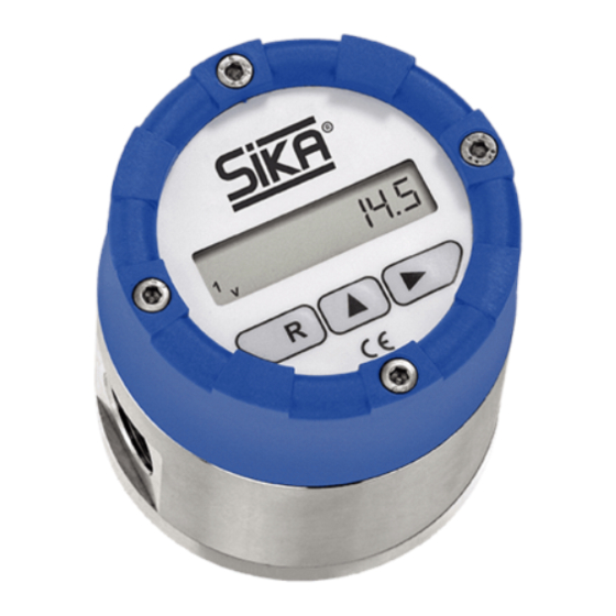
Oval gear flow meters VO
Types VO...VA, VO...VP, VO...AP
Sizes 015, 06, 1, 2, 5, 10, 50, 115
Please keep this operating manual for future reference.
If the appliance is resold, please provide the operating manual along with it.
(Translation)
Advertisement
Table of Contents

Related Manuals for SIKA VO VA Series


Summary of Contents for SIKA VO VA Series
- Page 1 Operating manual (Translation) Betriebsanleitung ............ Seite 1 - 34 Operating manual ..........page 35 - 68 Oval gear flow meters VO Types VO…VA, VO…VP, VO…AP Sizes 015, 06, 1, 2, 5, 10, 50, 115 Please keep this operating manual for future reference. If the appliance is resold, please provide the operating manual along with it.
-
Page 2: Table Of Contents
Offenders will be held liable for the payment of damages. All rights reserved in the event of the grant of a patent, utility model or design. - 36 - © SIKA • Ba_VO • 06/2015... -
Page 3: About This Operating Manual
Dr. Siebert & Kühn GmbH & Co. KG Struthweg 7-9 • D - 34260 Kaufungen 05605-803 0 • 05605-803 54 info@sika.net • www.sika.net Hazard signs and other symbols used: CAUTION! Electric current! This sign indicates dangers which could arise from handling of electric current. -
Page 4: Device Description
In addition, the VO can also be combined with a sensor or high temperature "sen- sor". Further information on the material combinations, size, display units and sensors can be found in our catalogues at "catalogues.sika.net" - 38 - © SIKA • Ba_VO • 06/2015... - Page 5 Device description Type plates: The type plates are located on the measuring chamber housing or on the housing of display de- vice. It contains the most important data ( Example). Examples type plates Scope of delivery and accessories: Check the delivered items and ordered accessories for completeness. Compare the device data with the data on the delivery note and in the order records.
-
Page 6: Intended Use
We accept no liability for any damage or malfunctions resulting from incorrect installation, in-appropriate use of the device or failure to follow the instructions in this operating manual. - 40 - © SIKA • Ba_VO • 06/2015... -
Page 7: Safety Instructions
In order to guarantee that the device operates safely, the operator must act competently and be conscious of safety issues. SIKA provides support for the use of its products either personally or via relevant literature. The customer verifies that our product is fit for purpose based on our technical information. -
Page 8: Construction And Function
The number of revolu- tions is directly proportional to the flow rate. The output signal of the sensor is evaluated by the electronics and shown in the display. - 42 - © SIKA • Ba_VO • 06/2015... -
Page 9: Installation And Operating Of The Measuring Chamber Housing
Installation and operating of the measuring chamber housing Installation and operating of the measuring chamber housing Before installing the device, check that the pressure bearing parts have not been damaged during transportation the wetted materials of the device are suitable for the media being used ( § 10.1 "Wetted parts' materials"). -
Page 10: Mounting
Install the oval gear flow meter in the pipeline free from strain. Installation position: Correct! Wrong! Horizontal pipe work: Vertical pipe work: - 44 - © SIKA • Ba_VO • 06/2015... -
Page 11: Sensor And Display Unit
Sensor and display unit Sensor and display unit Sensor: For connection to evaluation electronics or a PLC of the user there's a separate sensor with M12x1 thread in stock. In addition to the standard sensor there is a high temperature sensor for the types VO…VA available. -
Page 12: Electrical Connection
The display units 2 and 3 contain two cable bushings for one external sensor and/or pulse output. The terminal compartment has up to two reed sensors that can be connected via plug-in connectors. The electronics can be combined with any meter that uses reed sensors. - 46 - © SIKA • Ba_VO • 06/2015... - Page 13 Sensor and display unit External Sensor (only displays 2+3): The external reed sensor can transmit pulses to either pulse input A or B depending on the measuring task and the operating mode. A sliding switch AB is provided on the connec- tion circuit board for this purpose.
-
Page 14: Replacing The Battery (Displays 1 And 2)
Exploded drawing of display unit 2 Make sure the display is positioned correctly (check via the film at the front) before in- stalling the 4 crosshead screws Incorrect installation may damage the display! - 48 - © SIKA • Ba_VO • 06/2015... -
Page 15: Operation And Handling
Operation and handling Operation and handling CAUTION! Material damage! Erratic or rapid flow increase when starting up the VO may cause damage to the oval wheels, bearings and seals. Start up the oval gear flow meter with slowly increasing flow. Before switching on for the first time, check that ... -
Page 16: Key Functions In Normal Mode
V1 or V2 meter has returned to “0”. The quantity is lost! “E” appears on the display during the return process. The message “E” is saved and can be deleted by pressing the "" key. Select operating mode “1” - 50 - © SIKA • Ba_VO • 06/2015... - Page 17 Operation and handling 6.3.2.2 Total volume measurement “A” + “B” is calculated as the total volume measurement for the volume / mass measure- ment. There is no return identification. Separate K factors are applied. The total of “A+B” is displayed at all meters. K factor A and B can be set separately. Select operating mode “2”.
- Page 18 (optional). The current measured temperature is displayed in 0.5°steps in level 14. The medi- um temperature can be used to calculate the density. If a temperature sensor is not used, a temperature of 20 °C is always displayed. - 52 - © SIKA • Ba_VO • 06/2015...
- Page 19 Operation and handling 6.3.9 Pulse outputs (level 24 and 25) (only displays 2 and 3) 6.3.9.1 Original pulses Irrespective of the operating mode, only the pulses which reach pulse input “A” are output as original pulses. The pulse duration for original pulses is always 4 ms and cannot be altered. 6.3.9.2 Scaled pulses Depending on the volume/quantity of mass, pulses can be output at the pulse output.
- Page 20 After accessing the programming level, change “0” to “1” in channel 36 in order to reset the main meter. The meter (V1) is reset to 0 after exiting the programming menu. - 54 - © SIKA • Ba_VO • 06/2015...
- Page 21 Operation and handling 6.3.13 Current output (level 123 and 124) (only display 3) The measured flow rate in the “Q” display can be output as current at the 4-20 mA current output. The flow rate value for the lower measuring range limit (4 mA) and the flow rate value for the upper measuring range limit (20 mA) are displayed in level 123 and 124 respectively.
-
Page 22: Open Collector Pulse Output (Displays 2 And 3)
8 to a resistance of approx. 10 kΩ for voltages of between 5 and max. 24 V. The cur- rent carrying capacity of the output is max. 30 mA. If a voltage is applied to terminal 8 without resistance, the output stage of the electronics will be destroyed. - 56 - © SIKA • Ba_VO • 06/2015... -
Page 23: Level And Parameter Operating Menu
Operation and handling 6.5 Level and parameter operating menu Display 1: Level Parameter Note Operating mode 1: A and B at a measuring chamber, possibility of return identification. Volume unit Selection of the volume unit. When "mass" unit, then calculation of the density Time unit Conversion of the flow rate into the selected time unit. - Page 24 4 Current simulation 0.00: Off, all other values between 4.00 and 20.00 result in a simulated current output. Password Password can be entered and changed for programming protection. 0000 = off - 58 - © SIKA • Ba_VO • 06/2015...
-
Page 25: Problems
Problems Problems CAUTION! Material damage! The VO cannot be repaired by the user! In case of a defect, the device must be returned to the manufacturer for repair. Never open the VO and perform any repair yourself. If a fault occurs or there is suspicion of an incorrect measurement, check the installation in- structions and mounting (... -
Page 26: Repair, Hazardous Media
The VO consists of various different materials. It must not be disposed of with household waste. Take the VO to your local recycling plant send the VO back to your supplier or to SIKA. - 60 - © SIKA • Ba_VO • 06/2015... -
Page 27: Technical Data
Technical data 10 Technical data The technical data of customised versions may differ from the data in these instructions. Please observe the information specified on the type plate. 10.1 Characteristics VO VO…VP * VO…AP * Type VO…VA Characteristics Measuring range [l/min] 0.03…660 •... - Page 28 Degree of protection (EN 60529) * *1 High temperature sensor (only with VO…VA). *2 High temperature sensor only PNP. *3 with plug or when correctly installed on the measuring chamber housing or wall mounting unit. - 62 - © SIKA • Ba_VO • 06/2015...
-
Page 29: Dimensions
Technical data 10.2 Dimensions Process connection female thread: Without a display Display 1 Display 2 / Display 3 Size VO 015 VO 06 VO 1 VO 2 VO 5 VO 10 VO 50 VO 115 A [mm] C [mm] *, D [mm] Installation size [mm] G¼... - Page 30 Technical data Wall mounting plate: - 64 - © SIKA • Ba_VO • 06/2015...
-
Page 31: Pressure Drop
Technical data 10.3 Pressure drop Technical changes reserved - 65 -... - Page 32 Technical data - 66 - © SIKA • Ba_VO • 06/2015...
- Page 33 For your notes Technical changes reserved - 67 -...
- Page 34 Mess- und Sensortechnik Sensors and Measuring Instruments Durchflussmesstechnik Flow Measuring Instruments Test- und Kalibriertechnik Test and Calibration Instruments SIKA Dr. Siebert & Kühn GmbH & Co. KG Struthweg 7–9 D-34260 Kaufungen Germany +49 (0)5605 803-0 +49 (0)5605 803-54 info@sika.net...
Need help?
Do you have a question about the VO VA Series and is the answer not in the manual?
Questions and answers