Table of Contents
Advertisement
Quick Links
Advertisement
Table of Contents

Related Manuals for ITT Goulds Pumps HS


Summary of Contents for ITT Goulds Pumps HS
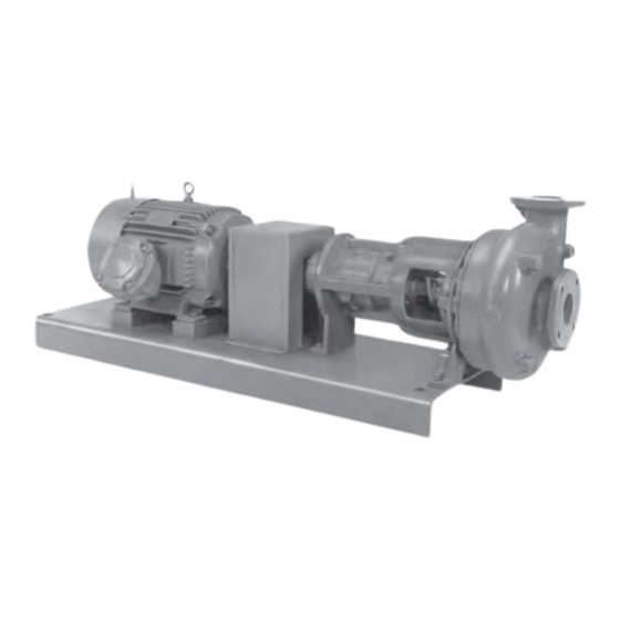
- Page 1 Installation, Operation, and Maintenance Manual Model HS...
-
Page 3: Table Of Contents
Table of Contents Table of Contents 1 Introduction and Safety ............................ 2 1.1 Important Safety Notice..........................2 1.2 Safety Warnings ............................2 1.3 Safety ................................ 3 1.4 General precautions ..........................3 1.5 Parts ................................6 2 General Information ............................7 2.1 Preparation for shipment ........................... -
Page 4: Introduction And Safety
ITT Goulds pumps will provide safe, trouble-free service when properly installed, maintained, and operat- Safe installation, operation, and maintenance of ITT Goulds Pumps equipment are an essential end user responsibility. This Pump Safety Manual identifies specific safety risks that must be considered at all times during product life. -
Page 5: Safety
Trapped liquid can rapidly expand and result in a violent explosion and injury. ITT Goulds Pumps will not accept responsibility for physical injury, damage, or delays caused by a failure to observe the instructions for installation, operation, and maintenance contained in this Pump Safety Manual or the current IOM available at http://www.gouldspumps.com/literature. - Page 6 WARNING NEVER operate pump with discharge valve closed. WARNING NEVER operate pump with suction valve closed. WARNING DO NOT change service application without approval of an authorized ITT Goulds Pumps representative. WARNING Safety Apparel: • Insulated work gloves when handling hot bearings or using bearing heater •...
- Page 7 1.4 General precautions When installing in a potentially explosive environment, please ensure that the motor is properly certified. WARNING Operating pump in reverse rotation may result in contact of metal parts, heat generation, and breach of containment. WARNING Lock out driver power to prevent accidental start-up and physical injury. WARNING The impeller clearance setting procedure must be followed.
-
Page 8: Parts
1.5 Parts The use of genuine Goulds parts will provide the safest and most reliable operation of your pump. ITT Goulds Pumps ISO certifica- tion and quality control procedures ensure the parts are manufac- tured to the highest quality and safety levels. -
Page 9: General Information
2 General Information 2 General Information 2.1 Preparation for shipment Goulds pumps are prepared at the factory for shipment under covered conditions. They are protected for transport and short term covered storage. Unless otherwise specified, it is assumed the pump will be in- stalled upon delivery. - Page 10 2.2 Installation Figure 1: Typical anchor bolt Installing Pump on Foundation If sub-bases or floor-plates were directly anchored to poured concrete foundations, surface irregularities would cause distortion. Rectangular metal blocks and shims, or metal wedges having a small taper, are placed beside each anchor bolt to level the sub-base or floor-plate, see Figures below, Leveling with Wedges and Leveling with Blocks and Shims.
-
Page 11: Pump Driver Alignment
2.3 Pump Driver Alignment Figure 3: Leveling with blocks and shims When the grout has hardened and the anchor bolts are permanently secured, recheck level. NOTICE: On large subbase/floorplates, shimming is recommended to be at 24" spacing. Figure 4: Typical 2.3 Pump Driver Alignment Shaft alignment of horizontal pump and driver Pumps and drivers that are received from the factory with both machines mounted on a common sub-... - Page 12 2.3 Pump Driver Alignment “Alternate Method” of alignment described in the Pump/Driver Alignment section, is recommend- Sub-base mounted horizontal pumps may be shipped with or without drivers and gears. Be sure pump and drivers are uncoupled before installation. Level by shimming beside each anchor bolt and grout.
- Page 13 2.3 Pump Driver Alignment Figure 7: Checking Parallel Alignment NOTICE: Care must be taken to have the straight edge parallel to the axis of the shafts (Figure Checking Parallel Alignment). Angular and parallel misalignment are corrected by means of shims under the motor mounting feet. After each change, it is necessary to recheck the alignment of the coupling halves.
-
Page 14: Stuffing Boxes
2.4 Stuffing Boxes Alignment of gear type couplings Gear type couplings are aligned in the same manner as outlined above. However, the coupling covers must be moved back out of the way and measurements made on the coupling hubs as shown in Figure Gear Coupling Alignment. - Page 15 2.4 Stuffing Boxes Packing Original equipment packing is a suitable grade for the service intended. To replace original packing, con- tact local packing suppliers. Figure 9: Typical Stuffing Box Refer to 2.9 Bill of Material and Assembly Drawing on page 16 for specific packing size and configura- tion.
-
Page 16: Pump Start-Up
2.5 Pump Start-up A significant amount of lubricating liquid should leak from gland side of stuffing box. Operate pump for at least 15 minutes before tightening gland nuts. Make small, even gland nut adjust- ments to reduce leakage. Allow adequate run-in time between adjustments. Acceptable leakage is 30-50 drops per minute. -
Page 17: Water Hammer
2.6 Water Hammer Lubricating Lines to Stuffing Box Lubricating liquid must be flowing to the stuffing box before the pump is started. Both mechanical seals and packing require lubrication for continuous service. Priming The pump must be completely primed before operation. 2.6 Water Hammer Water hammer is a high pressure surge within a closed pipe system, created by rapid change in the flow rate. -
Page 18: Bill Of Material And Assembly Drawing
2.9 Bill of Material and Assembly Drawing 2.9 Bill of Material and Assembly Drawing Model HS Installation, Operation, and Maintenance Manual... -
Page 19: Bearing Frame Assembly
3 Bearing Frame Assembly 3 Bearing Frame Assembly 3.1 General The inboard of lower bearing is an angular contact ball bearing with high thrust capacity and the out- board or top bearing is a high radial capacity ball bearing. Grease is the standard lubricant, but bearing assemblies can be furnished for oil lubrication. -
Page 20: Installing A Bearing
3.3 Installing a bearing Figure 11: Oil Lubrication NOTICE: "N" - with thrust bearing, (112C), tight against inboard end cover (119B), measure length "L" and install necessary shims to make .005" - .008" gap at "G". 3.3 Installing a bearing Long bearing life is quite dependent on careful handling of the bearing when it is out of the housing and during the installation procedure. -
Page 21: Assemble The Bearing Assembly
3.6 Assemble the bearing assembly 3.6 Assemble the bearing assembly Figure 12: Model HS Bearing Assembly NOTICE: "N" - with thrust assembly bearing (112C) tight against retainer (119B) measure "L" and install necessary shims to make .005 to .008 gap at "G". Press the bearings on the shaft. -
Page 22: Liquid End
4 Liquid End 4 Liquid End 4.1 General Instructions The impeller of the HS pump is recessed in a circular opening at the back of the casing. The uniform running clearance between the impeller and the casing keeps a uniform pressure around the outside of the impeller, and the resulting hydraulic forces on the impeller are low compared to the conventional cen- trifugal pump. -
Page 23: Assemble The Liquid End
4.4 Assemble the Liquid End The standard impeller has an impeller nut and drive key. Unscrew the impeller nut (right hand pump will have a right hand impeller nut) and then carefully pull the impeller off the end of the shaft. Remove the cap screws which fasten the stuffing box cover (184) to the bearing housing (134A). - Page 24 Visit our website for the latest version of this document and more information: http://www.gouldspumps.com Goulds Pumps Inc. 240 Fall Street Seneca Falls, NY 13148 Form IOM.HS.en-US.2022-03 ©2022 ITT Corporation The original instruction is in English. All non-English instructions are translations of the original instruction.
Need help?
Do you have a question about the Goulds Pumps HS and is the answer not in the manual?
Questions and answers