Table of Contents
Advertisement
Quick Links
OPERATION MANUAL / SPARE PARTS LIST
PNEUMATIC STEEL
STRAPPING TOOL
MODEL A383.0003
13.6746.01
CE Declaration of conformity
We declare that the machine A383
is in conformity with the following standard or
standardised documents:
98/37/EEC
FROMM Holding AG
Hinterbergstrasse 26
CH - 6330 Cham
03.04.2002
R.Fromm
Director
For Parts & Service 1-877-862-6699
Advertisement
Table of Contents

Related Manuals for Fromm A383.0003


Summary of Contents for Fromm A383.0003
- Page 1 OPERATION MANUAL / SPARE PARTS LIST PNEUMATIC STEEL STRAPPING TOOL MODEL A383.0003 13.6746.01 CE Declaration of conformity We declare that the machine A383 is in conformity with the following standard or standardised documents: 98/37/EEC FROMM Holding AG Hinterbergstrasse 26 CH - 6330 Cham 03.04.2002...
-
Page 2: Table Of Contents
INDEX PAGE SAFETY INSTRUCTIONS WARRANTY CONDITIONS AND LIABILITY APPROPRIATE USE CHART OF TYPES TECNICAL DATA INSTALLATION OPERATING CONTROLS OPERATION Feeding the strap around the package ....... 7 Loading the strap. -
Page 3: Safety Instructions
SAFETY INSTRUCTIONS Read these instructions carefully. Failure to follow these instructions can result in severe personal injury. Eye injury hazard Strap breakage hazard Failure to wear safety glasses with side shields can result in Improper operation of the tool, excessive tensioning, using strap severe eye injury or blindness. -
Page 4: Warranty Conditions And Liability
WARRANTY CONDITIONS AND LIABILITY FROMM Holding AG warrants all its strapping tools and machine heads during a period of 24 months from the date of installation at the end-user's sight by the distributor, however, not later than 30 months from the date of shipment to the distributor of FROMM Holding AG. -
Page 5: Tecnical Data
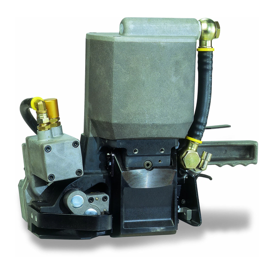
TECNICAL DATA Description of the tool The tool model A383 has been designed to strap packages with steel strapping. The steel strapping is fed around the package manually or in combination with a strap feeder. The strap is inserted in the tool, tensioned, sealed by punching and at the same time the strapping is cut from the strap coil. - Page 6 Compressed air Joining thread: G1/4 Max. air pressure: 6 bar / 87 psi. Air flow of air unit: min. 850 Nl/min / 30 cu.ft /min with a maximum pressure drop of 0.5 bar / 7.25 psi. Air consumption Tensioning: approx. 12 Nl / 0.43 cu.ft uncompressed air per second with the air motor running. Sealing: approx.
-
Page 7: Operating Controls
OPERATING CONTROLS Lever Catch Motor valve lever Sealing valve lever Flapper valve lever OPERATION When handling strap, always wear protective gloves and safety glasses with side shields which conform to ANSI Standard Z87.1. Feeding the strap around the package The strap is fed around the package in the direction as shown in the illustration. -
Page 8: Tensioning The Strap
Tensioning the strap The motor valve lever is pressed down with the thumb of the right hand so that the catch locks. Let the tool tension until the motor stalls. If the tensioning cycle has to be interrupted (faulty strapping, applying of corner protection angles) press the red lever. -
Page 9: Seal Control
SEAL CONTROL A regular control of the seal is necessary. The seal can be checked visually and the person controlling can easily judge the quality of the seal. When checking the seal the following illustrations must be compared. Correct seal A correct seal must be conform to the illustration. -
Page 10: Seal Adjustment
10 SEAL ADJUSTMENT The depth of the sealing mechanism and the cutter can be steplessly adjusted by turning the adjusting screw with a screw driver. Sealing depth is excessive Turn adjusting screw clockwise. ° A turn of 90 equals a stroke correction of 0.25 mm/.010". -
Page 11: Maintenance
11 MAINTENANCE Depending on the working conditions and the use of the tool the following maintenance has to be made periodically: 11.1 Air-unit • Checking the air pressure daily. • Checking the oil-level daily. • The water separator must be emptied before it is full (unless automatic). •... -
Page 12: Cleaning
11.3 Cleaning If impact of dirt and dust is considerable and if painted straps are used the feed wheel must be cleaned regularly. Normally it is sufficient to blow out this part by using an air gun. 11.4 Lubrication The gear is filled with MOLYKOTE BR 2 PLUS. Use the same type of grease after repairs. When being exchanged, all valve parts and other movable parts have to be greased with grease of type Mobilux EP2 or with any equivalent product. -
Page 13: Exchange Of The Feed Wheel
12.2 Exchange of the feed wheel • Remove the left strap stop • Unscrew the three screws and remove the bearing cover. • Remove the front distance ring, the O-ring and the feed wheel from the feed wheel shaft. • Assembling in opposite order. Important! Take notice of the assembling position of the feed wheel. -
Page 14: Exchange Of Cutter
12.4 Exchange of cutter • Remove base plate, guard plate with guide and right strap stop. • Using a hexagon socket spinner wrench to unscrew and remove cutter screw M6 x 12 across the appropriate boring in the sealing body. •... -
Page 15: Control System
13 CONTROL SYSTEM 13.1 Pneumatic schematic PNS.1007 POS. DESCRIPTION Throttle 1,2 Throttle 1,2 Flapper valve Flapper security valve Sealing valve Motor valve Throttle valve Pilot valve Throttle Throttle 1,8 Holding air throttle 2,0 Non-return valve Diaphragm Holding air valve Air-pressure-reduction-valve Throttle 1,2 Rocker cylinder Throttle 1,2... -
Page 16: Details Of The Control System
13.2 Details of the control system POS. DESCRIPTION Throttle 1,2 Throttle 1,2 Flapper valve Flapper security valve Sealing valve Motor valve Throttle valve Pilot valve Throttle Throttle 1,8 Holding air throttle 2,0 Non-return valve Diaphragm Holding air valve Air-pressure-reduction- valve Throttle 1,2 Rocker cylinder Throttle 1,2... -
Page 17: Functional Characteristics
14 FUNCTIONAL CHARACTERISTICS Idle position Because of the connection of the tool to the compressed air-net (connection P) compressed air flows through flapper valve 3 to the flapper cylinder 19 and rocker cylinder 17. As a result of this air-flow, the closing force of the spring of the flapper cylinder 19 is supported by compressed air on the one hand (flapper closed) and the feed-wheel is lowered to the gripper on the other hand. -
Page 18: Adjustments
As soon as the upper strap is sheared off, the sealing valve lever 25 can be released. Sealing valve 5 switches to deaeration, the compressed air in cylinder 20 starts to flow back and escapes through the pressure reduction valve 15 (back stroke area), sealing valve 5 and the lower part of the cylinder 20 into the athmosphere. - Page 19 15 SPARE PARTS LIST 13.6746.01 13.6746.01 A383/32/0.80-0.90/10.0/ML A383.0003.01 18.06.07 Item-No. in group Pcs. Description Dimension Field A3H.1110 1 FILTER NETTING A3H.1111 1 NETTING FRAME A3H.1112 1 PROTECTION NETTING [A38.0109] 1 CONTROL VALVE [A38.0111] 1 TENSIONING UNIT 10KN [A38.0113] 1 VALVE HANDLE [A38.0114]...
- Page 20 13.6746.01 A383/32/0.80-0.90/10.0/ML A383.0003.01 18.06.07 Item-No. in group Pcs. Description Dimension Field A38.1251 1 COMPENSATOR RING A38.1253 A38.0113 1 THROTTLE SCREW A38.1272 1 JOINT CONE A38.1274 A38.1244 1 HOLDING AIR THROTTLE A38.1275 A38.0113 1 SLIDE BOLT A38.1276 A38.0113 1 RING A38.1277 A38.0113...
- Page 21 13.6746.01 A383/32/0.80-0.90/10.0/ML A383.0003.01 18.06.07 Item-No. in group Pcs. Description Dimension Field A38.2136 1 COVER DISK A38.2139 1 PLUNGER A38.2140 A38.0114 1 PISTON PLATE A38.2141 A38.0115 1 CYLINDER COVER A38.2143 1 STRAP STOP A38.2144 1 GUIDE GIB A38.2145 1 GUARD-PLATE A38.2147 1 STRAP STOP A38.2148...
- Page 22 13.6746.01 A383/32/0.80-0.90/10.0/ML A383.0003.01 18.06.07 Item-No. in group Pcs. Description Dimension Field N1.1143 4 SCREW M6 X 35 D15+ N1.1168 3 SCREW M5 X 16 N1.1174 5 SCREW M10 X 1 X 40 N1.1180 A38.0118 4 SCREW M6 X 90 N1.1193...
- Page 23 13.6746.01 A383/32/0.80-0.90/10.0/ML A383.0003.01 18.06.07 Item-No. in group Pcs. Description Dimension Field N2.5601 A38.2118 72 CUP SPRING 12.5 X 6.2 X 0.7 N2.5609 A38.0118 2 CUP SPRING 45 X 22.4 X 1.75 N2.5612 A38.0115 9 CUP SPRING 20 X 10.2 X 0.5 N2.5613...
- Page 24 13.6746.01 A383/32/0.80-0.90/10.0/ML A383.0003.01 18.06.07 Item-No. in group Pcs. Description Dimension Field N6.6145 1 DIAPHRAGM 25.4 X 5 N6.6202 A38.0111 1 O-RING 25 X 2.5 N6.6204 A38.0113 4 O-RING 18 X 2 B14+ N6.6207 A38.1244 1 O-RING 3.1 X 1.6 N6.6213...
- Page 25 13674601Z.fm For Parts & Service 1-877-862-6699...
- Page 26 13674601Z.fm For Parts & Service 1-877-862-6699...
- Page 27 13674601Z.fm For Parts & Service 1-877-862-6699...
- Page 28 13674601Z.fm For Parts & Service 1-877-862-6699...
Need help?
Do you have a question about the A383.0003 and is the answer not in the manual?
Questions and answers