Table of Contents
Advertisement
Quick Links
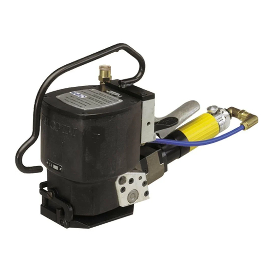
OPERATION MANUAL / SPARE PARTS LIST
PNEUMATIC
STEEL STRAPPING TOOL
MODEL A3H.0003
13.6090.02
CE Declaration of conformity
We declare that the machine A3H
is in conformity with the following standard or
standardised documents:
98/37/EEC
FROMM Holding AG
Hinterbergstrasse 26
CH - 6330 Cham
28.02 2005
R.Fromm
Director
For Parts & Service 1-877-862-6699
Advertisement
Table of Contents

Related Manuals for Fromm A3H.0003


Summary of Contents for Fromm A3H.0003
- Page 1 OPERATION MANUAL / SPARE PARTS LIST PNEUMATIC STEEL STRAPPING TOOL MODEL A3H.0003 13.6090.02 CE Declaration of conformity We declare that the machine A3H is in conformity with the following standard or standardised documents: 98/37/EEC FROMM Holding AG Hinterbergstrasse 26 CH - 6330 Cham 28.02 2005...
-
Page 2: Table Of Contents
A3H.0003 ..........6 A3H.0003/D (with a throttle valve)....... 6 OPERATION Feeding the strap around the package . -
Page 3: Safety Instructions
SAFETY INSTRUCTIONS Read these instructions carefully. Failure to follow these instructions can result in severe personal injury. Eye injury hazard Strap breakage hazard Failure to wear safety glasses with side shields can result in Improper operation of the tool, excessive tensioning, using strap severe eye injury or blindness. -
Page 4: Warranty Conditions And Liability
WARRANTY CONDITIONS AND LIABILITY FROMM Holding AG warrants all its strapping tools and machine heads during a period of 90 days from the date of sale. The warranty includes all deficiencies clearly resulting from poor manufacturing or faulty materials. Damage claims as a result of production shutdowns and claims for damage to persons and to property resulting from warranty deficiencies cannot be asserted by the customer. -
Page 5: Compressed Air
Compressed air Joining thread: G 1/4" Air-tube: Min. inside diam. = 8 mm / 5/16" Max. air pressure: 5 bar / 70 psi Air consumption: Tensioning Sealing 450 Nl / 15.8 cu.ft per minute with the 5 Nl / 0.17 cu.ft per cycle air motor running. -
Page 6: Chart Of Types
2500 N / 560 lbs 170 mm / s 13.6130 A3H/20/0.38-0.60/4.5 20 mm 0.38-0.60 mm / .015-.024" 4500 N / 1010 lbs 100 mm / s A3H.0003/D (throttle valve) Item No. Model Strap width Strap thickness Max.Tension Tension. speed 13.6056 A3H/9.5/0.38-0.60/2.5/D... -
Page 7: Operation
OPERATION Feeding the strap around the package The strap is fed around the package in the direction as shown in the illustration. The end of the strap is held tightly with the left hand and pulled firmly towards the operator with the right hand. -
Page 8: Sealing The Strap
Throttle valve On all tools provided with the throttle valve the air supply can be adjusted on the throttle screw A3H.1810. Sealing the strap Press the valve lever with the thumb of the right hand until the seal is done. Removing the tool from the tensioned and sealed strap. -
Page 9: Seal Control
SEAL CONTROL A regular control of the seal is necessary. The seal can be checked visually and the person controlling can easily judge the quality of the seal. When checking the seal the following illustrations must be compared. Correct seal A correct seal must be conform to the illustration. - Page 10 A3H.1803 A3H.1811 N1.1111 N1.1111 N2.4902 N1.6207 A3H.1116 N1.2102 N41.9128 N2.4902 N41.9124 A3H.1103 N6.6203 N1.6601 N1.5502 N6.6103 N6.6301 A3H.1301 N6.5102 N6.6104 N6.5101 A3H.1302 N1.1111 N4.5101 N6.5108 A3H.1205 A3H.1802 N2.5122 N6.5107 N2.1301 V1.1114 A.1223 N2.5601 N1.1166 N2.2110 V1.1106 A3H.1204 N2.5102 A3H.1113 A3H.1202 N1.6207 V1.1110 A.1222...
- Page 11 Loctite 542 Loctite 222 Oil SAE 20 Molycote BR2 plus N6.5104 N6.5108 N6.5104 Mobilux EP2 40 Nm L2.1101 60 Nm N6.5101 A3H.1607 N6.5102 N2.5602 A3H.1809 N2.2103 N3.2304 A3H.1601 A3H.1602 A3H.1603 A3H.1606 A3H.1610 A3H.1422 N3.2104 N2.2103 N3.2304 N1.2102 A3H.1405 A3H.1605 A3H.1412 N1.2106 A3H.1602 A3H.1407...
-
Page 12: Spare Parts List 13.6090.02
SPARE PARTS LIST 13.6090.02 13.6090.02 A3H/16/0.38-0.60/4.5 A3H.0003.02 22.02.06 Item-No. in group Pcs. Description Dimension Field A3H.1103 1 CYLINDER COVER A3H.1104 1 STRAP GUIDE LEVER A3H.1106 1 STRAP LIMITER A3H.1109 1 GUIDE KEY A3H.1110 1 FILTER NETTING A3H.1111 1 NETTING FRAME A3H.1112... - Page 13 13.6090.02 A3H/16/0.38-0.60/4.5 A3H.0003.02 22.02.06 Item-No. in group Pcs. Description Dimension Field A.1103 1 PUNCH A.1222 1 DIE A.1223 1 SHEAR BLADE [L2.1101] 1 AIR MOTOR [L2.1103] L2.1101 1 PLANET SHAFT L2.1201 L2.1101 1 EXHAUST RING L2.1203 L2.1212 1 PLASTIC JACKET L2.1206...
- Page 14 13.6090.02 A3H/16/0.38-0.60/4.5 A3H.0003.02 22.02.06 Item-No. in group Pcs. Description Dimension Field N1.6207 7 SPRING LOCK WASHER N1.6207 A3H.1413 4 SPRING LOCK WASHER N1.6501 3 SAFETY WASHER N1.6502 1 SAFETY WASHER N1.6601 1 SCREW LOCKING N1.6701 L2.1101 2 TOOTH LOCK WASHER N2.1108...
- Page 15 13.6090.02 A3H/16/0.38-0.60/4.5 A3H.0003.02 22.02.06 Item-No. in group Pcs. Description Dimension Field N6.6201 L2.1101 1 O-RING 4.3 X 1.4 N6.6202 1 O-RING 25 X 2.5 N6.6203 1 O-RING 109 X 2 N6.6205 L2.1101 1 O-RING 9.2 X 1.78 N6.6206 L2.1101 1 O-RING 4.3 X 2.4...
-
Page 16: Seal Adjustment
10 SEAL ADJUSTMENT The sealing- and cutting depth of the sealing mechanism and the cutter can be adjusted with a screw driver by turning the adjusting screw A3H.1709. Sealing depth is excessive Turning the adjusting screw A3H.1709 clockwise reduces the sealing depth. A turn of 90° equals adjustment of 0.25 mm / .010". -
Page 17: Control Of Oil Level
11.4 Control of oil level According to the use of the tool the oil-level must N1.1111 be checked periodically and the inside of the cylinder must be cleaned at the same time. This Suspension Suspension bracket oil control is necessary because it prevents that due to oil losses over a certain period of time the sealing mechanism does not reach the necessary stroke. -
Page 18: Tensioning Wheel
12.2 Tensioning wheel The tensioning wheel should be exchanged if its teeth are dull and the wheel revolves without transporting the strap. Procedure: • Unscrew the screws N1.1113 and disassemble the end cover. • Disassemble the security ring N2.1108. • Disassemble the spacer ring A3H.1504 and the tensioning wheel A3H.1503. -
Page 19: Punch And Die
12.4 Punch and die If it‘s impossible to make a correct seal although the adjustment of the adjusting screw is correct (see SEAL CONTROL) the base plate has to be disassembled and the wearing of the stamp tools has to be checked. If the cutting edges are damaged or blunted (Attention! The cutting edges are also slightly rounded off when they are new) the used parts have to be exchanged.
Need help?
Do you have a question about the A3H.0003 and is the answer not in the manual?
Questions and answers