
Related Manuals for Fromm P355.0001.01


Summary of Contents for Fromm P355.0001.01
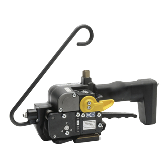
- Page 1 SERVICE MANUAL SERVICE MANUAL PNEUMATIC PLASTIC PNEUMATIC PLASTIC STRAPPING TOOL STRAPPING TOOL MODEL P355.0001.01 MODEL P355.0001.01 Manual for autorized dealers and service points...
-
Page 2: Table Of Contents
INDEX PAGE TECHNICAL DETAILS 1.1.1 Air supply........... . . 1-3 1.1.2 Pneumatic schematic . -
Page 3: Technical Details
TECHNICAL DETAILS 1.1 TECHNICAL DETAILS 1.1.1 Air supply 1/2" Shut off Valve 2" Pressure adjustment valve with Manometer Shut off Valve Filter with water separator Lubricator (app. 1-2 drops/min.) Drain of Main air line max. length 5m (16 ft.) min. Ø-inside 9mm (3/8") coupling G1/4 Air pressure: •... -
Page 4: Pneumatic Schematic
TECHNICAL DETAILS 1.1.2 Pneumatic schematic Pos. Description Pos. Description Pos. Description Tensioner valve Welding motor valve Valve lever for tensioning Tension force control valve Welding time valve Valve lever for welding Tensioning motor Welding motor Exhaust silencer Turn off valve Welding valve 1.1.3 Functional description A mechanical lock mechanism avoids simultaneous operation of tensioning and sealing lever. -
Page 5: Details Of The Pneumatic Control System
TECHNICAL DETAILS 1.1.4 Details of the pneumatic control system (Valve numbers correspond to the pneumatic schematic) Valve lever for tensioning Tensioner valve Tensioning motor... - Page 6 TECHNICAL DETAILS Valve lever for welding Welding valve Exhaust silencer Tension force control valve Welding motor Turn off valve Welding motor valve Welding time valve...
-
Page 7: Conversion Parts
CONVERSION PARTS 1.2 CONVERSION PARTS When changing strap thickness or strap width following parts must be exchanged. 1.2.1 Conversion parts: strap width 10mm 11.1mm 12mm 12.7mm 13mm 15mm 15.5mm 16mm Guide P30.1156 P30.1158 P30.1156 P30.1157 P30.1158 P30.1159 P30.1160 P30.1161 Guide P30.1162 P30.1164 P30.1162... -
Page 8: Periodic Maintenance And Control
PERIODIC MAINTENANCE AND CONTROL 1.3 PERIODIC MAINTENANCE AND CONTROL Carry out 12- months cycles doing one shift work. Doing multiple shift work respectively more often. 1.3.1 Procedure Before using check tool for following possible faults: • Visual test of the tool for loose, lost or damaged parts •... -
Page 9: Troubleshooting
PERIODIC MAINTENANCE AND CONTROL 1.3.2 Troubleshooting A sufficient compressed air supply and the use of the tool’s specific strap should be guaranteed before each tool repair. SYMPTOM CAUSE REMEDY Tool doesn’t tension, The tensioning wheel is packed with Clean tensioning wheel with Tensioning motor runs strap residue or is worn and mills on compressed air or replace it... -
Page 10: Checklist
PERIODIC MAINTENANCE AND CONTROL SYMPTOM CAUSE REMEDY Tool badly cuts the strap or Cutter is worn or damaged Replace cutter doesn’t cut at all Wrong adjustment of the coupler Check adjustment and readjust if P32.1250 necessary (see operation manual P355) Welding gripper is worn Replace welding gripper Welding time too short... -
Page 11: Glueing Rules
PERIODIC MAINTENANCE AND CONTROL 1.3.4 Glueing rules Following parts have to be glued with LOCTITE 603: N2.2145 Planet shaft P32.1044 with the parallel pins N2.2145. P32.1044 Tensioning body P32.1254 with the parallel pins N2.2189 Body P35.2002 with swivel shaft P35.2004 and parallel pins N2.2188 P32.1254 N2.2189... -
Page 12: Assembly Information
PERIODIC MAINTENANCE AND CONTROL All movable gear parts have to be lubricated with MOLYKOTE BR 2 PLUS grease. Lubrication interval: At each maintenance or after 12 months at the latest. All other parts have to be greased according to the explosion drawing. Lubrication interval: At each maintenance or after 12 months at the latest. - Page 13 PERIODIC MAINTENANCE AND CONTROL Grippers: When installing the grippers into the tensioning body P32.1254 pay attention to the direction of the teeth.(see picture) P32.1254 Grippers Cup springs: Assemble the cup springs N2.5621 as shown in the picture. N2.2443 N2.5621(14X) P32.1030 P32.1031 Motor cover: P35.2028...
-
Page 14: Recommended Spare Parts
RECOMMENDED SPARE PARTS Gear body: When assembling or disassembling the P35.2007 gear body (P35.2034) the touch bolt (P35.2007) and the guide (P35.2006) of P35.2006 the welding valve must be pressed down. The spring N2.5822 must be slightly lifted up. (see drawing) N2.5822 P35.2034 1.4 RECOMMENDED SPARE PARTS... -
Page 15: Accessory Tools
ACCESSORY TOOLS 1.5 ACCESSORY TOOLS Item Field number N7.3219 Press in and press out pressure pad for N3.3173/P35.2002 N71.3235 Press in and press out arbor for N3.4509/P35.2036 N71.3237 Press in and press out arbor for N3.1159/P32.1037 N71.3238 Press in and press out pressure pad for N3.1159/P32.1037 N71.3239 Press in arbor for N3.2347/P32.1024 N71.3240... -
Page 16: Use Of Accessory Tools
ACCESSORY TOOLS 1.5.1 Use of accessory tools Accessory tools should only be used with the suitable arbor press N7.5108 N7.5108 in order to avoid a tilt of the pressed in parts. Additional a retainer (N7.3215) is necessary. N7.3215 Part Disassembly Assembly N3.1157/ P32.1044... - Page 17 ACCESSORY TOOLS Part Disassembly Assembly N3.1159/ P32.1037 N71.3237 N3.1159 P32.1037 N71.3238 N3.3172/ N71.3248 P32.1254 N71.3250 N3.3172 N71.3249 P32.1254 N3.4509/ N71.3235 P35.2036 N3.4509* P35.2036 N71.3273 *Assembling position see „Assembly information“ 1-17...
- Page 18 ACCESSORY TOOLS Part Disassembly Assembly P32.1023/ N3.1134/ N71.3243 N71.3244 P32.1022 P32.1022 N3.1134 N71.3245 P32.1023 N3.2347/ N71.3239 P32.1024 N71.3240 N3.2347 P32.1024 N71.3241 The seal of the needle bushing (N3.2347) has to face to the outside N3.2346/ P32.1238 N71.3242 N3.2346 P32.1238 N71.3245 1-18...
- Page 19 ACCESSORY TOOLS Part Disassembly Assembly P32.1123/ P35.0123 Picture 1 N71.3244 P32.1023/ P35.0124 N71.3254 P32.1023/1123 N71.3280 P35.0123/0124 N71.3255 Picture 2 N71.3275 1-19...
- Page 20 ACCESSORY TOOLS Part Disassembly Assembly N3.3173/ P35.2002 N71.3253 N71.3254 N3.3173 P35.2002 N7.3219 N7.3219 Part Disassembly Assembly P35.2023/ N3.1174/ P35.2021 Commercially available Puller. N71.3277 The distance between rotor (P35.2021) and end plate (P35.2023) should be 0,03 mm P35.2021 P35.2023 N3.1174 N71.3276 1-20...
- Page 21 ACCESSORY TOOLS Part Disassembly P35.2005/ Picture 2 Coupler P35.2002 Picture 1 N71.3274 Clip P35.2002 P35.2005 Ball seat Attention! When disassembling the valves do not damage the ball seat of the exhaust ring P35.2005. Procedure: • Press clip together and insert it into the hole, until it engages in the exhaust ring (P35.2005) •...
-
Page 22: Ordering Spare Parts
Dutch "de" (see table). Portuguese Swedish Finnish 1.6.2 Ordering address Spanish Spare parts and manuals can be ordered at: Fromm Holding AG Tel.: +41(0) 41 741 57 41 Hinterbergstrasse 26 Fax: +41(0) 41 741 57 60 CH-6330 Cham e-mail: orders@fromm-pack.com... -
Page 23: Finding Out Of The Tool Type (Item Number), The Serial Number And The Version Number
Version number U.S.PATENT No.6405776 U.S.PATENT No.6463847 1.7 SERVICE ADDRESS You will get further assistance and information at: Post address Physical address: Fromm System GmbH Fromm System GmbH Technical customer support Technical customer support Postfach 12 46 Neulandstr. 10 D-77843 Achern... - Page 24 SERVICE ADDRESS 1-24...
- Page 25 DRAWINGS P355.0001.01 P355.0001.01.z1.en.fm...
- Page 26 P355.0001.01.z...
- Page 27 P355.0001.01.z3.en.fm...
- Page 28 P355.0001.01.z...
- Page 29 SPARE PARTS LIST P355 3.1 Type independent spare parts P355.0001.01 Item-No. in group Pcs. Description Dimension Field N1.1106 P35.0127 2 SCREW M6 X 20 N1.1151 P35.0122 2 SCREW M6 X 80 N1.1305 2 SCREW M4 X 7.8 N1.1553 P32.1250 1 HEXAGON SCREW M4 X 8 N1.1813...
- Page 30 1 ADHESIVE LABEL 20 X 10 X 0.1 N41.9129 1 ADHESIVE LABEL p max. 6 bar/87 psi N41.9143 1 TYPE PLATE >>P355<< N4.9108 1 ADHESIVE LABEL 54 X 12 X 0.1 [ ] = Group * = Wearing parts P355.0001.01.ee...
- Page 31 3 IDLER GEAR P32.1047 P32.0118 1 COVER P32.1048 P32.0120 1 WHEEL P32.1049 P32.0119 1 SPUR WHEEL P32.1050 P35.0120 1 FRONT TOGGLE LINK P32.1051 P35.0120 1 LEVER P32.1053 P35.0120 1 WELDING GRIPPER [ ] = Group * = Wearing parts P355.0001.01.ee...
- Page 32 1 JACKET P35.2021 P35.0123 1 ROTOR P35.2021 P35.0124 1 ROTOR P35.2022 P35.0123 10 FELT P35.2022 P35.0124 10 FELT P35.2023 P35.0123 1 END PLATE P35.2023 P35.0124 1 END PLATE P35.2024 P35.0123 5 VANE [ ] = Group * = Wearing parts P355.0001.01.ee...
- Page 33 P35.2065 P35.0120 1 AIR CONNECTION [P35.2066] P35.0127 1 COVER P35.2067 P35.0125 1 BOLT P35.2068 P35.0125 1 FLANGE P35.2069 P35.0125 2 RATCHET DISK [P35.2070] P35.0125 1 SUSPENSION BRACKET P35.2073 P35.0125 1 DISK [ ] = Group * = Wearing parts P355.0001.01.ee...
- Page 34 [ ] = Group * = Wearing parts P355.0001.01.ee...
- Page 35 3.2 Type dependent spare parts P355.0001.01 Type 49.0301.01 49.0301.01 P355/10/0.40-0.64 P355.0001.01 28.03.02 Description Dimension Field Item-No. in group Pcs. P30.1156 1 GUIDE PIN P30.1162 1 GUIDE PIN P32.1201 1 STEEL INSERT P32.1205 1 GUIDE CASE P32.1219 1 TENSIONING WHEEL P32.1222 1 GRIPPER P32.1223...
- Page 36 Type 49.0312.01 49.0312.01 P355/11.1/0.65-1.05 P355.0001.01 28.03.02 Description Dimension Field Item-No. in group Pcs. P30.1158 1 GUIDE PIN P30.1164 1 GUIDE PIN P32.1202 1 STEEL INSERT P32.1205 1 GUIDE CASE P32.1220 1 TENSIONING WHEEL P32.1225 1 GRIPPER P32.1226 1 GRIPPER P32.1227 1 GRIPPER P32.1231...
- Page 37 Type 49.0323.01 49.0323.01 P355/12.7/0.40-0.64 P355.0001.01 28.03.02 Description Dimension Field Item-No. in group Pcs. P30.1157 1 GUIDE PIN P30.1163 1 GUIDE PIN P32.1201 1 STEEL INSERT P32.1206 1 GUIDE CASE P32.1219 1 TENSIONING WHEEL P32.1222 1 GRIPPER P32.1223 1 GRIPPER P32.1224 1 GRIPPER P32.1233...
- Page 38 Type 49.0332.01 49.0332.01 P355/13/0.65-1.05 P355.0001.01 28.03.02 Description Dimension Field Item-No. in group Pcs. P30.1158 1 GUIDE PIN P30.1164 1 GUIDE PIN P32.1202 1 STEEL INSERT P32.1206 1 GUIDE CASE P32.1220 1 TENSIONING WHEEL P32.1225 1 GRIPPER P32.1226 1 GRIPPER P32.1227 1 GRIPPER P32.1234...
- Page 39 Type 49.0353.01 49.0353.01 P355/15.5/0.40-0.64 P355.0001.01 28.03.02 Description Dimension Field Item-No. in group Pcs. P30.1160 1 GUIDE PIN P30.1166 1 GUIDE PIN P32.1201 1 STEEL INSERT P32.1206 1 GUIDE CASE P32.1219 1 TENSIONING WHEEL P32.1222 1 GRIPPER P32.1223 1 GRIPPER P32.1224 1 GRIPPER P32.1236...
- Page 40 Type 49.0362.01 49.0362.01 P355/16/0.65-1.05 P355.0001.01 28.03.02 Description Dimension Field Item-No. in group Pcs. P30.1161 1 GUIDE PIN P30.1167 1 GUIDE PIN P32.1202 1 STEEL INSERT P32.1206 1 GUIDE CASE P32.1220 1 TENSIONING WHEEL P32.1225 1 GRIPPER P32.1226 1 GRIPPER P32.1227 1 GRIPPER P32.1237...
- Page 41 PNEUMATIC PLASTIC STRAPPING TOOL MODEL P355 CE Declaration of conformity We declare that the machine P355 is in conformity with the following standard or standardised documents: 98/37/EEC FROMM Holding AG Hinterbergstrasse 26 CH - 6330 Cham 22.01 2002 R.Fromm Director...
- Page 42 INDEX PAGE SAFETY INSTRUCTIONS TECHNICAL DATA CHART OF TYPES WARRANTY CONDITIONS AND LIABILITY APPROPRIATE USE INSTALLATION 4.6.1 Compressed air connection........4-6 4.6.2 Accessories .
-
Page 43: Safety Instructions
4.1 SAFETY INSTRUCTIONS Read these instructions carefully. Failure to follow these instructions can result in severe personal injury. Eye injury hazard Strap breakage hazard Failure to wear safety glasses with side shields can result Improper operation of the tool, excessive tensioning, using in severe eye injury or blindness. -
Page 44: Technical Data
4.2 TECHNICAL DATA Description of the tool The tool model P355 has been designed to strap packages with plastic strapping. The plastic strapping is fed around the package manually or in combination with a strap feeder. The straps are inserted in the tool, automatically tensioned, sealed by friction welding and separated. -
Page 45: Chart Of Types
4.4 WARRANTY CONDITIONS AND LIABILITY FROMM Holding AG warrants all its strapping tools and machine heads during a period of 24 months from the date of installation at the end-user's sight by the distributor, however, not later than 30 months from the date of shipment to the distributor of FROMM Holding AG. -
Page 46: Installation
4.6 INSTALLATION 4.6.1 Compressed air connection The compressed air is to be connected to the tool preferably by a quick disconnector (G1/4). An air-unit consisting of a separator for water and dirt, a pressure regulator with a manometer and a lubricator must be installed within a range of 15 ft / 5 meters. - Page 47 Suspension of tool It is possible to suspend the tool on a spring loaded balancer using the suspension bracket P35.0125 which is supplied with the tool. The suspension bracket has been designed in such a way, that the tool can be used for all three working positions.
-
Page 48: Adjustments
4.6.3 Adjustments 4.6.4 Preselecting of strap tension and tensioning speed Do not adjust the tensioning force too high. If the tensioning force is higher than the tensioning strength of the strap, the strap will tear while the tensioning. Tensioning force and tensioning speed can be preselected at the control head. -
Page 49: Operating Elements
4.7 OPERATING ELEMENTS Tensioner valve lever Lever Handle lever 4.8 OPERATION 4.8.1 Feeding the strap around the package The strapping is fed around the package as illustrated. Warning! The plastic strap which will be welded must be free from oil, grease and other dirt. -
Page 50: Inserting The Strap
4.8.2 Inserting the strap Pull up the handle lever firmly with your right hand. Insert the two straps well aligned on each other into the strap guide using your left hand. Release the handle lever. 4.8.3 Tensioning the strap Press down the tensioner valve lever and then release it again after the desired strap tension has been reached. -
Page 51: Sealing The Straps
4.8.4 Sealing the straps While welding the plastic strap the lever must be pressed forward against the front stop After the welding operation the lever must be pressed against the front stop for another 1-2 seconds until the seal is cooled down. Disregarding of this regulation will cause insufficient seal efficiency, what can cause severest injuries. -
Page 52: Exchange Of Wearing Parts
4.9 EXCHANGE OF WEARING PARTS Before any maintenance work always disconnect the tool from the air supply. 4.9.1 Exchange of tensioning wheel and grippers Disassembling • Unscrew end cover P32.1238 and remove it; • Remove the torsion spring N2.5823; • Remove the tensioning body P32.1254;... -
Page 53: Exchange Of Cutter, Welding Stop Gripper And Welding Gripper
4.9.2 Exchange of cutter, welding stop gripper and welding gripper Disassembling • Unscrew cover P32.1211 and remove it; • Unscrew end cover P32.1238 and remove it; • Disassemble security ring N2.1118, pull the grip axle P35.2064 from the tool; • Tilt down the handle lever P32.1212 and remove it from the tool;... -
Page 54: Adjustment Of The Coupler P32.1250
Assembling Assembling in opposite order. Observe the following: • Pay attention to the proper seat of the thrust piece on the spring bolt P32.1030 when lifting the rocker. • Pay attention to the fitting position of the cutter (see drawing). •...
Need help?
Do you have a question about the P355.0001.01 and is the answer not in the manual?
Questions and answers