Table of Contents
Advertisement
Quick Links
Advertisement
Table of Contents

Subscribe to Our Youtube Channel
Related Manuals for Blastrac BMS-150


Summary of Contents for Blastrac BMS-150
- Page 1 SERVICE MANUAL BMS-150 VERSION 1.1...
-
Page 2: Inspection Comments
Inspection comments Inspection before initial operation on: Date of initial operation: Serial number & Year of manufacture: Recurring inspections / maintenance log Date / Hour counter Findings Repairs / Cleaning Test *Competent person... -
Page 3: Table Of Contents
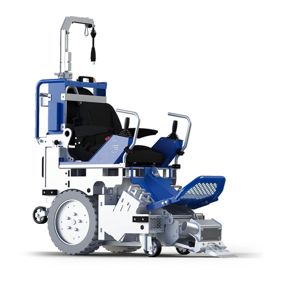
Mount axle in the lifting arm 14.3 Removing the lifting arm 14.4 Remove drive motor 14.5 Remove joystick from the BMS-150 14.6 Adjust the spring tension of the cable reel 14.7 Changing the spring of the cable reel 14.8 Changing the electric cable... - Page 4 Fig. 01 BMS-150 Overview...
- Page 5 Fig. 01 BMS-150 Overview Item Blastrac PN HQV PN Description Qty. BE1129 534778901 Protection cap Ø22 BMS-150 E14772 Joystick protection bar 534647601 999-9150 Pipe clamp (set) 1530022P 22mm Black 534757201 E13970 Main frame BMS-150 535211201 E14768 Protection strip 534781301 E14291...
- Page 6 Fig. 02 Swivel arm (Rotating arm)
- Page 7 Fig. 02 Swivel arm (Rotating arm) Item Blastrac PN HQV PN Description Qty. E08473 Plug 230V 16A 534767501 E14344 Cable cable end 534378801 BE0653 Hook 6x60mm 533214001 E14262-1 534888301 Swivel pipe for electro cable M8x60 Hexagon bolt E14777 535207001 Lockplate cable reel...
- Page 8 Fig. 03 Swivel arm (cable roll bracket)
- Page 9 Fig. 03 Swivel arm (cable roll bracket) Item Blastrac PN HQV PN Description Qty. E14384 Connection strip 535152001 E14344 534378801 Cable reel 25 mtr. E14278 Cable roll Bracket 535145701 E12966 534616801 Handle 8.5 x151 E17457 Signal lamp HAA40AN Orange 534843001...
- Page 10 Fig. 04 Top frame...
- Page 11 Fig. 04 Top frame Item Blastrac PN HQV PN Description Qty. E14253 Top frame 535256301 E1387 533925001 Complete seat M6x10 hexagon socket button head screw with flange M12x40 Hexagon bolt M12 spring lock washer M12 plain washer E11543 Mounting bush...
- Page 12 Fig. 05 Drive wheels (left and right)
- Page 13 Blastrac PN HQV PN Description Qty. 222-2471-UB Pivot bearing FY 40 TR 534361001 Key 8x7x100 E13971 Driving axle 535165901 E09169 Wheel complete BMS-150 533768901 BE0026 M12 plain washer 533250701 BE0027 M12 spring lock washer 533288701 BE0036 M12x40 Hexagon head screw 533855701...
- Page 14 Fig. 06 Motor compartment...
- Page 15 E13966 Drive motor 1,1kW 3x230/400V 50/60Hz 534700401 E14295 Actuator mounting bracket 534260701 E14444 Distance axle 534672901 E13970 Main frame BMS-150 535211201 E14277 Led light 534662401 E15580 Headlight cover 535192201 Valid from SERIAL NUMBERS 32007 B and HIGHER: Item Blastrac PN...
- Page 16 Fig. 07 Cutting head...
- Page 17 Fig. 07 Cutting head Item Blastrac PN HQV PN Description Qty. E14399 Lifting arm 534674701 E14411 Electric cylinder 534542101 E14652 Rod end male M12 534810901 E14420 Limit switch bracket 535204501 E05003 Limit switch 533296001 BE0727 SHIM 1,0 MM 12X24MM BE1130...
- Page 18 Fig. 08 Wheel hub Fig. 08 Wheel hub Item Blastrac PN HQV PN Description Qty. E14423 Anti-slip E14256 Wheel Hub 535270501 E14256_4 Distance bush BE1123 M10 12x12 hexagon shoulder bolt 534676201 BE0026 M12 plain washer 533250701 M12x80 Hexagon bolt E14292...
- Page 19 Fig. 09 Controls...
- Page 20 Fig. 09 Controls Item Blastrac PN HQV PN Description Qty. E17459 Robust Joystick 535640201 E17455 Round green illuminated pushbutton push to release E17458 Marquardt Toggle switch E14269 Plate E14290 Back plate 535074801 M5x10 Hexagon socket button head screw with flange...
- Page 21 Fig. 10 Blades E09500 E09501 E09502 E09503 E09504 Blastrac HQV PN 534595802 534595802 534595802 534595802 534595802 Heavy Duty Heavy Duty Heavy Duty Heavy Duty Heavy Duty Blade 152 x 76 x Blade 203 x 76 x Blade 254 x 76 x...
- Page 22 Fig. 12 Chisels E09540 E09542 E09550 E09552 Blastrac HQV PN 533858501 533865601 533127801 533128001 Premium Chisel 51 x Premium Chisel 152 x Heavy Duty Chisel 51 x Heavy Duty Chisel 152 x 12 mm 12 mm 12 mm 12 mm Fig.
-
Page 23: Dismounting The Cylinders
Make sure the machine is standing stable on the ground. And prevent the BMS-150 of tilting. 14.1 Dismounting the cylinders. Make sure the Cable system is folded down. (see chapter 5.5 from the manual Folding the BMS-150) # Cable system folded down. - Page 24 Tilt the top frame. And secure the top frame by using the M12 bolt. PUT IN M12 Bolt Unscrew the Bolt from the actuator mounting bracket.
- Page 25 Unscrew the bolt from the lifting arm. Disconnect the plug. Now you can remove the cylinder from the BMS-150.
- Page 26 Dismount the cylinder used for changing the angle of the tool. Disconnect the plug. Unscrew the highlighted bolt from the bracket. - Unscrew the highlighted bolt.
- Page 27 Remove the cylinder from the BMS-150...
-
Page 28: Mount Axle In The Lifting Arm
14.2 Mount axle in the lifting arm. When the cylinder is not functioning. You can still work when you mount the axle. First take out the cylinder. Chapter 14.1. Take out the axle. Highlighted in green. Mount the axle in the holes of the lifting arm and frame and secure the axle with 2 pins. -
Page 29: Removing The Lifting Arm
14.3 Removing the lifting arm. Make sure the Cable system is folded down. (see chapter “Folding the BMS-150” in the Operation Instruction Manual). # Cable system folded down. Dismount the M12 bolt. - Page 30 Tilt the top frame. And secure the top frame by using the M12 bolt. PUT IN M12 Bolt Remove the highlighted Bolts. Left and right.
- Page 31 Unscrew the Bolt from the lifting arm.
- Page 32 Remove the lifting arm from the BMS-150. For easier moving the lifting, insert a lifting bolt M10. So you can lift the lifting arm with a crane.
-
Page 33: Remove Drive Motor
14.4 Remove drive motor. Make sure the Cable system is folded down. (see chapter “Folding the BMS-150” in the Operation Instruction Manual). Make sure the BMS-150 is stable! # Cable system folded down. Dismount the M12 bolt. - Page 34 Tilt the top frame. And secure the top frame by using the M12 bolt. PUT IN M12 Bolt Unscrew the highlighted bolts...
- Page 35 Make sure the BMS-150 is stable and you can safely remove the wheel, without the risk of tilting. For example: Use a piece of wood to support the BMS-150 Remove the wheel from the BMS-150 CHANGING THE JOYSTICK. Make sure the main plug is pulled out of the power source.
- Page 36 Remove the wheel axle and bearing from the BMS-150. Unscrew the bolts from the drive motor. UNSCREW THE 4 BOLTS...
- Page 37 Disconnect the wires of the motor. Remove the drive motor from the BMS-150. # Note. To remove the other drive motor, you first need to remove the lifting arm. Chapter 14.3 Removing the lifting arm.
-
Page 38: Remove Joystick From The Bms-150
14.5 Remove joystick from the BMS-150 # Cable system folded down. Dismount the M12 bolt. - Page 39 Tilt the top frame. And secure the top frame by using the M12 bolt. PUT IN M12 Bolt Remove the highlighted plate by unscrewing the 4 M5x10 bolts.
- Page 40 Unscrew the highlighted M5x10 Bolts(4). Pull out the joystick. - Remove the joystick from the bottom plate. By unscrewing the 4 bolts. Dis-connect the plug of the joystick.
-
Page 41: Adjust The Spring Tension Of The Cable Reel
14.6 Adjust the spring tension of the cable reel. Remove the two connection strips. And move the seat forwards. Make sure the cable is in place and fully recoiled on the cable reel. Insert an tommy bar and hold the tommy bar firmly. Then remove the two screws, and turn in the direction of the arrow as shown in the picture (counter clock wise). -
Page 42: Changing The Spring Of The Cable Reel
14.7 Changing the spring of the cable reel. Remove the two connection strips. And move the seat forwards. Make sure the cable is in place and fully recoiled on the cable reel. - Page 43 Step 1. Loosen the intake cable from the swivel. Dismantle the reel from the BMS-150 Dismantle the drum from the stand. Step 2. Remove the spring hub. Step 3. Remove the cover from the spring. NOTE! Check the rivet which holds the spring together and is positioned at the spring periphery.
- Page 44 Step 4. Fit the plastic stripes to the spring. The stripes comes in the package together with the new spring. Step 5. Remove the damaged spring.
- Page 45 Remount the drum in the stand. Put the cable through the outlet and mount the cable stop. Step 9. Mount the reel back on the BMS-150. Step 10. Tighten the spring by turning the hub with a tommy bar, 2-4 turns. Chapter 14.6.
-
Page 46: Changing The Electric Cable
14.8 Changing the electric cable... - Page 47 Step by step Instructions 1. Disconnect the powewr supply before the reel is dismanted 2. Disconnect the inlet cable from the reel. 3. Remove the reel from the cable system 4. Remove the cable stop. Let the cable coil on to the drum. Count the number of revolutions that coil on the drum.
- Page 48 BLASTRAC EUROPE WE’RE READY TO ASSIST YOU! BLASTRAC THE NETHERLANDS BLASTRAC POLAND BLASTRAC FRANCE EUROPEAN HEAD OFFICE SALES & SERVICE CENTRE SALES & SERVICE CENTRE Utrechthaven 12 Golina, ul. Dworcowa 47E ZI - 29, Av. des Temps Modernes NL - 3433 PN Nieuwegein...
Need help?
Do you have a question about the BMS-150 and is the answer not in the manual?
Questions and answers