Table of Contents
Advertisement
Quick Links
Advertisement
Table of Contents

Related Manuals for Blastrac EBE 500 S


Summary of Contents for Blastrac EBE 500 S
- Page 1 Operating Instructions EBE 500 S MAN-EBE 500S-EN...
- Page 2 ISPC Blastrac/EBE Utrechthaven 12 3433 PN Nieuwegein THE NETHERLANDS T +31(0)30 - 601 88 66 F +31(0)30 - 601 83 33 E info@surfacepreparation.nl I www.surfacepreparation.com Technical data Safety instructions Nieuwegein General Transport Initial operation Operation Maintenance Electrical & hydraulic systems...
-
Page 3: Technical Data
EBE 500 S Operating Instructions Technical data Contents Chapter 1 1.1 Rating 1.2 Unit specifications 1.3 Operative range and correct usage 1.4 Stand-by power supply (generator 60 Hz) 1.5 Machine type designation 1.6 Advice for operators of blast cleaning machines... - Page 4 Operating Instructions EBE 500 S Technical data 1.1 Rating Unit / designation : ISPC Blastrac/EBE blast cleaning machine Machine type : EBE 500 S Manufacturer : ISPC Blastrac/EBE Utrechthaven 12 NL-3433PN Nieuwegein THE NETHERLANDS 1.2 Unit specifications Dimensions: Machine EBE 500 S...
- Page 5 Recommended filter unit : EBE 500 DAAM 1.3 Operative range and correct usage The EBE 500 S is exclusively designed to clean dry, frost-free horizontal surfaces. The machine may not be used for other purposes. The manufacturer will not be liable for damage resulting from such incorrect usage.
- Page 6 EBE 500 S Technical data 1.4 Stand-by power supply (generator 60 Hz) If the EBE 500 S blast cleaning machine is operated using a 60 Hz generator, this generator must be operated in accordance with the current VDE directives (this applies to the protective earth...
-
Page 7: Safety Instructions
EBE 500 S Operating Instructions Safety instructions Contents Chapter 2 2.0 Warnings and symbols 2.1 Organisational measures 2.2 Personnel selection and qualification 2.3 Safety precautions applicable to different operating conditions 2.4 Special work within the scope of use of the equipment and maintenance activities as well as repairs during operation 2.5 Definition of the Safety off position... - Page 8 Operating Instructions EBE 500 S Safety instructions 2.0 Warnings and symbols The following denominations and symbols are used in the Operating Instructions to highlight areas of particular importance: Symbol of operational safety. In these Operating Instructions this symbol will be shown next to all safety precautions that are to be taken in order to ensure prevention to life and injury.
- Page 9 EBE 500 S Operating Instructions Safety instructions Warning against dangerous voltages. Indications relating to protective devices in electrical appliances. Indications where consultation with manufacturer is required. Instructions relating to periodical checks. Reference to important instructions contained in the Operating Instructions.
- Page 10 Operating Instructions EBE 500 S Safety instructions The Operating Instructions must be supplemented by instructions including the duty to supervise and report relating to particular working practices, for example work organisation, work procedures and personnel allocation. Personnel entrusted with working with the machine must have read the Operating Instructions before starting work, in particular the Safety Instructions chapter.
- Page 11 EBE 500 S Operating Instructions Safety instructions To perform maintenance work correctly it is imperative to be equipped with the proper tools for the task in question. The location and the operation of fire extinguishers must be made known on each building site! Take note of the facilities for reporting and fighting fires! 2.2 Personnel selection and qualification...
- Page 12 Operating Instructions EBE 500 S Safety instructions 2.3 Safety precautions applicable to different operating conditions Ban any method of working that impairs safety! Only operate the machine when all safety devices and related safety equipment, e.g. detachable safety devices, emergency...
- Page 13 EBE 500 S Operating Instructions Safety instructions 2.4 Special work within the scope of use of the equipment and maintenance activities as well as repairs during operation Mechanical servicing work: Put the machine in the Safety off position as described in chapter 2.5 for any servicing work on the machine in order to prevent the...
- Page 14 Operating Instructions EBE 500 S Safety instructions 2.5 Definition of the Safety off position Definition: The machine is in a safe condition when it cannot generate any hazard. Putting the equipment in the Safety off position means: Close the valve.
-
Page 15: Danger Of Injury
EBE 500 S Operating Instructions Safety instructions 2.6 Particular dangerous aspects of the equipment Any machine, if it is not used according the regulations, may be hazardous for operating, setting-up and service personnel. The operating authority is responsible for compliance with the... - Page 16 Operating Instructions EBE 500 S Safety instructions 2.7 Electrical engineering regulations Work on electrical equipment or operating materials may only be undertaken by a skilled electrician or by trained persons under the guidance and supervision of a skilled electrician as well as in accordance with the electrical engineering regulations.
- Page 17 EBE 500 S Operating Instructions General Contents Chapter 3 Introduction Operating instructions Connections Care and maintenance Scope of supply Description Control box Operating elements Blast wheel 3.10 Separator and hopper 3.11 Hydraulic drive system 3.12 Abrasive sealing 3.13 Air suction and filter system...
- Page 18 General 3.1 Introduction ISPC Blastrac/EBE wants to thank you for your decision to employ the blast-cleaning machine EBE 500 S for the treatment of horizontal surfaces. The machine has a closed abrasive circuit with dust separation. This comprehensively avoids damaging the environment and endangering the operating staff.
- Page 19 A list of contents of the maintenance box is provided in Chapter 10 to enable the above-mentioned work to be carried out quickly. WARNING: BLASTRAC EBE machines build for the American market are especially build to run on 440-480V 60Hz. If the machines are operating on a Voltage or Hz lower than 440V and 60Hz, this will damage the electric components.
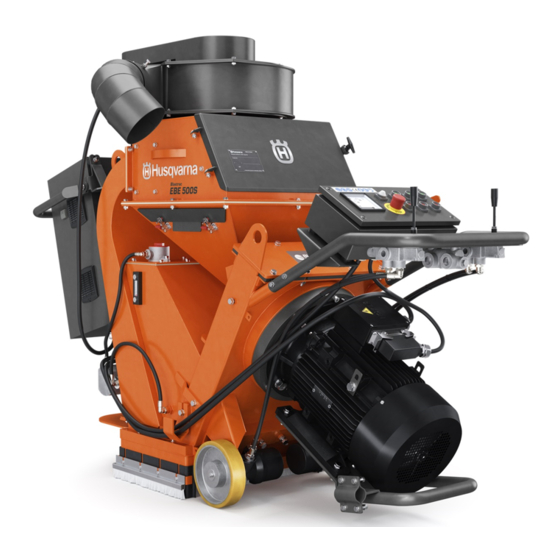
- Page 20 Operating Instructions EBE 500 S General 3.5 Scope of supply Scope of supply of the machine: Blast cleaning machine (EBE 500 S) Dust hose Operating instructions (2 x) Maintenance box (option) Magnetic broom (option) 3.6 Description Fig. 3.1 Fan unit...
- Page 21 EBE 500 S Operating Instructions General The ISPC Blastrac/EBE blast-cleaning machine EBE 500 S is a downward blasting machine with a closed abrasive circuit designed for the pre-treatment of horizontal surfaces. The bouncing impact of metallic abrasive onto the surface to be treated thoroughly removes surface contaminants, coats of paint, sealants and thin coatings.
-
Page 22: Control Handle
Operating Instructions EBE 500 S General 3.7 Control handle The control handle is equipped with all control elements and instruments for monitoring and controlling the blast cleaning machine. Fig. 3.3 Ammeter Push button “Drive OFF” Control lamp “Power” Push button “Fan OFF”... - Page 23 EBE 500 S Operating Instructions General Push buttons ”Drive ON/OFF” Pressing the push button "Drive ON" switches the drive control on. The machine can now move forward and backward by using the drive wheel joysticks. Pressing the push button "Control OFF" switches the drive control off.
-
Page 24: Operating Elements
Operating Instructions EBE 500 S General Ammeter The ammeter shows the load consumption of the blast wheel motor. When switching on the motor the current value is high (starting current peak) and falls, after having reached the idle speed, to approximately 10 A. - Page 25 EBE 500 S Operating Instructions General The shot valve handle This handle is located at the right side of the hopper and regulates the shot valve to control the flow of abrasive towards the blast wheel. When the handle is pulled upwards, the shot valve is opened and abrasive is allowed to travel towards the blast wheel in a progressive, controlled manner.
- Page 26 Operating Instructions EBE 500 S General 3.9 Blast wheel The heart of the blast-cleaning machine is a blast wheel that throws the abrasive onto the surface to be cleaned by using centrifugal force. The blast wheel is placed in a protective housing lined with replaceable wear parts.
- Page 27 EBE 500 S Operating Instructions General 3.10 Separator and hopper The abrasive separator is mounted to the end of the recovery duct. It separates the abrasive from contaminants and feeds the cleaned abrasive onto the abrasive storage hopper. Fig. 3.7...
- Page 28 Operating Instructions EBE 500 S General 3.11 Hydraulic drive system The drive is an independent hydraulic system contained within the ‘V’ of the blast housing cabinet. The hydraulic pump is driven by a small electric motor. There is an On and an Off switch on the control box to operate this motor.
- Page 29 EBE 500 S Operating Instructions General 3.12 Abrasive sealing The front seal system comprises of three polyurethane seals to ensure that good fit is maintained between the side seals and the work surface at the bottom. The seals are located in a seal box at the front of the blast opening of the cabinet and are clamped into place by bolts and plates.
- Page 30 Operating Instructions EBE 500 S General Side seal system: The side skirts and brushes are fixed to each side seal box with a plate and four screws. To replace them: unscrew the screws and remove the side skirts and brush and replace them if necessary.
- Page 31 EBE 500 S Operating Instructions General Place a drive ramp behind one of the drive wheels, position both directional control buttons in reverse, slowly turn the speed control clockwise and the machine will drive backwards on the drive ramp. When the side of machine is approx.
- Page 32 Operating Instructions EBE 500 S General 3.13 Air suction and filter system The air streaming through the complete system, created by exhaust fans (one on the dust arrestor, one on the machine), has the following functions: Cooling of the blast wheels...
- Page 33 EBE 500 S Operating Instructions General The air stream flows through the rebound plenum and carries along abrasive and dust. In doing so the air stream cools the abrasive and the housing walls. Fig. 3.12 The air enters the separator, separates the fine dust from the abrasive and transports the dust to the outlet opening.
- Page 34 EBE 500 S General 3.14 Abrasive media In order to operate the ISPC Blastrac/EBE machine EBE 500 S you need hardened (max. 45 Rockwell), spherical abrasive. The machine EBE 500 S has been especially designed to be operated with ISPC Blastrac/EBE abrasive.
- Page 35 EBE 500 S Operating Instructions General Selection of abrasive Abrasive shot S390 – S460: Standard abrasive, suitable for about 50-60 % of all applications. Creates a medium profile on concrete. Applications: removes laitance from new concrete roughening of smooth concrete or natural stone...
- Page 36 Operating Instructions EBE 500 S General The effectiveness of the EBE 500 S depends on the rebound effect which ensures that the abrasive can be re-used. Please take into account that the use of incorrect abrasive increases wear. Our service engineers have the experience to select the appropriate abrasive for the individual cases of application.
- Page 37 EBE 500 S Operating Instructions Transport Contents Chapter 4 4.1 General notes 4.2 Transport 4.3 Operation conditions 4.4 Operation 4.5 Unit specifications...
- Page 38 EBE 500 S Transport 4.1 General notes Before the machine is used for the first time, ISPC Blastrac/EBE authorised dealers offer a course to familiarise maintenance and operating personnel with all elements of the machine. We are not liable for damage caused by incorrect use of the machine by personnel not trained by ISPC Blastrac/EBE.
-
Page 39: Operation Conditions
EBE 500 S Operating Instructions Transport 4.3 Operation conditions Check the surface to be treated for loose parts (stones, screws, etc.) and fluids (water, oil, etc.). The surface must be swept and cleaned if necessary. Make sure that the machine can travel over all inequalities on the surface. -
Page 40: Initial Operation
EBE 500 S Operating Instructions Initial operation Contents Chapter 5 5.1 Preparations for initial operation 5.2 Initial operation... - Page 41 Operating Instructions EBE 500 S Initial operation 5.1 Preparations for initial operation Before switching on make sure that all existing protective housings are mounted and that the filter unit is connected correctly. All persons in the proximity of the machine must wear ear protectors, safety glasses with lateral protection as well as safety shoes.
- Page 42 EBE 500 S Operating Instructions Initial operation Check the tightness of the hose connections and the condition of the hose to the filter. Make sure the dust container of the filter unit is empty. Check the separator parts for wear and defects. Remove foreign bodies and dust deposits in order to prevent the separator from being blocked.
- Page 43 Operating Instructions EBE 500 S Initial operation Fill approx. 35 kg of the selected abrasive (see Chapter 3.14) into the abrasive storage hopper of the blast cleaning machine. The shot valve must be closed whilst doing this. Fill in abrasive here! Abrasive control lever in ”CLOSED”...
- Page 44 If the ammeter indicates a high load consumption after having reached the idle-running speed, the shot valve may be partially open or there may be another disturbance. Find out the cause of the disturbance and, if necessary, contact your ISPC Blastrac/EBE customer service engineer.
- Page 45 Operating Instructions EBE 500 S Initial operation Set the travel direction control joysticks to "forward" (working direction). Select the speed using the drive speed control. Fig. 5.2 When blast cleaning concrete the abrasive shot valve may only be opened when the blast cleaning machine is travelling! If the machine is at a standstill and the shot valve is open deep holes may be blasted into the concrete surface within seconds.
- Page 46 EBE 500 S Operating Instructions Initial operation An indication exceeding the full load value means overloading of the motor, whereas an indication below the full load value shows that there is not enough abrasive fed to the blast wheel. If necessary re-adjust the abrasive shot valve handle that operates the shot valve or refill the hopper with abrasive.
- Page 47 EBE 500 S Operating Instructions Operation Contents Chapter 6 6.1 Operation 6.2 Hydraulic drive system 6.3 Recommended blast paths 6.4 Switching-off the machine 6.5 What to do if a fault occurs 6.6 Safety shutdown 6.7 Restarting after a fault 6.8 Measures before and after long standstills...
-
Page 48: Hydraulic Drive System
Operation 6.1 Operation Normal start-up and operation of the blast machine EBE 500 S is no different from the procedure described in Chapter 5 “Initial operation”. Carry out blasting in parallel tracks in such a way that the dust hose and electric cable do not become twisted. - Page 49 EBE 500 S Operating Instructions Operation Directional control valves Controls the direction of hydraulic flow to the drive wheel motors. The control has a three position function; forward, reverse and neutral. Left and right controls are independent from each other, giving instant...
- Page 50 Operating Instructions EBE 500 S Operation 6.3 Recommended blast paths Position the filter unit near to a power supply connection. Place the blast cleaning machine near to the filter unit and spread out the hose as shown in fig. 6.1.
-
Page 51: Switching Off The Machine
Make sure that all turning machine parts have come to standstill before any inspection or maintenance works are started. When the ISPC Blastrac/EBE blast cleaning machine is put out of operation for a longer period of time, pull out the mains plug and... - Page 52 Operating Instructions EBE 500 S Operation 6.5 What to do if a fault occurs Irrespective of the following information, the local safety regulations are valid in any case for the operation of the machine. First put the machine to its Safety off position. After that start looking for the defect.
- Page 53 EBE 500 S Operating Instructions Operation 6.8 Measures before and after long standstills Standstill of the machine for a maximum of 3 months. Before a long standstill period Switch off the machine (see Chapter 6.4). Protect the electric motors from moisture, heat, dust and shocks.
-
Page 54: Maintenance
EBE 500 S Operating Instructions Maintenance Contents Chapter 7 7.1 Recommendations 7.2 Maintenance and inspection list 7.3 Repairing 7.4 The blast pattern 7.5 Setting the blast pattern 7.6 Setting the control cage 7.7 Wear parts 7.8 Blastwheel blades & Impeller replacement... - Page 55 Operating Instructions EBE 500 S Maintenance 7.1 Recommendations With maintenance and inspection works, please observe Chapter 2 "Safety instructions". Failures due to inadequate or incorrect maintenance may generate very high repair costs and long standstill periods of the machine. Regular maintenance is therefore imperative.
- Page 56 EBE 500 S Operating Instructions Maintenance 7.2 Maintenance and inspection list Operating hours/ Inspection points, maintenance time period instructions 12 h after repairing Check the efficiency of all safety devices. Check all accessible screw connections for tight seat. every 3 h...
- Page 57 As already mentioned in Chapter 5 “Initial operation” we recommend to execute the first repair works on the machine with the help of ISPC Blastrac/EBE personnel. With this your maintenance personnel gets the opportunity to be trained intensely. Only those repair works are described which occur within the context of maintenance or which are required to replace wear parts.
- Page 58 Correct adjustment of the control cage and thus of the blast pattern is the most important factor for optimum working with the EBE 500 S blast cleaning machine. Incorrect adjustment of the control cage results in very high wear and...
- Page 59 Operating Instructions EBE 500 S Maintenance Every time the control cage is replaced, the thread of the blast wheel fastening screw should be checked. Make sure that this screw will be tightened correctly. In addition, absolute care must be taken to clean the thread from dust and abrasive.
- Page 60 EBE 500 S Operating Instructions Maintenance The following 4 factors affect the blast pattern: Turning direction of the blast wheels: The turning direction of the blast wheel must correspond to the instructions on the housing (arrow indicating the turning direction).
- Page 61 Operating Instructions EBE 500 S Maintenance 7.6 Setting the control cage The adjustment is effected by loosening the cage clamps and turning the control cage in the suitable direction. The cast grooves on the control cage show the position of the control cage opening. The following adjustment standard value is valid: the control cage opening is approximately opposite to the throwing angle.
- Page 62 EBE 500 S Operating Instructions Maintenance Move the blast head of the blast machine onto a 5-8 mm thick steel plate and blast for 15 seconds at full amperage without moving the machine from the spot. Stop the abrasive flow and move the machine forward until the blasted area is accessible.
- Page 63 Operating Instructions EBE 500 S Maintenance 7.7 Wear parts The blast wheel parts Fig. 7.3 Cage clamp Control cage Impeller Blades (set of 6) Blast wheel...
- Page 64 EBE 500 S Operating Instructions Maintenance The liners Fig. 7.4 Top liner Right liner Left liner...
- Page 65 Operating Instructions EBE 500 S Maintenance 7.8 Blastwheel blades & Impeller replacement During operation the blast wheel blades and the impeller will wear. To replace worn components: Make sure the power unit is stopped and the main electricity supply disconnected.
- Page 66 EBE 500 S Operating Instructions Maintenance 7.9 Changing the liners Fig. 7.5 Top liner cover Top liner Side liner Unscrew the top liner cover and remove it. Take out the top liner. Loosen the fastening screws securing the left and the right-hand liners and take the side liners out of the blast housing.
- Page 67 EBE 500 S Operating Instructions Electrical & hydraulic systems Contents Chapter 8 8.1 Electric circuit diagrams 500-9110-UNI 8.2 Hydraulic circuit diagram...
- Page 68 Particulars: PROJECT Client USF BLASTRAC / EBE Name 500 SE - Blastmachine Supplier USF BLASTRAC / EBE SUPPLIER Contact Mr. A. van Houten Telephone +31(0)30-6018866 Draw.number PJ02.01598T1A Telefax +31(0)30-6018333 Order number Email info@usfebe.nl DATA Arch.number PJ02.01598T1A Calc.number Status As Built Start of project 06.02.2002...
- Page 69 24.04.2002 Main-voltage 24.04.2002 Main-voltage 24.04.2002 Control-voltage 24.07.2002 Terminal strip X2 24.07.2002 Terminal strip X3 24.07.2002 Start 06.02.2002 Arch.nr. USF BLASTRAC / EBE Table of contents PJ02.01598T1A Eng. 500 SE - Blastmachine Draw.nr. Pages Page Print 24.07.2002 PJ02.01598T1A Change Date Name...
- Page 70 -Dark blue -Grey Potential free and stranger-voltage: Revision letter Serial number Potential free -Orange Archive number Test lead -White Start 06.02.2002 Arch.nr. USF BLASTRAC / EBE Explanations PJ02.01598T1A Eng. 500 SE - Blastmachine Draw.nr. Pages Page Print 24.07.2002 PJ02.01598T1A Change Date...
- Page 71 Key switch Current coil Installation automatic Short-circuit and NO / NC overcurrent protection Thermostat NO / NC Engine Autotransformer Start 06.02.2002 Arch.nr. USF BLASTRAC / EBE Symbol explanation PJ02.01598T1A Eng. 500 SE - Blastmachine Draw.nr. Pages Page Print 24.07.2002 PJ02.01598T1A Change...
- Page 72 Bottom view Cabinet data Mark Eldon Type AS 04042 Dim. 400x400x210mm (HxWxD) Colour : RAL 7032 Start 06.02.2002 Arch.nr. USF BLASTRAC / EBE Switch cabinet summary PJ02.01598T1A Eng. Mainbox 500 SE - Blastmachine Draw.nr. Pages Page Print 24.07.2002 PJ02.01598T1A Change...
- Page 73 200.0 Cabinet data Mark Rittal Type KL 1504.210 Dim. 400x200x120mm (HxWxD) Colour : RAL 7032 Start 06.02.2002 Arch.nr. USF BLASTRAC / EBE Switch cabinet summary PJ02.01598T1A Eng. Controlbox 500 SE - Blastmachine Draw.nr. Pages Page Print 24.07.2002 PJ02.01598T1A Change Date...
- Page 74 Ï Supply Hydraulic 400V 50Hz. 2,2 kW / 4,8 A 2,2 kW / 4,8 A L1,L2,L3 C.W. C.W. Start 06.02.2002 Arch.nr. USF BLASTRAC / EBE Main-voltage PJ02.01598T1A Eng. 500 SE - Blastmachine Draw.nr. Pages Page Print 24.07.2002 PJ02.01598T1A Change Date...
- Page 75 5.9/L3 0-40A 25-40A 7KM3 7KD3 7KS3 Ï Ï Ï Blaster 18,5 kW / 33 A C.C.W. Start 06.02.2002 Arch.nr. USF BLASTRAC / EBE Main-voltage PJ02.01598T1A Eng. 500 SE - Blastmachine Draw.nr. Pages Page Print 24.07.2002 PJ02.01598T1A Change Date Name Status...
- Page 76 6 6.4 6 6.2 14 7.4 14 7.5 14 7.7 22 7.8 22 7.7 56 7.7 68 7.8 Start 06.02.2002 Arch.nr. USF BLASTRAC / EBE Control-voltage PJ02.01598T1A Eng. 500 SE - Blastmachine Draw.nr. Pages Page Print 24.07.2002 PJ02.01598T1A Change Date...
- Page 77 Internal connection Bridges Terminal Ï Start 06.02.2002 Arch.nr. USF BLASTRAC / EBE Terminal strip X2 PJ02.01598T1A Eng. 500 SE - Blastmachine Draw.nr. Pages Page Print 24.07.2002 PJ02.01598T1A Change Date Name Status As Built...
- Page 78 Internal connection Bridges Terminal Start 06.02.2002 Arch.nr. USF BLASTRAC / EBE Terminal strip X3 PJ02.01598T1A Eng. 500 SE - Blastmachine Draw.nr. Pages Page Print 24.07.2002 PJ02.01598T1A Change Date Name Status As Built...
- Page 79 EBE 500 S - Hydraulic circuit...
-
Page 80: Fault Diagnosis
EBE 500 S Operating Instructions Fault diagnosis Contents Chapter 9 9.1 Fault diagnosis - blast machine 9.2 Fault diagnosis - electrical system... - Page 81 Operating Instructions EBE 500 S Fault diagnosis 9.1 Fault diagnosis - blast machine Prior to any repair works on the machine or its drives the machine must be secured against unintentional switching-on. Put the machine to its Safety off position.
- Page 82 EBE 500 S Operating Instructions Fault diagnosis Fault Possible cause Remedy Reduced or no Blast wheel or control Worn blast wheel or blasting cage. control cage, replace performance worn parts if necessary. Adjustment of the shot Check the adjustment of valve.
- Page 83 Operating Instructions EBE 500 S Fault diagnosis Fault Possible cause Remedy Excessive Wrong abrasive. Contact ISPC wear in blast Blastrac/EBE. housing and recovery duct Incorrect setting of the The thrown abrasive control cage blasts the housing and not the surface to be blasted.
- Page 84 EBE 500 S Operating Instructions Fault diagnosis Fault Possible cause Remedy Control Connection cable is Replace the cable. system defective. switches off during Cables connecting the Replace the cable. operation units are defective. Motor protection switch Have the fault checked has triggered.
-
Page 85: Spare Parts
EBE 500 S Operating Instructions Spare parts Contents Chapter 10 10.1 Spare parts... - Page 86 Operating Instructions EBE 500 S Spare parts 10.1 Spare parts Blast housing and seals Item Part no. Description Qty. Bolt M10x55 + 2 x nut M10 500-1058-SE Front locating plate inner/outer 500-1054-SE Front skirt outer Front seal angle (part of blasthousing)
- Page 87 EBE 500 S Operating Instructions Spare parts Fig. 10.1...
- Page 88 Operating Instructions EBE 500 S Spare parts Blast wheel parts and liners Item Part no. Description Qty. 500-1245 Impeller bolt 500-9041-SEVU Control cage clamp 500-1010 Control cage 500-1015 Impeller 500-1025 Blastwheel 500-1005 Blades (set of 6) 222-2265 Taperlock adapter 222-2295...
- Page 89 EBE 500 S Operating Instructions Spare parts Separator and hopper Item Part no. Description Qty. 500-9120-SE Separator housing 500-9119-SE Separator door 500-9118-SE Baffle plates 500-9121-SE Separator deflecter 500-1067-SE Abrasive storage hopper 500-9240-SE Shot valve axle housing 500-1071 Shot valve insert (steel)
- Page 90 Operating Instructions EBE 500 S Spare parts Fig. 10.3...
- Page 91 EBE 500 S Operating Instructions Spare parts Fan Unit Item Part no. Description Qty. 500-3055-SHEV Fan motor 2.2 kW 500-9030 Fan housing plate (top) 500-1085 Fan impeller 500-1090 Fan housing 500-1120 Fan housing elbow 500-9025 Fan housing plate (bottom) 035-9035...
- Page 92 Operating Instructions EBE 500 S Spare parts Recovery duct Item Part no. Description Qty. 500-9016-S Recovery duct 500-9110-UNI Main control box UNI Fig. 10.5...
- Page 93 EBE 500 S Operating Instructions Spare parts Control handle and blast wheel drive Item Part no. Description Qty. 500-3404-SE Remote control box 500-9085-S Handle complete 500-9080-S Hydraulic tank 500-9007-SEVU Motor adaption plate E00963 Blast motor parallel key 500-3020-SHEV Blast motor 18.5 kW...
- Page 94 Operating Instructions EBE 500 S Spare parts Hydraulic set Item Part no. Description Qty. 500-4101-S Hydraulic hose set complete 035-4040 Sucktion filter 035-4175-S Pressure relief valve 500-4115-SV Flange coupling 035-4105-S Hydraulic directional control valve 035-4173-S Return filter housing 035-4174-S Return filter element...
- Page 95 EBE 500 S Operating Instructions Spare parts Fig. 10.7...
Need help?
Do you have a question about the EBE 500 S and is the answer not in the manual?
Questions and answers