Table of Contents
Advertisement
Advertisement
Table of Contents

Subscribe to Our Youtube Channel
Related Manuals for Robe RoboSpot Base Station


Summary of Contents for Robe RoboSpot Base Station
- Page 1 Version 4.5...
-
Page 2: Table Of Contents
RoboSpot Base Station Table of contents 1. Safety instructions ......................3 2. Description of the the RoboSpot ................. 4 2.1 RoboSpot ........................4 2.2 FollowSpot Controller ....................5 3. Installation........................6 3.1 Monitor shield and note holder installation ..............8 4. -
Page 3: Safety Instructions
FOR YOUR OWN SAFETY, PLEASE READ THIS USER MANUAL CAREFULLY BEFORE YOU INSTALL THE PRODUCT 1. Safety instructions CAUTION! The RoboSpot was designed for indoor use only. The product is for professional use only, it is not for household use. This product has left our premises in absolutely perfect condition. -
Page 4: Description Of The The Robospot
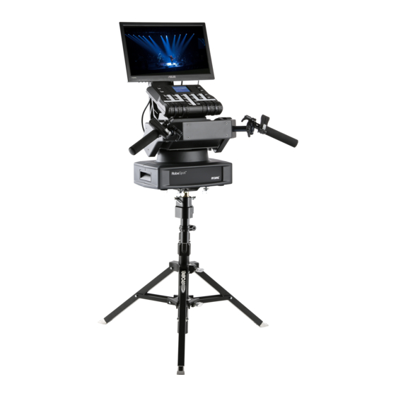
2. Description of the the RoboSpot 2.1 RoboSpot 1 - Monitor installed on the monitor holder 17 - USB (50mA) 2 - FollowSpot Controller 18 - Input for USB lamp (+5V/50mA) 3 - Faders 19 - Adjusting locks for handles 4 - Base 20 - Apertures for 1/4 turn locks 5 - Control handlebars... -
Page 5: Followspot Controller
2.2 FollowSpot Controller 1 - Activation button (actives 13 - Preset button the FollowSpot Controller) 14 - Preset button 2 - BlackOut button 15 - Preset button 3 - Graphic touch screen 16 - Activation button for jog-wheel (25) 4 - Switch On screen button 17 - Preset button 5 - Pan button(enables/disables 18 - Activation button for jog-wheel (26) -
Page 6: Installation
3. Installation The RoboSpot must be installed by a qualified worker in accordance with all national and local electrical and construction codes and regulations. Monitor installation 1. Insert the monitor holder (A) into the slot (B) of the RoboSpot and secure it by means of the lock (C). The lock must be fully screwed and reclined. - Page 7 Tripod and adaptor installation 1. Unfold and adjust height of the tripod and distance of legs (8) by means of adjusting locks (4,5,6,7). The lock (3) has to be in a lower position (as shows arrow on picture below). 2. After inserting the adaptor (1) with spigot (2) to the tripod, the spigot (2) has to be secured by means of the lock (10) and the adaptor (1) by means of the pin (11) which is inserted to the hole (13) of the adaptor (1) as shows arrow on picture below.
-
Page 8: Monitor Shield And Note Holder Installation
3.1 Monitor shield and note holder installation 1. Place the monitor shield (I) on the monitor holder (A) in this way that pins (J) of the monitor shield snap to apertures (K) in the monitor holder and move the monitor shield down until you rich a stop. 2. -
Page 9: Robospot Connection
4. RoboSpot connection After installing the RoboSpot, connect it with the ROBIN BMFL FollowSpot with camera (or the RoboSpot Mo- tionCamera), with another supported ROBIN fixtures and a control desk. The RoboSpot has to be connected with a desk by means of Ethernet cable and fixtures intended for the followspot operation have to be connected by means of DMX cable. - Page 10 In case of using PosiStageNet protocol, you will need to connect an ethernet switch between camera OUT and camera IN of the RoboSpot in order to get position information from the RoboSpot.
-
Page 11: Operation
5. Operation After installing the RoboSpot and connecting it with the ROBIN BMFL FollowSpot (RoboSpot MotionCamera) and another fixtures used for the followspot operation, connect the RoboSpot to mains by means of the en- closed power cord. Press the button ACTIVE (1) in order to activate the FollowSpot Controller. By pressing the button PAN (5) and TILT (6) you can activate/deactivate of the pan/tilt movement of the ROBIN BMFL FollowSpot (and all connected BMFL fixtures to the RoboSpot). - Page 12 Touch the icon on the FollowSpot Controller to display the password entering screen: Enter the password (default password is 5242 and also goes for the 15.6" touch screen ) to enter the main menu of the FollowSpot Controller. The password prevents unauthorized person from changing setting of the FollowSpot Controller.
- Page 13 4.Touch the [cancel] icon and than [back arrow] icon. The screen with effect faders will appear. E.g. Only effects assigned to the jog-wheels will appear on this screen. Effects assigned to the faders will not be shown. Sensitivity of the jog-wheels assigned to the effects can be set at three levels: low, medium and high. The levels of the sensitivity are marked in colour on the screen: low level - red slider medium level - yellow slider...
-
Page 14: Influence Of The Robospot On The Fixture Channels
5.2 Influence of the RoboSpot on the fixture channels The general rule (with a few exceptions described in the table below) is the RoboSpot controls mapped channels (functions) on jog-wheels or faders in range which allows the FollowSpot Controller (see the chapter 6.1 Menu Functions Mapping). - Page 15 The Power/Special Functions channel of supported fixtures offers three control modes of the RoboSpot. You can use a full control of the RoboSpot, fully disable the RoboSpot or disable the RoboSpot excepting two faders and manual pan/tilt. Example for the Robin BMFL FollowSpot: Channel Power/Special Functions (channel 6) DMX values Function...
-
Page 16: Lcd Monitor Screen
5.3 LCD monitor screen The RoboSpot is equipped with the 15.6" (10-point) touch screen with max. resolution 1366 x 768. After switching the RoboSpot and the ROBIN BMFL FollowSpot with camera (or the RoboSpot MotionCamera) on, image scanned by the camera is displayed on the LCD screen. Touch the red cross and move Current scene Touch the edge of the positioning circle... - Page 17 *** To lock the screen, touch the button . The following options will appear on the screen: Lock HUD - this option locks the LCD monitor screen. Positions buttons and pan/tilt movement by means of the control handlebars are available. Lock HUD + Controller - this option locks the LCD monitor screen and the FollowSpot Controller display.
- Page 18 The green lines in the position circle give pan and tilt position of the control handles. The green point in the centre of the position circle signals the middle position of the control handles. If you move with control handles, the distance between the green lines and the red circle will give available range of pan and tilt movement of the control handles.
- Page 19 Sliders menu Zoom slider- use it to change a zoom of currently selected camera. A sensitivity of a camera zoom can be set in three levels: low (green slider), medium (yellow slider) and high (red slider). To change the sensitivity level of the camera zoom, the camera zoom has to be assigned to some jog-wheel of the FollowSpot Controller, please see the chapter "Functions mapping"...
- Page 20 Exposure- the menu item allows you to choose a level (Low, Medium, High) of light intensity in the position circle on the screen to see hidden objects from reason of high light intensity in the position circle on the screen. The item Auto switches the function off.
- Page 21 circle to desired position and press the "+" button. Button no.1 will appear at the bottom of the screen and the button no.1 is assigned to this position of the position circle (if item " Show in scene is active, button no.1 is displayed in the position circle on the screen).
- Page 22 Colour Buttons - the function allows you to change colour on used fixtures together. The function controls colour channels (Red/Green/Blue/White/CTO channels at LEDs fixtures and Cyan/Magenta/Yellow channels at lamp fixtures). When choosing desired colour, corresponding channels are taken over from a desk to the Robospot. Touch the button + and the following screen will appear.
-
Page 23: Streaming A Camera Video
Desired colour can be activated by touching its button in the colour bar. Desk colour button To delete a colour button, touch and hold a finger on the button for a while. The Desk Colour button passes colour channels on to the control from a desk. Multi Dev.Control - the menu serves for activating and setting control of fixtures in the multi device operation. -
Page 24: Saving And Recalling The Followspot Controller Presets
5.5 Saving and recalling the FollowSpot controller presets The FollowSpot Controller offers you to save up to 12 presets. To save the FollowSpot controller preset 1. Press and hold one of the preset buttons (7/9/11/12/13/14/15/17/19/20/21/22) e.g. button (7) until the jog- wheel activating buttons (8/10/16/18) and the pan/tilt buttons (5/6) start to flash. -
Page 25: Robospot Handles Calibration
5.6 RoboSpot handles calibration To calibrate the RoboSpot handles. 1. Install the FollowSpot Controller on the FollowSpot Controller base 1. Deactivate the FollowSpot Controller (button ACTIVE (1) must not light) 2. Move the control handles of the RoboSpot to the calibration position, in this way: pan direction - move handles fully to the left until you reach a stop tilt direction - move handles fully down until you reach a stop 3. -
Page 26: Multi Device Control
5.7 Multi device control The RoboSpot can support more fixtures in the follow spot operation. The fixtures used in the follow spot operation should be placed on a truss around the area intended for the follow spot operation. The fixtures can be placed above stage on one ( two or three) side(s) of the stage or around the stage, placing inside the working area for the follow spot operation is not suitable . - Page 27 Fixtures cannot stay directly on the stage floor. They have to be placed above the stage floor in two positions only: head downwards or head upwards. The plane of fixture´s hanging and the plane of the stage have to be parallel in relation to each other if you use only two position points in the MDC setup.
- Page 28 Important notes for the MDC (Multi Device Control) setup - If you use the Robin BMFL FollowSpot with a camera, do not switch its lamp off and do not close its light output during the MDC setup. - If you use the RoboSpot Motion Camera, set the red positioning circle to the centre of the screen before starting the MDC setup.
- Page 29 There is an example how to create the follow spot operation for three fixtures and two position points. The stage is lighted by the five devices in a row and three of them will be used for the follow spot operation. 1.
- Page 30 Note: In case that setup of DMC has been created, the following message will appear: Select the option "Load" if you want to load existing setup and modified it. Touch the "Next" button. Three fixtures are selected for the multi device operation. Working area for the follow spot operation 3.
- Page 31 Zoom and iris are automatically set to the narrow beam at all devices used in the follow spot operation. Activate one fixture (by touching its button or using arrows), e.g. BMFL FollowSpot, focus it (by means of the FollowSpot Controller) and aim it to the first point on the floor (by means of the RoboSpot handles) as exactly as possible.
- Page 32 6. The following message will appear on the screen: Zoom and iris are automatically set to the narrow beam at all devices used in the follow spot operation. Activate one fixture (by touching its button), e.g. BMFL FollowSpot, focus it (by means of the FollowSpot Con- troller) and aim it to the second point on the floor (by means of the RoboSpot handles) as exactly as possible.
- Page 33 In the following example the fixture 3 does not change its pan value (only tilt value) when head moves from the 1st point to the 2nd point, the 2nd point is not selected correctly. Better position for the 2nd point: 7.
- Page 34 Use the jog-wheels on the FollowSpot Controller (or faders on the screen) to set desired zoom and focus in the point 2 for each fixture. For information: if the option Multi device control is activated, both zoom and focus on all devices are set at 50%.
- Page 35 x,y,z - relative coordinates of the device in relation to the reference device Rx,Ry,Rz - rotation of the device in x, y and z axes SRx, SRy - rotation of the stage towards to reference device Rs - rotation of the stage towards to working space The button "Adj."...
- Page 36 To activate the multi device control, touch the button "On/Off. The icon shows fixtures used in the multi device control If the item "Auto Zoom/Foc." is active, the zoom and focus of fixtures used in the follow spot operation will be carried out automatically (in a range as was adjusted in "1st point" and "2nd point") during moving of the light image on the stage.
- Page 37 Robin DL7S is activated (by touching the button DL7S).
- Page 38 9. When the Multi Device Control is on, select suitable Height Mode. Note: the item Height has to be mapped to some fader or jog-wheel in order to control it during multi device operation. Person mode Stairs mode Setting a height range in a multi device control When you move with a control element (fader or jog-wheel) to which a height is mapped, the height bar with the actual height in % from a stage is displayed on the screen (if the fader or jog-wheel is exactly in the 0% position, the height is not displayed).
- Page 39 To set the height level range, touch and hold your finger on the height bar until the following message will appear. Reset button - resets the height range to 0-100% and calls the test screen Use the he fader or jog-wheel (according to the height mapping) to set minimum height level and touch the Next button.
- Page 40 Examples of height level ranges.
-
Page 41: Intensity Maps
5.8 Intensity maps The RoboSpot allows you to set a light intensity in different points in the area intended for the follow spot operation. The light intensity can be set separately for each fixture used in MDC operation. Setup Before doing Intensity maps, map height and dimmer channels to jog-wheels (not to faders!) Go to the menu "Intensity Maps"... - Page 42 Now set desired light intensity for each fixture (activate fixtures one by one by touching it). E.g. After setting the light intensities, touch the "Next" button. The screen for the second point will appear. Use the RoboSpot´s handles to aim fixtures to desired second position point and touch the "Next" button. The following screen will appear.
- Page 43 Setting the dimmer curve The menu Intensity Maps allows you to select a linear or square law dimmer curve. Selected dimmer curve applies to all fixtures used in MDC setup. When you switching between dimmer curves, the message " Setting dimmer curve for MDC lights to linear" or "...
-
Page 44: Posistage Net
5.9 PosiStage Net The menu option allows you to use a PosiStageNet protocol (an open protocol for on-stage, live 3D position data). Before activating the PosiStageNet protocol, the MDC setup has to be complete. The PosiStageNet protocol is active on both Ethernet connectors (Camera IN/Update, Ethernet ) of the RoboSpot. The item "On/Off"... - Page 45 The item "Set Offset" allows you to set offset of the new origin of coordinates. The values in the field XYZ offset (e.g. -0.038 0 0.189) have to be separated by a space. The item "Show Coord." allows you to display PSN coordinates on the screen. Stage direction SRx(SRy)- virtual inclination of the stage surface in x axis...
- Page 46 3. Aim the beam of reference fixture from point P0 to Point P1. Current coordinates of the point P1 will be dis- played in the PSN Coordinates window. Example: x: 0.038 y: 0.000 z:-0.189 4. Select the option "Set Offset" and type the values from the PSN Coordinates window (with opposite signs) into the field XYZ Offset Values.
-
Page 48: Control Menu
6. Control menu The FollowSpot Controller is equipped with the QVGA Robe touch screen with battery backup which allows you to set the device behaviour according to your needs. Icons used in the touch screen menu. - [back arrow] used to move back to the previous screen (or menu level). -
Page 49: Menu Functions Mapping
6.1 Menu Functions Mapping By entering the menu you can assign effects from the list of available effects to the jog-wheels and faders. List of available effect channels depends of the used moving head. The item All - releases all assigned effects at one go. - Page 50 Fixture Effect Available DMX values Dimmer 0-255 Iris 0-179 Focus 0-255 Zoom 0-255 L Frost 0,1-50 M Frost 0,87-136 H Frost 0,173-222 Color 1 0,130-189 Color 2 0,130-189 Cyan 0-255 Magenta 0-255 Yellow 0-255 0-255 Efw. pos 0-127 Robin BMFL Blade Efw.
- Page 51 Fixture Effect Available DMX values RGW 1 0,32-59 RGWr 1 0-255 FS rot 0-255 FS 1 m 0-255 FS 1 s 0-255 Robin BMFL WashBeam FS 2 m 0-255 FS 2 s 0-255 FS 3 m 0-255 FS 3 s 0-255 FS 4 m 0-255...
- Page 52 Fixture Effect Available DMX values Dimmer 0-255 Iris 0-179 Focus 0-255 Zoom 0-255 Frost 0-179 V Color 0-247 0-255 Green 0-255 Blue 0-255 White 0-255 0-255 Efw. pos 0-127 Efw. rot 0-255 Robin DL4S 0, 32-59 RGW r 0-255 Prism 0-127 Pris r 0-255...
- Page 53 Fixture Effect Available DMX values Color 1 0, 130-189 V Color 0-132 Efw. pos 0-127 Efw. rot 0-255 0, 4-87 RGW 1 0, 32-59 Robin MegaPointe Robin iPointe RGWr 1 0-255 Robin iPointe65 Prism 1 0-27 Pris1 r 0-255 Prism 2 0-27 Pris2 r 0-255...
- Page 54 Fixture Effect Available DMX values Dimmer 0-255 0-255 Green 0-255 Robin Spiider Blue 0-255 Robin iSpiider White 0-255 Robin Tarrantula 0-255 Zoom 0-255 A. Zone 0-72 Fixture Effect Available DMX values Dimmer 0-255 0-255 Green 0-255 Robin LedBeam 150 Robin LedBeam 350 Blue 0-255 White...
- Page 55 Fixture Effect Available DMX values Dimmer 0-255 Iris 0-179 Focus 0-255 Zoom 0-255 L Frost 0, 1-50 M Frost 0, 87-136 H Frost 0,173-222 Color 1 0,130-189 Color 2 0,130-189 Cyan 0-255 Magenta 0-255 Yellow 0-255 0-255 Efw. pos 0-127 Robin Esprite Efw.
- Page 56 Fixture Effect Available DMX values Dimmer 0-255 Focus 0-255 Zoom 0-255 Color 1 0,130-189 Cyan 0-255 Magenta 0-255 Yellow 0-255 0-255 Efw. pos 0-127 Efw. rot 0-127 RGW 1 0,32-59 Robin MMX Blade RGWr 1 0-255 Prism 0-127 Pris r 0-255 Frost 0-179...
- Page 57 Fixture Effect Available DMX values FS 2 s 0-255 FS 3 m 0-255 Robin T2 Profile FS 3 s 0-255 FS 4 m 0-255 FS 4 s 0-255 Fixture Effect Available DMX values Dimmer 0-255 Iris 0-179 Focus 0-255 Zoom 0-255 Frost 0-50, 87-136...
- Page 58 Fixture Effect Available DMX values Dimmer 0-255 Focus 0-255 Frost 0-179 Color 0,130-189 Cyan 0-255 Magenta 0-255 Robin Cuete Yellow 0-255 0,10-89 0,32-59 RGW r 0-255 Prism 0-127 Pris r 0-255 Power 225-239 Fixture Effect Available DMX values Dimmer 0-255 Focus 0-255 Frost...
-
Page 59: Menu Show Library
6.2 Menu Show Library Select/Rename Show - the menu item offers 10 shows. In the show is saved setting of the RoboSpot system: Functions mapping FollowSpot Controller presets Sensitivity of jog-wheels Faders switching and inversion Position buttons DMX addresses and modes of connected devices RDM information about connected devices (only if the option "Manual"... - Page 60 Export Show the menu item allows you to save a show on a USB flash drive connected to the USB port of the RoboSpot. Supported file systems of the USB flash drive are: FAT16, FAT32, EXT2, EXT3, EXT4. To export a show. 1.
- Page 61 3. The list of available show files on the USB flash drive will appear on the LCD screen e.g. 4.Select desired show file (e.g. Show 6.rsl) and touch the button "Load" to import selected show file to the RoboSpot. If the import is successful, the notice: "Import Show OK" will appear. Error and notice messages: "No show files on USB flash drive"...
-
Page 62: Menu All Lamps On/Off
6.3 Menu All Lamps On/Off The menu item allows you to switch on/off lamp in the Robin BMFL FollowSpot and fixtures connected to this Robin BMFL FollowSpot. 6.4 Menu Devices Settings By entering the menu list of available devices will be displayed, e.g. BMFL Follow Spot: 033 (Robin BMFL Follow Spot) RoboCamera: 001 (RoboSpot MotionCamera) Touch desired device and the following menu items will appear. -
Page 63: Menu Dmx In/Out
If you select option the Yes, collision fixtures will be automatically readdressed. If you select No, DMX addresses wil stay without change. 6.6 Menu DMX In/Out After entering the menu item all channels from a current DMX universe are displayed and can be browsed by touching the keys UP/DOWN. -
Page 64: Software Update
IPv4 address has to be set to 10.x.x.x network (for example 10.0.1.10) with netmask 255.0.0.0 . During the update, the FollowSpot Controller has to be attached to the RoboSpot. Do note, that to enable all new features, you must update the RoboSpot base station and also all BMFL fixtures... -
Page 65: Error And Information Messages
1. Connect a computer running ROBE RDM Uploader to the internet and update software libraries (Libraries → Update) 2. Connect the computer and the RoboSpot base station via Ethernet cable. Use the RJ45 socket marked Camera IN/Update on the RoboSpot base station for this connection. -
Page 66: Technical Specifications
9. Technical specifications Supported fixtures: Robin BMFL FollowSpot/Spot/Blade/WashBeam, Robin Pointe, Robin Forte MegaPointe, Robin iPointe, Robin iPointe65, DL4S, DL7S,Robin T1/T2 Profile, Robin MMXWashBeam, Robin MMX Blade, Robin T1 Profile FS, Robin LedBeam 150, Robin Spiider, Robin Tarrantula, Robin Viva CMY, Robin SilverScan, Robin Esprite/Esprite FS, Robin Spote, Robin Cuete, Robin Promotion, Robin iSpiider, Robin LEDBeam 350 Input voltage:... - Page 67 Dimensions with monitor shield and note holder (mm) Weights: 16.5 kg (RoboSpot), 1.9 kg (Monitor Shied + Note Holder), 1.7kg (Adaptor), 8.7 kg (Tripod) Included items 1 x RoboSpot 1 x Adaptor (including spigot) (P/N 99015404) 1 x Tripod for RoboSpot/FollowSpot/LightMaster (P/N 10980350) 1 x Power cable 1 x User manual Optional accessory...
-
Page 68: Maintenance And Cleaning
To preserve the environment please dispose or recycle this product at the end of its life according to the local regulations and codes. Specifications are subject to change without notice. Copyright © 2017-2022 Robe Lighting - All rights reserved January 12, 2022 Made in CZECH REPUBLIC by ROBE LIGHTING s.r.o. Palackeho 416/20 CZ 75701 Valasske Mezirici...
Need help?
Do you have a question about the RoboSpot Base Station and is the answer not in the manual?
Questions and answers
Is there anyway to control pan and tilt parameters from the robospot basestation via ethernet without first connecting dmx?