Table of Contents
Advertisement
Advertisement
Table of Contents

Related Manuals for Robe RoboSpot


Summary of Contents for Robe RoboSpot
- Page 1 Version 2.5...
-
Page 2: Table Of Contents
RoboSpot BaseStation Table of contents 1. Safety instructions ......................3 2. Description of the the RoboSpot ................. 4 2.1 RoboSpot ........................4 2.2 FollowSpot Controller ....................5 3. Installation........................6 3.1 Monitor shield and note holder installation ..............8 4. RoboSpot connection ....................9 5. -
Page 3: Safety Instructions
1. Safety instructions CAUTION! The RoboSpot was designed for indoor use only. The product is for professional use only, it is not for household use. This product has left our premises in absolutely perfect condition. In order to maintain this condition and to ensure a safe operation, it is absolutely necessary for the user to follow the safety instructions and warnings written in this manual. -
Page 4: Description Of The The Robospot
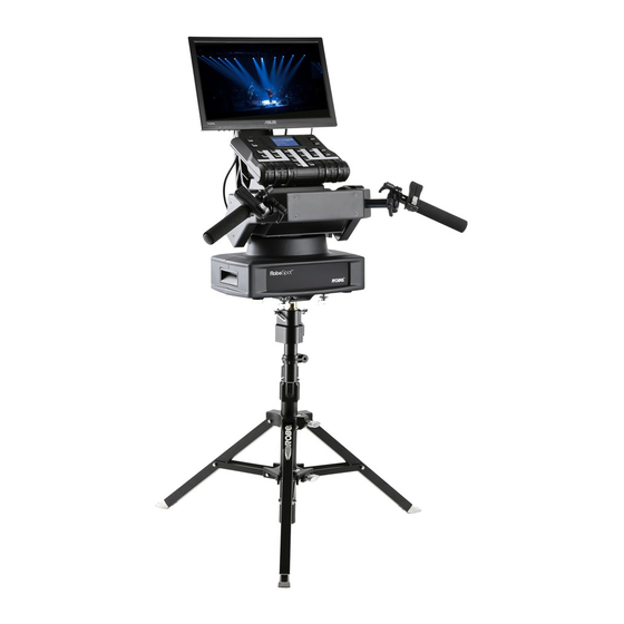
2. Description of the the RoboSpot 2.1 RoboSpot 1 - Monitor installed on the monitor holder 17 - USB (50mA) 2 - FollowSpot Controller 18 - Input for USB lamp (+5V/50mA) 3 - Faders 19 - Adjusting locks for handles... -
Page 5: Followspot Controller
2.2 FollowSpot Controller 1 - Activation button (actives 13 - Preset button the FollowSpot Controller) 14 - Preset button 2 - BlackOut button 15 - Preset button 3 - Graphic touch screen 16 - Activation button for jog-wheel (25) 4 - Switch On screen button 17 - Preset button 5 - Pan button(enables/disables 18 - Activation button for jog-wheel (26) -
Page 6: Installation
Monitor installation 1. Insert the monitor holder (A) into the slot (B) of the RoboSpot and secure it by means of the lock (C). The lock must be fully screwed and reclined. Check the monitor is securely fastened. - Page 7 Position of the pin(11) has to be secured by means of the lock (12). 3. The four quarter -turn locks (9) of the adaptor serve for fastening the RoboSpot on the adaptor. Two workers should install the RoboSpot on the assebled tripod with the adaptor.
-
Page 8: Monitor Shield And Note Holder Installation
3.1 Monitor shield and note holder installation 1. Place the monitor shield (I) on the monitor holder (A) in this way that pins (J) of the monitor shield snap to apertures (K) in the monitor holder and move the monitor shield down until you rich a stop. 2. -
Page 9: Robospot Connection
ROBIN fixtures and a control desk. You do not need to patch the RoboSpot, but fixtures connected to the RoboSpot have to be patched. Note: Fixtures connected to the RoboSpot and not supported by the RoboSpot will be ignored by the RoboSpot. -
Page 10: Operation
It is suitable to set the RoboSpot handlebars to the "middle" position and after that set the pan and tilt position of the moving head by the sliders on the RoboSpot touch screen. - Page 11 Touch the icon on the FollowSpot Controller to display the password entering screen: Enter the password (5242) to enter the main menu of the FollowSpot Controller. The password prevents unau- thorized person from changing setting of the FollowSpot Controller. Enter the menu "Functions Mapping". The list of available effects will appear: If the message"...
- Page 12 Effects assigned to the four jog-wheels and two faders on the handlebars have a priority over DMX values coming from a DMX controller. Functionality of the RoboSpot can by restricted by means of commands on the channel Power/Special Functions (240-255 DMX) of connected fixture.
-
Page 13: Lcd Monitor Screen
5.2 LCD monitor screen The RoboSpot is equipped with the 15.6" (10-point) touch screen with max. resolution 1366 x 768. 1. After switching the RoboSpot and the ROBIN BMFL FollowSpot (or the RoboSpot MotionCamera) on, image scanned by the camera is displayed. - Page 14 Note: the message "Not correct camera settings! Reset camera settings?" informs you that the RoboSpot software and the camera settings are not accordance. Use the option "Yes" to set correct camera settings. The option "Yes" has the same effect as the option "Factory reset " in the Camera button menu.
- Page 15 Note: if you change a camera zoom, you have to move and adjust the position circle on the beam image again. Sliders menu Camera Zoom slider- use it to change a zoom of currently selected camera. A sensitivity of a camera zoom can be set in three levels: low (green slider), medium (yellow slider) and high (red slider).
- Page 16 Blackout Display - use the item to darken the screen. To active the screen, touch it. Network Test - the item runs a connection test between a camera and the RoboSpot. Do not touch any buttons on the FollowSpot controller.
-
Page 17: Streaming A Camera Video
Position Buttons - if the function is on, the "+" button will appear at the bottom of the screen. Move the position circle to desired position and press the "+" button. Button no.1 will appear at the bottom of the screen and the button no.1 is assigned to this position of the position circle (if item "... -
Page 18: Saving And Recalling The Followspot Controller Presets
5.4 Saving and recalling the FollowSpot controller presets The FollowSpot Controller offers to save up to 12 presets. To save the FollowSpot controller preset 1. Press and hold one of the preset buttons (7/9/11/12/13/14/15/17/19/20/21/22) e.g. button (7) until the jog- wheel activating buttons (8/10/16/18) and the pan/tilt buttons (5/6) start to flash. -
Page 19: Robospot Handles Calibration
1. Deactive the FollowSpot Controller (button ACTIVE (1) must not light) 2. Move the control handles of the RoboSpot to the calibration position, in this way: pan direction - move handles fully to the left until you reach a stop tilt direction - move handles fully down until you reach a stop 3. -
Page 20: Multi Device Control
5.6 Multi device control The RoboSpot can support more fixtures in the follow spot operation. The fixtures used in the follow spot operation should be placed on a truss around the area intended for the follow spot operation. The fixtures can be placed above stage on one ( two or three) side(s) of the stage or around the stage, placing inside the working area for the follow spot operation is not suitable . - Page 21 Fixtures cannot stay directly on the stage floor. They have to be placed above the stage floor in two positions only: head downwards or head upwards. Fixture has to be installed on a truss in this way, that its tilt will move in range: >0° and < °90° as shown on the picture below to cover the whole working area for the followspot operation.
- Page 22 There is an example how to create the follow spot operation for three fixtures. The stage is lighted by the five devices in a row and three of them will be used for the follow spot operation. 1. Enter the "Multi Dev. Control" menu on the screen and select the option "Setup MDC". 2.
- Page 23 Select desired reference device from devices intended for the follow spot operation (the reference device should be a device with a camera /BMFL FollowSpot with camera or RoboSpot Motion camera)/ and should not be placed on the edge of fixtures row, optimal position is in the middle of fixtures /if it is possible/, in this case it is the Device 1) and touch the Next button.
- Page 24 Activate the device 1 (by touching desired device button ), focus it (by means of the FollowSpot Controller) and aim it to one point on the floor (by means of the RoboSpot handles) as exactly as possible. Repeat this action for the device 2 and device 3 to aim them to the second point.
- Page 25 Two position points has to be placed on the stage in a way that all fixtures used in the follow spot operation have to change both pan and tilt values when go from the 1st point to the 2nd point. In the following example the fixture 3 does not change its pan value (only tilt value) when head moves from the 1st point to the 2nd point, the 2nd point is not select correctly, better position for the 2nd point is on the picture above.
- Page 26 Note: if the option Multi device control is activated, both zoom and focus on all devices are set at 50%. The values are offsets in relation to the zoom and focus values set at the first and the second point. Touch the Next button.
- Page 27 To activate the multi device control, touch the button "On/Off. Action toolbar If the item "Auto Zoom/Foc." is active (highlighted), the zoom and focus of fixtures used in the follow spot operation will be carried out automatically (in a range as was adjusted in "1st point" and "2nd point") during moving of the light image on the stage.
- Page 28 9. When Multi Device Control is on, select suitable Height Mode. Note: the item Height has to be mapped to some fader or jog-wheel in order to control it during multi device operation. Person mode Stairs mode...
-
Page 29: Control Menu
6. Control menu The FollowSpot Controller is equipped with the QVGA Robe touch screen with battery backup which allows you to set the device behaviour according to your needs. Icons used in the touch screen menu: - [back arrow] used to move back to the previous screen (or menu level). -
Page 30: Functions Mapping
6.1 Functions Mapping By entering the menu you can assign effects from the list of available effects to the jog-wheels and faders. List of available effect channels depends of the used moving head. The item All - releases all assigned effects at one go. - Page 31 Fixture Effect Available DMX values Dimmer 0-255 Iris 0-191 Focus 0-255 Zoom 0-255 L Frost 0,1-50 M Frost 0,87-136 H Frost 0,173-222 Color 1 0,130-189 Color 2 0,130-189 Cyan 0-255 Magenta 0-255 Yellow 0-255 0-255 Efw. pos 0-127 Robin BMFL Blade Efw.
- Page 32 Fixture Effect Available DMX values RGW 1 0,32-59 RGWr 1 0-255 FS rot 0-255 FS 1 m 0-255 FS 1 s 0-255 Robin BMFL WashBeam FS 2 m 0-255 FS 2 s 0-255 FS 3 m 0-255 FS 3 s 0-255 FS 4 m 0-255...
- Page 33 Fixture Effect Available DMX values Dimmer 0-255 Iris 0-179 Focus 0-255 Zoom 0-255 Frost 0-179 V Color 0-247 0-255 Green 0-255 Blue 0-255 White 0-255 0-255 Efw. pos 0-127 Efw. rot 0-255 Robin DL4S 0, 32-59 RGW r 0-255 Prism 0-127 Pris r 0-255...
- Page 34 Fixture Effect Available DMX values Color 0, 130-189 V Color 0-132 Efw. pos 0-127 Efw. rot 0-255 0, 4-87 0, 32-59 Robin MegaPointe RGW r 0-255 Prism 1 0-27 Pris1 r 0-255 Prism 2 0-27 Pris2 r 0-255 Beam 0-19 Beam r 0-255...
-
Page 35: Show Library
USB flash drive connected to the USB port of the RoboSpot. Supported file systems of USB flash drive are: FAT16, FAT32, EXT2, EXT3, EXT4. To export show. 1. Connect a USB flash drive to RoboSpot and select desired show (e.g. show 6) and confirm it. - Page 36 RSShowLibrary-10.rsL. 3 Select desired show file (e.g. RSShowLibrary-10.rsL) and touch the button "Load" to import selected show file to the RoboSpot. If the import is successful, the notice: "Import Show OK" will appear. Error and notice messages: "No show files on USB flash drive" - it means that no show file was found on the USB flash drive.
-
Page 37: All Lamps On/Off
Discovery Config To RoboSpot Base If you confirm it, list of discovered fixtures will be saved and at every switching the RoboSpot on, fixtures from the list will be loaded to the RoboSpot without discovery procedure running at the RoboSpot starting-up. -
Page 38: Settings
The password applies to the FollowSpot Controller as well as the RoboSpot screen and also to all user presets. You cannot have a different password for each user preset. -
Page 39: Software Update
IPv4 address has to be set to 10.x.x.x network (for example 10.0.1.10) with netmask 255.0.0.0 . During the update, the FollowSpot Controller has to be attached to the RoboSpot. Do note, that to enable all new features, you must update the RoboSpot base station and also all BMFL fixtures controlled by the RoboSpot system. -
Page 40: Error And Information Messages
8. Error and information messages Error message message is signalled by the warning icon in the right top corner of the RoboSpot screen: Touch the warning icon to display a message. Touch the screen to hide the message. List of error and information messages:... -
Page 41: Technical Specifications
USB lamp: 2x USB socket +5V/50mA 1 x USB Pan rage: +/- 80° Tilt range: +/- 40° Fastening: via adaptor on tripod Weights: 16.5 kg (RoboSpot), 1.9 kg (Monitor Shied + Note Holder), 1.7kg (Adaptor), 8.7 kg (Tripod) Dimensions (mm) - Page 42 Dimensions with monitor shield and note holder (mm) Included items 1 x RoboSpot 1 x Adaptor (including spigot) (P/N 9901504) 1 x Tripod for RoboSpot/FollowSpot/LightMaster (P/N 10980350) 1 x Power cable 1 x User manual Optional accessory Monitor Shield and Note Holder for RoboSpot BS (P/N 10980409)
-
Page 43: Maintenance And Cleaning
To preserve the environment please dispose or recycle this product at the end of its life according to the local regulations and codes. Specifications are subject to change without notice. Copyright © 2017-2018 Robe Lighting - All rights reserved June 26, 2018 Made in CZECH REPUBLIC by ROBE LIGHTING s.r.o. Palackeho 416/20 CZ 75701 Valasske Mezirici...
Need help?
Do you have a question about the RoboSpot and is the answer not in the manual?
Questions and answers