Table of Contents
Advertisement
Advertisement
Table of Contents

Subscribe to Our Youtube Channel
Related Manuals for Crest Audio Mixing Console HPW


Summary of Contents for Crest Audio Mixing Console HPW
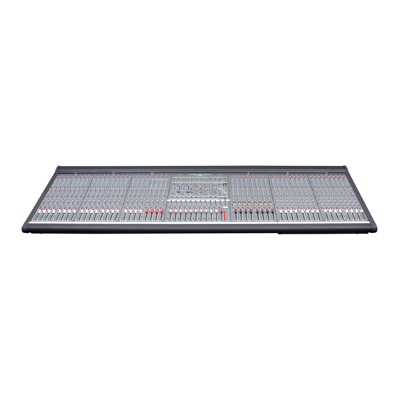
- Page 1 Mixing Console Owner’s Manual...
- Page 3 Owner’s Manual Model Number : Serial Number : opt- external PSU Serial Owner : Purchase Date : Dealer Name : Dealer Number : Install Date : Installed By : Contact Number :...
- Page 4 Intended to alert the user to the presence of uninsulated “dangerous voltage” within the product’s enclosure that may be of sufficient magnitude to constitute a risk of electric shock to persons. Intended to alert the user of the presence of important operating and maintenance (servicing) instructions in the literature accompanying the product.
- Page 5 WARNING: When using electrical products, basic cautions should always be followed, including the following: Read these instructions. Keep these instructions. Heed all warnings. Follow all instructions. Do not use this apparatus near water. Clean only with a dry cloth. Do not block any of the ventilation openings. Install in accordance with manufacturer’s instructions. Do not install near any heat sources such as radiators, heat registers, stoves or other apparatus (including amplifiers) that produce heat.
- Page 6 ACHTUNG: Beim Einsatz von Elektrogeräten müssen u.a. grundlegende Vorsichtsmaßnahmen befolgt werden: Lesen Sie sich diese Anweisungen durch. Bewahren Sie diese Anweisungen auf. Beachten Sie alle Warnungen. Befolgen Sie alle Anweisungen. Setzen Sie dieses Gerät nicht in der Nähe von Wasser ein. Reinigen Sie es nur mit einem trockenen Tuch.
- Page 7 ATTENTION: L’utilisation de tout appareil électrique doit être soumise aux precautions d’usage incluant: Lire ces instructions. Gardez ce manuel pour de futures références. Prétez attention aux messages de précautions de ce manuel. Suivez ces instructions. N’utilisez pas cette unité proche de plans d’eau. N’utilisez qu’un tissu sec pour le nettoyage de votre unité.
- Page 8 CUIDADO: Cuando use productos electrónicos, debe tomar precauciones básicas, incluyendo las siguientes: Lea estas instrucciones. Guarde estas instrucciones. Haga caso de todos los consejos. Siga todas las instrucciones. No usar este aparato cerca del agua. Limpiar solamente con una tela seca. No bloquear ninguna de las salidas de ventilación.
-
Page 10: Table Of Contents
table of contents owner’s manual 1 block diagram p.11 2 mono input p.14 4 stereo inputs p.21 3 automix p.27 5 groups p.28 6 auxes p.33 7 left - right p.35 8 mono output p.37 contents 9 matrix mix p.39 10 master section p.40 11 power supply... - Page 11 +48V POLARITY MIC INPUT Preamp HI PASS LINE INPUT INSERT Pre-Fader Pre EQ DIRECT OUTPUT Pre-fader/Post EQ Dir Out Post EQ Default Mono channels Standard and Automix Line 2 Left Input 1 Gain 1 Right Left Input 2 Right Gain 2 Left Pre-EQ DIRECT OUTPUT Left Post-EQ...
-
Page 12: Hpw Tm
block diagram Mono Mono Left Right GRP 1 Solo L GRP 2 Solo R GRP 3 GRP 4 GROUP 1-8 GRP 5 GRP 6 GRP 7 GRP 8 Aux 1 Mono Mono PRE 1-6 Aux 2 Left Aux 3 Right Aux4 Aux 5 MTX 1... -
Page 13: Block Diagram
GROUP INSERT 1 OF 8 GROUP OUTPUT 1 OF 8 AUX OUTPUT 1-8 AUX INSERT 1-8 LEFT, RIGHT INSERT LEFT, RIGHT OUTPUT Signal/Peak/AFL AUX OUTPUT 9, 10 AUX INSERT 9, 10 MONO INSERT MONO OUTPUT MATRIX OUTPUT 1, 2 ALT OUTPUT 1,2 LEFT RIGHT DIRECT OUTPUT... - Page 14 mono input +48V - +48 volts DC is applied equally (through current-limiting resistors) to both pins 2 and 3 on the mic-input XLR connector. This feature is used with condenser micro- phones and active direct boxes that require an external DC voltage (phantom power) in order to operate.
-
Page 15: Mono Input
EQ features Many audio signals coming into the console require some degree of corrective equaliza- tion in order to be part of a good sounding mix. The input EQ consists of four-bands: high, high-mid, low-mid and low. The high and low bands have fixed frequencies, while the high-mid and low-mid bands are sweepable, with their higher and lower frequencies overlapping adjacent bands. - Page 16 mono input PRE (aux 1–6) - The default signal source for these Aux sends is post-fader. This switch is used for selecting the Pre-fader signal for Auxes 1-6. The normal Pre- fader signal is derived Post-EQ. (See internal jumper options on page 18.) Aux sends are Post-EQ, Post-fader Aux sends are Post-insert, Post-EQ, Pre-fader aux send level 1–10...
-
Page 17: Channel Fader
channel muting features The HPW™ is equipped with an 8-Scene muting system. An input channel can be assigned to any of the 8 available groups (1 thru 8). When a Mute Scene preset (located in the Master module) is active, all channels assigned to that scene are muted. In addition, the local channel mute switch can be used to change the status of the channel indepen- dently of any of the scenes. - Page 18 mono input - options Solder-Blob locations CHAN 7 CHAN 8 CHAN 8 CHAN 7 CHAN 3 CHAN 3 CHAN 5 CHAN 4 CHAN 6 HPW Input EQ PCB HP-Eight Input EQ PCB (Upper PCB) (Upper PCB) CHAN 6 CHAN 5 CHAN 4 HPW Input HP-Eight Input Main PCB...
-
Page 19: User Options
user options There are a number of user options available for the Mono inputs. These are implemented by way of solder-pads on the back-side of the Mono Input circuit boards (upper EQ board of the pair). There are a number of solder-pads avail- able, made up of split-circles of tinned copper. -
Page 20: Rear Panel Features
features overview rear panel features direct out 1/4" TRS jack - jack. The default signal routing is derived Pre-fader/Post-EQ. This can be changed by an internal option to Post-insert/Pre-EQ. The output jack is TRS, impedance-balanced. insert jack - This switching 1/4” TRS jack allows an external signal processor to be inserted into the signal path of the channel. - Page 21 automix The automix option is comprised of a set of eight mono channels that have auto- matic gain-shared mixing capability. The circuitry determines which input is the loud- est and gives it dominance in the mix by reducing the level of other assigned inputs, based on their individual instantaneous levels.
- Page 22 gain 1&2 - These controls adjust the input gains of the two selectable inputs (TRS and RCA). Both Left and Right circuits are simultaneously adjusted. Unity gain is at the mid-point (with a detent), min and max gain adjust is 20dB. The stereo inputs were designed for line-level sources and can accommodate a wide range of input levels.
- Page 23 stereo inputs aux send features Ten aux sends are available for creating individual output mixes from the Stereo Inputs. These mixes can be used for driving effects processors, providing monitor mixes, creating broadcast or alternate sound reinforcement mixes, or other special requirements. When in the default post fader configuration, the signal is an equal sum of the Left and Right ste- reo signals.
-
Page 24: Stereo Inputs
channel muting features mute - Pressing this switch mutes the stereo feed to any of the assigned buses and any Aux sends. The mute is part of the mute scene programmable function and behaves just as the mutes in the mono channels do. mute LED - The associated red-LED illuminates when the stereo channel is muted. - Page 25 stereo input - options owner’s manual Solder-Blob locations CHAN 5 CHAN 8 CHAN 7 CHAN 6 CHAN 5 HPW Input EQ PCB (upper) p. 25...
- Page 26 user options There are a number of user options available for the Stereo inputs. These are implemented by way of solder-pads on the back-side of the Stereo Input circuit boards (upper EQ board of the pair). There are a number of solder-pads avail- able, made up of split-circles of tinned copper.
-
Page 27: Rear Panel Connectors
stereo inputs owner’s manual rear panel connectors The connectors associated with all the Stereo Inputs are located on the rear panel. Line Input 1 has 1/4” TRS jacks, Line Input 2 has unbalanced RCA inputs. The TRS inputs are balanced and can accept either balanced or unbalanced signals. direct out, 1/4"... - Page 28 groups (audio subgroups) features The HPW is equipped with 8 audio subgroups, in addition to the main L/R and Mono mix buses. All of the Inputs (Mono and Stereo) have full assignment capabilities to all 11 of these mix buses. Typically, these 8 groups are used to create sub-mixes within the main program.
-
Page 29: Groups
group monitoring features Within this Group section, the 100mm fader is normally in the Group audio path. This can be changed with the use of the Fader-Reverse switch. When the Fader-Reverse switch is depressed, the corresponding Aux output is controlled by the 100mm fader (the Group output is then controlled by the corresponding Aux rotary pot). - Page 30 groups fader-reverse function using the HPW as a monitor console Because of its 10 Aux sends, the HPW can be used as a 10-output Monitor mixer. Each input channel can access all of the individual Aux mixes, allowing 10 unique mixes to be generated.
- Page 31 group mixing features After using the groups to create the desired sub-mixes, you typically want to route and combine them with other signals or groups to create various output mixes. These mixes can be your final house mix (L/R/Mono), a spe- cial mix for a choir or vestibule area, or an additional feed tailored specifi- cally for a video or TV broadcast.
- Page 32 groups group connectors- rear panel The HPW group output connections are located on the Master rear output panel. Each group features a 1/4” TRS output connector, along with a 1/4” TRS Insert connector. The output is a ground-compensated, impedance-balanced TRS jack. For wiring purposes, treat this connector exactly like a balanced output.
-
Page 33: Auxes
auxes (auxiliary mixes) Ten Aux buses are available for creating individual output mixes from the Input chan- nels of the Console. These mixes can be used for driving effects processors, provid- ing monitor mixes, creating broadcast or alternate sound reinforcement mixes, or other special requirements. - Page 34 auxes aux connectors-rear panel The HPW Aux output connections are located on the Master rear output panel. All of the auxiliary outputs are fully balanced with auxes 1-8 featuring XLR connectors and auxes 9 and 10 having 1/4” TRS connectors. All 10 auxes also have TRS inserts. The TRS Insert jack is wired as Tip=Send, Ring=Return, Sleeve= Audio Ground.
-
Page 35: Left - Right
left and right (main audio buses) features The HPW is equipped with 3 main audio buses in addition to the 8 audio subgroups. This section of the manual deals with 2 of those 3 main buses - Left and Right, and the Mono bus will be described later. - Page 36 left - right fader-reverse function using the HPW as a monitor console Because of its 10 Aux sends, the HPW can be used as a 10-output Monitor mixer. Each input channel can access all of the individual Aux mixes, allowing 10 unique mixes to be generated.
-
Page 37: Mono Output
mono (main audio bus) features The HPW is equipped with 3 main audio buses in addition to the 8 audio subgroups. This section of the manual deals with 1 of those 3 main buses - the Mono bus. The Mono bus is directly assignable from all of the Mono and Stereo Inputs, the 8 audio subgroups and the L-R main buses. - Page 38 left - right, mono output L/R and mono connectors- rear panel The HPW Mono output connections are located on the Master rear output panel. The output features a male XLR output connector, along with a 1/4” TRS Insert con- nector. The output is a servo balanced XLR jack. The TRS Insert jack is wired as Tip=Send, Ring=Return, Sleeve= Audio Ground.
-
Page 39: Matrix Mix
matrix mix The HPW features a 2-output Matrix section. Each Matrix can consist of a mixture of any of the 11 main mix buses: the 8 audio subgroups, Left, Right, and Mono. Each of these main buses feed the 2 matrix buses through individual Matrix Send pots, all located within the Master module, above the fader of the associated bus. -
Page 40: Master Section
¡ master section stereo returns features The HPW has 2 stereo returns located within the Master module. These inputs are designed to accept line level balanced signals (from an effects unit, a CD player, or other line level source) on their 1/4” TRS balanced jacks. gain This control adjusts the gain of the input amplifiers. - Page 41 EQ features Many audio signals coming into the console require some degree of corrective equal- ization in order to be part of a good sounding mix. Each stereo input is equipped with a fixed-frequency, three-band EQ. The HF and LF bands have a shelving response.
-
Page 42: Stereo Fader
master section ¡ channel muting features MUTE and MUTE LED Pressing this switch will mute the stereo feed to any of the assigned buses and any Aux sends. The associated red-LED will illuminate when the stereo channel is muted. bus assignment features The bus assignment section offers considerable flexibility for creating what eventu- ally becomes the main output mix. - Page 43 master section ¡ signal monitoring features The stereo inputs are equipped with a bicolor LED that displays the summed, Pre- fader signal level with varying intensity green illumination, and also indicates impend- ing channel overload (within 3dB of clipping) by turning red. Clipping is sensed both pre and post fader, so even if the fader is down, you will be informed of any preamp or EQ related overload problems.
- Page 44 ¡ master section alternate outputs features The HPW has 2 alternate outputs located within the Master module. These outputs are designed to allow the user to select the signal source that is being output. This feature is especailly useful when sending audio for broadcast, recording, an attached room, public spaces or assisted hearing devices.
- Page 45 master This knob controls the main level of the alternate output. PK/Sig LED The After-Fader signal is shown as varying GREEN intensity, while the channel clip warning illuminates RED. When this switch is depressed, the stereo after-fader signal is sent to the monitoring system.
- Page 46 ¡ master section ambience inputs features The HPW has been designed with a stereo mic ambience input for “real life” sound enhancement. This feature allows sound from the room to be added to the sound system allowing better reflection of what the audience hears. The ambience input has direct out- puts and can be assigned to the auxes or alternate outputs.
- Page 47 aux send level 5-8 These knobs adjust the amount of signal sent to the corresponding AUX buses. Unity gain occurs at the zero setting, with 6dB additional gain available above that. Note: The Aux Sends default to buses 5-8. To send to auxes 1-4 internal solder blob jumbers are avail- able.
-
Page 48: Monitor Section
master section ¡ owner’s manual master section: monitoring and control overview The HPW is equipped with versatile monitoring, talkback, and muting sections that allow the operator to monitor and control the various signals within the console. A brief overview of each is presented. Each section will be described on its own, fol- lowing a brief overview. - Page 49 master section: monitoring and control monitor section The dedicated Monitor Section allows the user to listen to and view the various sig- nals operating within the Console. This section consists of the monitor select circuitry and dual LED meters, the Solo system, and headphones.
- Page 50 ¡ master section monitor output 1/4" TRS jack (rear panel) The monitor output signal is available on these output jacks. The jacks are impedance-balanced and ground-compensated. Tip is +Drive, Ring is -Drive Return, Sleeve is Chassis Ground Send (Drive) impedance is 50Ω Ring impedance is 50Ω...
- Page 51 headphone source The operator can use the headphones to listen to the various signals within the Console. The headphones are normally fed from whatever sources are selected in the Monitor Section. The level is controlled by the Phone Level control (the Monitor level control will not affect the headphone level).
-
Page 52: Talkback Section
master section ¡ talkback section The operator can use the built-in facilities of the HPW to talk to the main, group, or aux buses in the console. Often times, the operator will need to selectively commu- nicate with a performer, or slate a performance during a recording. talkback input This front-panel XLR jack can accept mic-level signals and is equipped with a phan- tom power option header (internally located behind the XLR jack within the Master... - Page 53 power supply - internal internal supply The HPW is equipped with an internal power supply, based on a universal input, switch-mode design. As such, you can power the HPW from any worldwide AC mains voltage from 100 to 240 volts, 50 or 60Hz. Input power is approx 200 watts maximum (56-chan console), so power requirements are minimal.
-
Page 54: Power Supply
power supply external power supply - front NOTE: The 2U rack-mount panel can be removed from the chassis if a stand-alone, floor or desktop supply is preferred. Remove the six #8 screws securing the front panel to the chassis. Remove the front panel and store it away, then replace the #8 screws (to fill the threaded holes in the front of the chassis). - Page 55 power supply external power supply The style and pinout of the DC Connectors on the HPW are the same as the Crest X-Series of consoles (X-Eight, X-Four, X-VCA, X-Monitor), and the existing X-Series supply CAN be used to power the HPW console. The voltage requirements are the same, but the current demands are less with the HPW.
-
Page 56: External Power Supply
5 DGND NO USER SERVICABLE PARTS INSIDE. REFER 6 +48V @1A SERVICING TO QUALIFIED SERVICE PERSONNEL EXTERNAL DC INPUT 7 -18V @3A Crest Audio Inc. FROM BACKUP SUPPLY Fair Lawn, NJ 07410 USA CONNECT ONLY TO www.crestaudio.com APPROVED CREST SUPPLY HP-Eight owner’s manual... - Page 57 power supply power supply - dual powering the HPW There are 4 distinct ways to power the HPW: 1) Internal Supply ONLY 2) Internal Supply PLUS an External Supply as a Redundant Supply 3) Internal Supply PLUS an External Supply as a Back-Up Supply 4) External Supply ONLY # 1 is the default powering method.
-
Page 58: Specifications
£ specifications Frequency Response THD+Noise Noise Crosstalk Phase Shift XLR Inputs Main Outputs Insert Points Internal Power Supply Ext DC Power Requirements (Max for 56-chan model) Dimensions: HPW 20+4 Weight: HPW 20+4 Dimensions: HPW 28+4 Weight: HPW 28+4 Dimensions: HPW 36+4 Weight: HPW 36+4 Dimensions: HPW 44+4 Weight: HPW 44+4... - Page 60 http://www.crestaudio.com HPW Owner's Manual Version 1.0 05/31/06...
Need help?
Do you have a question about the Mixing Console HPW and is the answer not in the manual?
Questions and answers