Table of Contents
Advertisement
Advertisement
Table of Contents

Related Manuals for Crest Audio X-RACK XR-20


Summary of Contents for Crest Audio X-RACK XR-20
- Page 1 owner’s manual X-Rack rack mount mixers XR-20 XR-24...
- Page 3 Opening the unit will expose you to detailed in documentation. potentially dangerous voltages. There are For replacement packaging, call Crest Audio’s no user serviceable parts inside. This symbol is used to warn opera- Customer Service Department directly.
- Page 4 Duration Per Day In Hours Sound Level dBA, Slow Response 1 1/2 1/4 or less...
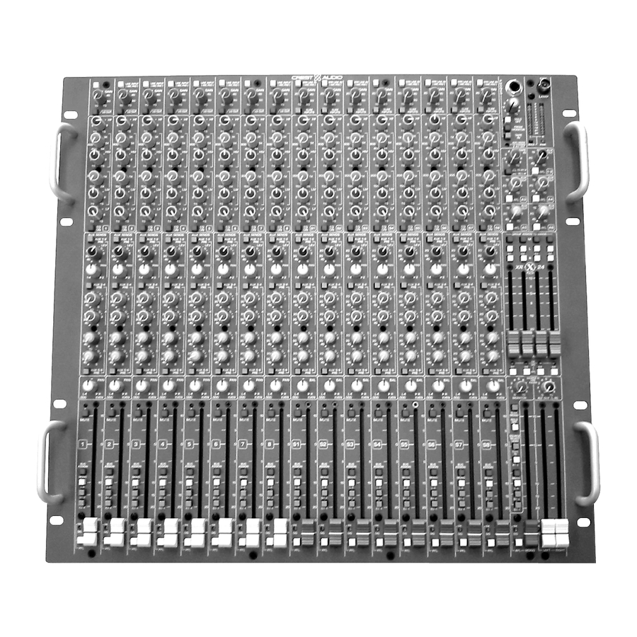
- Page 5 Front panel controls and rear panel connections Thank you and congratulations on your purchase of your new Crest Audio X-Rack mixer. We’re confident that you will enjoy many years of trouble-free service from it. You will quickly find Stereo Input channels p.17...
- Page 6 XR-20/24 block diagram XR-20 / XR-24 owner’s manual p. 4...
- Page 7 The intention is to make the manual easy to read while including all the technical details needed for getting the most out of the X-Rack - a compact, flexi- ble, feature-rich addition to Crest Audio's growing line of audio mixing console products. conventions Control Icons This manual uses symbols to illustrate what the control descriptions are referring to.
- Page 8 Mono input channel XR-20 / XR-24 owner’s manual Module Controls Block diagram +48V ON +48V GAIN BAL MIC IN 70Hz 12 - 70 dB -18dB/Oct LINE BAL LINE IN INPUT 27dB PREAMP p. 6...
-
Page 9: Front Panel Features
Mono Input channel Front panel features Mono Input channel features are identical for both the XR-20 and the XR-24. The XR-20 has 12 Mono inputs and the XR-24 has 8 Mono inputs. Line Input (mic pad) The input preamp circuit is set up to accept a mic-level signal. This signal is brought in via the XLR mic-input connector located on the rear panel. - Page 10 Mono input channel XR-20 / XR-24 owner’s manual Module Controls Block diagram LEVEL FREQ LEVEL FREQ LEVEL LEVEL EQ ON LOW MID HI MID 80 HZ 80 - 2 KHZ 400 - 8 KHZ 12 KHZ FOUR BAND EQ p. 8...
- Page 11 Mono Input channel Front panel features Many audio signals coming into the console require some degree of corrective eq in order to be part of a good sounding mix. XR-20 & XR-24 offer a very useful and great sounding eq section on each channel. The input EQ consists of four bands: High, High-mid, Low-mid and Low.
- Page 12 Mono input channel XR-20 / XR-24 owner’s manual Module Controls Block diagram MUTE MONO G1-2 G3-4 EQ ON CHAN FADER FADER AMP 12 KHZ BUS ASSIGN SWITCHES 100MM LEVEL A1-2 SOURCE MUTE ? FADER A3-4 LEV 3 PRE-SOURCE BUFFER LEV 4 LEV 5 A5-6 INSERT...
- Page 13 Mono Input channel AUX send features Six auxiliary sends are available for creating individual output mixes. These can be used to drive effects processors, provide monitor mixes, create broadcast or alternate sound reinforcement mixes, or for other special requirements. Note: The default PRE setting for the Auxes is pre-fader, but post-mute, post-insert, and post eq.
- Page 14 Mono input channel XR-20 / XR-24 owner’s manual Module Controls Block diagram SOLO LEFT SOLO RIGHT PEAK CIRCUIT SOLO DC MUTE MONO G1-2 G3-4 EQ ON CHAN FADER FADER AMP BUS ASSIGN SWITCHES 100MM LEVEL A1-2 SOURCE MUTE ? FADER LEV 3 A3-4 PRE-SOURCE...
- Page 15 Mono Input channel Bus assignment features The bus assignment section offers considerable flexibility for creating what even- tually becomes the main output mix. Two stereo subgroups are available for creat- ing submixes or separate stereo mixes. All assignments are derived post-fader, post-eq, and post-mute.
-
Page 16: Rear Panel
Mono input channel XR-20 / XR-24 owner’s manual Connectors Rear panel Block diagram GAIN BAL MIC IN 70Hz 12 - 70 dB -18dB/Oct LINE BAL LINE IN INPUT 27dB PREAMP INSERT SEND / RTN DIRECT OUT SOURCE POST FADER DIRECT OUT FADER REAR PANEL X-RACK MONO INPUT MODULE... - Page 17 Mono Input channel Rear panel features 48 V Phantom power 48 volts DC is applied to pins 2 and 3 on the mic-input XLR connector. This option is used with condenser microphones and active direct boxes that require an external DC voltage (phantom power ) in order to operate. Line INPUT jack Line-level signals, balanced or unbalanced, may be brought into the input channel through this jack.
- Page 18 Stereo input channel XR-20 / XR-24 owner’s manual Controls Module Block diagram +48V ON +48V GAIN BAL MIC IN MONO LINE 15 - 60 dB LEFT BAL LINE IN 27dB BAL MIC IN RIGHT INPUT SIGNAL BAL LINE IN INPUT 27dB PEAK PREAMP...
- Page 19 Stereo Input channel Front panel features Stereo Input channels features are identical for both the XR-20 and the XR-24. The XR- 20 has 4 Stereo inputs, and the XR-24 has and 8 Stereo inputs. On both models the Stereo inputs are located to the left of the master section, to the right of the Mono inputs.
- Page 20 Stereo input channel XR-20 / XR-24 owner’s manual Controls Module Block diagram FADER LEVEL FREQ LEVEL FREQ LEVEL LEVEL MUTE EQ ON LOW MID HI MID CHAN 80 HZ 80 - 2 KHZ 400 - 8 KHZ 12 KHZ FADER FOUR BAND EQ - LEFT LOW MID HI MID...
- Page 21 Stereo Input channel Front panel features Stereo EQ The Stereo Input channel has two parallel EQ circuits that are controlled by the same set of knobs. high frequency—HF Boost / Cut 15dB boost and cut. Shelving @ 12 kHz high mid—HM Frequency Continuously sweepable between 400 Hz and 8 kHz.
- Page 22 Stereo input channel XR-20 / XR-24 owner’s manual Controls Module Block diagram SOLO LEFT SOLO RIGHT FADER PEAK MUTE CIRCUIT SOLO DC MONO G1-2 G3-4 FADER AMPS CHAN FADER LEFT BUS ASSIGN POST SWITCHES FADER RIGHT 100MM A1-2 LEVEL LEFT RIGHT A3-4 LEV 3...
- Page 23 Stereo Input channel AUX send features Six auxiliary sends are available for creating individual output mixes. These can be used to drive effects processors, provide monitor mixes, create broadcast or alternate sound reinforcement mixes, or for other special requirements. Note: The default PRE setting for the Auxes is pre-fader, but post-mute, post-insert, and post eq.
- Page 24 Stereo input channel XR-20 / XR-24 owner’s manual Controls Module SOLO LEFT SOLO RIGHT FADER PEAK MUTE CIRCUIT SOLO DC MONO G1-2 G3-4 FADER AMPS CHAN FADER LEFT BUS ASSIGN POST SWITCHES FADER RIGHT 100MM A1-2 LEVEL LEFT RIGHT A3-4 LEV 3 SOURCE MUTE ?
- Page 25 Stereo Input channel Bus assignment features The bus assignment section offers considerable flexibility for creating what even- tually becomes the main output mix. Two stereo subgroups are available for creat- ing submixes or separate stereo mixes. When the channel is being used as a stereo input, Left/Right, Groups 1 &...
- Page 26 Stereo input channel XR-20 / XR-24 owner’s manual Connectors Rear panel Block diagram GAIN BAL MIC IN LEVEL FREQ LEVEL MONO LINE 15 - 60 dB LOW MID LEFT 80 HZ 80 - 2 KHZ FOUR BAND BAL LINE IN 27dB LOW MID 80 HZ...
- Page 27 Stereo Input channel Rear panel features 48 V Phantom power 48 volts DC is applied to pins 2 and 3 on the mic-input XLR connectors. This option is used with condenser microphones and active direct boxes that require an external DC voltage (phantom power ) in order to operate. Line INPUT jacks - Left and Right Line-level signals, balanced or unbalanced, may be brought into the input channel through this jack.
- Page 28 Master section XR-20 / XR-24 owner’s manual Module Controls Block diagram METERS FOLLOW SOLO, NORMALLY SHOW LEFT OUT L / R OUT RIGHT OUT LEFT LEVEL PRE-FADER SOLO FEED MONO L - R RIGHT SOLO CTRL PRE-FADER SOLO AUDIO SOURCES FOR MONITOR - ALL PRE-FADER PHO NES MONITOR MO N-L...
- Page 29 Master section Front panel features The XR-20 & XR-24 have a comprehensive output section, including meters, master level controls, and a flexable group assignment section. Headphone control section In normal use, the headphone out is used to monitor the Solo system. The Solo system is made up of anything that is PFL’d (pre-fader-listen) or AFL’s (after fader listen).
- Page 30 Master section XR-20 / XR-24 owner’s manual Controls Module Block diagram METERS FOLLOW SOLO, NORMALLY SHOW LEFT OUT L / R OUT RIGHT OUT LEFT LEVEL PRE-FADER SOLO FEED MONO L - R RIGHT SOLO CTRL PRE-FADER SOLO AUDIO SOURCES FOR MONITOR - ALL PRE-FADER PHO NES MONITOR MO N-L...
- Page 31 Master section Front panel features FROM MONITOR The post-level control MONITOR output becomes the signal in the head- phones when nothing is soloed. This overrides TAPE IN if the TAPE IN button is depressed. TAPE IN The TAPE IN signals appear in the headphones when the FROM MONITOR button is not depressed and nothing is Soloed.
- Page 32 Master section XR-20 / XR-24 owner’s manual Controls Module Block diagram TAPE TO TAPE-IN AUX 1-2 LEVEL LEFT BUS TAPE-IN L RIGHT BUS TAPE IN TAPE TO PHONES TAPE-IN R & MONITOR TAPE IN MONO (RECESSED) LEFT OUT TAPE-IN L X-RACK AUX BUSES 1-2 (STEREO PAIR) AUX 1...
- Page 33 Master section Front panel features TAPE IN level On the rear panel there are Left and Right TAPE IN connectors, both 1/4” TRS and RCA. They can be used to bring in a stereo source such as a two-track playback from tape, CD, MD, or a sampler. This knob controls the level to the Aux 1/2 and Left/Right buses.
- Page 34 Master section XR-20 / XR-24 owner’s manual Controls Module Block diagram X-RACK GROUPS INSERT GROUP (1 OF 4 SHOWN) SEND / RTN MIX AMP FADER MONO LEFT RIGHT GROUP GROUP TO GROUP FADER BUS IN MIX-AMP POST GROUP-TO-MAIN FADER ASSIGN SWITCHES GROUP GROUP...
- Page 35 Master section Front panel features GROUP assignment section The XR-20 offers a flexible group assignment arrangement. Each of the four Groups can be assigned to Left, Right and Mono busses, in any combination. M - Mono assignments for Groups 1, 2, 3 & 4 Each of the four groups has a Mono assignment button for routing its post-fader signal to the Mono mix bus.
- Page 36 Master section XR-20 / XR-24 owner’s manual Controls Module Block diagram AUDIO SOURCES FOR MONITOR - ALL PRE-FADER PHONES MONITOR MON-L GRP3-4 GRP1-2 L - R MONO AUX1-2 TAPE IN SOLO OFF LEVEL MONO MON-R MONITOR SOURCE SELECT ( SELECTED SOURCES ADD TOGETHER ) MONITOR SOLO FEED L - R...
- Page 37 Master section Front panel features MONITOR Output section The XR-20 and XR-24 offer an extensive monitoring system which can be used for several alternate mix and remote listening purposes. The main L/R & M mixes, the Groups, Auxes 1&2, the Tape IN, and the Solo system can all be routed to the Monitor outs.
- Page 38 Master section XR-20 / XR-24 owner’s manual Controls Module Block diagram AUDIO SOURCES FOR MONITOR - ALL PRE-FADER PHONES MONITOR MON-L GRP3-4 GRP1-2 L - R MONO AUX1-2 TAPE IN SOLO OFF LEVEL MONO MON-R MONITOR SOURCE SELECT ( SELECTED SOURCES ADD TOGETHER ) MONITOR SOLO FEED L - R...
- Page 39 Master section Front panel features MONITOR Output section SOURCE SELECT The Source select portion of the Monitor system allows you do assign the prima- ry mix buses to the Monitor outputs. All assignments are post insert, pre-fader. All selected sources are added (summed) together. TAPE IN Assigns the TAPE IN L &...
- Page 40 Master section XR-20 / XR-24 owner’s manual Controls Module Block diagram X-RACK MAIN OUT L-INSERT LEFT-RIGHT LEFT SEND / RTN MIX AMP L-PRE FADER LEFT MIC LEVEL L / R FADER LEFT SIGNAL L-POST BAL OUT FADER 30dB PEAK 100MM RIGHT R-INSERT SEND / RTN...
- Page 41 Master section Front panel features Mono PK/SIG LED Green/Red - Flashes to indicate the Mono master level. Green during nor- mal operation and red to indicate overload either at the mix amp or at the fader. Left/Right PK/SIG LED Green/Red - Flashes to indicate the summed Left/Right master levels. Green during normal operation and red to indicate overload either at the mix amps or at the faders.
- Page 42 Master section XR-20 / XR-24 owner’s manual Connectors Rear panel Block diagram X-RACK MAIN OUT L-INSERT LEFT LEFT-RIGHT SEND / RTN MIX AMP L-PRE LEFT FADER MIC LEVEL L / R FADER LEFT SIGNAL L-POST BAL OUT FADER 30dB PEAK 100MM R-INSERT RIGHT...
- Page 43 Master section Rear panel features Left, Right and Mono bus inputs These three female XLR’s are used to bring external signals directly into the Left, Right and Mono mix buses. This is useful for linking multiple mixers together. Group 1, 2, 3 & 4 bus inputs These 1/4”...
- Page 44 Master section XR-20 / XR-24 owner’s manual Rear panel Block diagram X-RACK GROUPS INSERT GROUP (1 OF 4 SHOWN) SEND / RTN MIX AMP FADER MONO LEFT RIGHT GROUP GROUP TO GROUP BUS IN FADER MIX-AMP POST GROUP-TO-MAIN FADER ASSIGN SWITCHES GROUP GROUP...
- Page 45 Master section Rear panel features AUX Inserts 1 through 6 The Aux masters have pre-fader inserts for patching in signal proces- sors. This is useful when using Aux outputs for stage monitors. Tip is Send and Ring is Return. Aux OUT TRS Jacks 1 through 6 The six post-fader Aux master outputs are available at these 1/4”...
- Page 46 Master section XR-20 / XR-24 owner’s manual Use 5-Pin DIN cable to SOLO-LINK: interconnect two Consoles TIES SOLO AUDIO AND CONTROL BETWEEN SOLO LINK CONSOLES. SLAVE SOLOS SHOW UP ON MASTER CONSOLE. BNC CONNECTOR FOR 12VOLT LAMP SOLO-LINK CONNECTORS. ( ON FRONT PANEL ) USE 5-PIN DIN CABLE FROM POLY SLAVE CONSOLE OUT...
- Page 47 Master section Rear panel features Solo Link When using multiple X-Rack mixers together, the solo systems can be linked. A 5-pin DIN cable is used to link the Solo Audio and control signals. AC Input The XR-20 and XR-24 use an internal switching power supply which is capable of accepting a wide range of line voltages.
- Page 48 p. 46...
-
Page 49: Specifications
Specifications Specifications Frequency response +0/-1dB 20Hz-20kHz ref 1kHz (any input to any output) any output <0.01% THD 20Hz-20kHz@ +15dBu out Noise mic ein: better than –128dBu 20Hz to 20kHz 150 ohm source, 60dB gain Bus Noise: better than -85dBu Crosstalk channel mute >90dB, channel routing >80dB channel fader attenuation >90dB aux send attenuation >85dB... - Page 50 Crest Audio 100 Eisenhower Drive Paramus NJ 07652 Crest P/N D7000025 XR-20 / XR-24 owner’s manual (201) 909-8700 Version 1.0 March 28, 20001 www.crestaudio.com...
Need help?
Do you have a question about the X-RACK XR-20 and is the answer not in the manual?
Questions and answers