Table of Contents
Advertisement
Advertisement
Table of Contents

Related Manuals for Crest Audio X-RACK XRM


Summary of Contents for Crest Audio X-RACK XRM
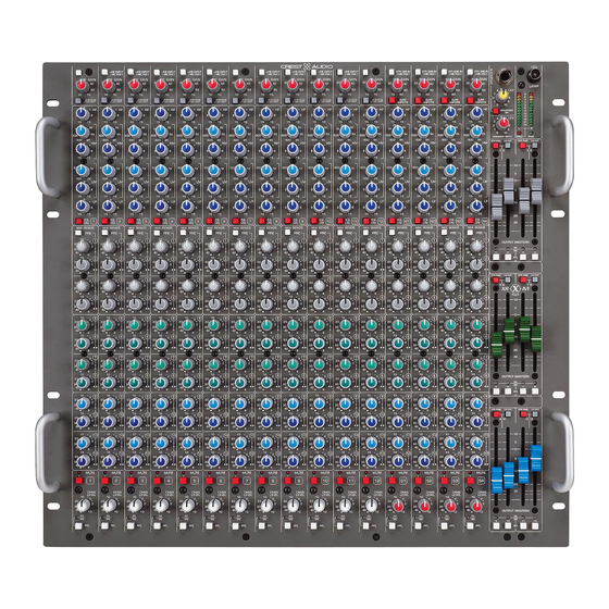
- Page 1 owner’s manual X-Rack rack mount mixers XRM - 12 Output Monitor Mixer...
-
Page 2: Important Precautions
Opening the unit will expose you to detailed in documentation. potentially dangerous voltages.There are For replacement packaging, call Crest Audio’ s no user serviceable parts inside. This symbol is used to warn opera- Customer Service Department directly. - Page 3 If you have any operating concerns that are not cov- ered in this manual, or have application questions of any type, don’t hesitate to contact Crest Audio directly either by phone, fax, or email. Here is our technical support contact information:...
- Page 4 XRM block diagram XRM owner’s manual...
-
Page 5: How To Use This Manual
X-Rack - a compact, flexi- ble, feature-rich addition to Crest Audio's growing line of audio mixing console products. conventions Control Icons This manual uses symbols to illustrate what the control descriptions are referring to.This... - Page 6 Mono input channel XRM owner’s manual Module Controls LINE INPUT ( MIC PAD ) GAIN GAIN LO CUT – LO CUT – – – Block diagram MIX SENDS +48V ON – • – BAL XLR • – • – GAIN LINE 70Hz 10 - 70 dB...
-
Page 7: Front Panel Features
Mono Input channel Front panel features Line Input (Mic Pad) With this switch in the UP position, the input preamp circuit is set up to accept a mic-level signal. This signal is brought in via the XLR mic-input connector located on the rear panel.The 1/4"... -
Page 8: Block Diagram
Mono input channel XRM owner’s manual Module Controls LO CUT GAIN – LO CUT – – – – – MIX SENDS – • – – • – • – – • – • – • – MIX SENDS • – •... - Page 9 Mono Input channel Front panel features Equalizer (EQ) Many audio signals coming into the console require some degree of corrective eq in order to be part of a good sounding mix. XRM offers a 4-Band EQ on each channel.The input EQ consists of the bands: High, High-Mid, Low-Mid and Low.The High and Low frequency bands are shelving equalizers, each have a boost/cut control and their frequencies are fixed.The High-Mid and Low- Mid bands have a bell-shaped response, each band features variable boost/cut and adjustable fre-...
- Page 10 Mono input channel XRM owner’s manual Module Chan Fader Chan Sends Master Faders COMMON INPUT SOLO STR PAIR LO CUT STR PAIR LO CUT MIX SENDS 1 – 2 3 – 4 • GAIN – – LO CUT – • •...
- Page 11 Mono Input channel Front panel features Mix Send features The XRM is capable of generating 12 mono mixes, 6 stereo mixes, or a combination of both mono and stereo mixes. Each of the six Odd/Even pairs of sends can be configured as a stereo pair- the Odd pot becomes the level control, the Even pot becomes the pan pot.The changeover to stereo operation is controlled by the STR PAIR switches located above the master faders.A LO CUT switch is also present for activating the hi-pass filter (40Hz, -18dB/oct) for each pair of...
- Page 12 Mono input channel XRM owner’s manual Module Controls • MUTE GAIN LO CUT – CHAN LE VEL – – • – – Block diagram MIX SENDS – SOLO LEFT MAIN RIBBON SOLO RIGHT • CABLE – PEAK 40 WAY CIRCUIT •...
- Page 13 Mono Input channel Front panel features Channel Level and Control This next set of controls allows the operator to control and monitor the overall level of the channel signal. Mute Sw and LED The Mute switch kills the channel signal and prevents it from feeding any Mix Send pots.The mute- element itself is a FET transistor, allowing for timed, ramped on-off control of the channel signal.This avoids any “pops and clicks”...
-
Page 14: Rear Panel
Mono input channel XRM owner’s manual Connectors Rear panel +48V +48V +48V +48V +48V +48V +48V +48V +48V +48V +48V +48V +48V +48V +48V +48V Balanced Line Inputs +48V For Stereo Channels S1–S4 PUSH PUSH PUSH PUSH Balanced Line In Balanced Line In Balanced Line In Balanced Line In... -
Page 15: Rear Panel Features
Mono Input channel Rear panel features +48 V On +48 volts DC is applied equally (thru current-limiting resistors) to both pins 2 and 3 on the mic- input XLR connector.This feature is used with condenser microphones and active direct boxes that require an external DC voltage (phantom power) in order to operate. - Page 16 Mono input channel XRM owner’s manual Connectors Rear panel +48V +48V +48V +48V +48V +48V +48V +48V +48V +48V +48V +48V +48V +48V +48V +48V Balanced Line Inputs +48V For Stereo Channels S1–S4 PUSH PUSH PUSH PUSH Balanced Line In Balanced Line In Balanced Line In Balanced Line In...
- Page 17 Mono Input channel Rear panel features (continued): Split-Out XLR jack This male XLR jack is wired pin-to-pin to the female XLR input jack. In combination with the female XLR, it forms a passive,Y-Split of the input signal.This split-signal can be used to feed the mic input to another mixer (usually the FOH mixer), or to “mult”...
- Page 18 Stereo input channel XRM owner’s manual Controls Module STR LINE IN ( MIC PAD ) GAIN STR LINE IN ( MIC PAD ) GAIN INPUTS – – INPUTS – Block diagram – +48V ON XRM STEREO INPUT MOD ON S1 4 STEREO INPUTS AVAILABL MIX SENDS –...
- Page 19 Stereo Input channel Front panel features The XRM features four, full-function Stereo Input channels.These inputs are labeled S1 thru S4 and are located directly left of the master section. Each stereo channel features two mic preamps, so mic-level stereo sources can be processed on one common channel.
- Page 20 Stereo input channel XRM owner’s manual Controls Module STR LINE IN ( MIC PAD ) GAIN INPUTS – INPUTS – – – – – ON S1 MIX SENDS – • – – • – • – – • – • –...
- Page 21 Stereo Input channel Front panel features Stereo EQ The Stereo Input channel has two parallel EQ circuits that are controlled by the same set of knobs. It is functionally identical to the Mono Input EQ. Many audio signals coming into the console require some degree of corrective eq in order to be part of a good sounding mix.
- Page 22 Stereo input channel XRM owner’s manual Module Master Faders Chan Level Chan Sends STR PAIR LO CUT STR PAIR LO CUT ON S1 STR LINE IN ( MIC PAD ) 1 – 2 3 – 4 MIX SENDS GAIN • –...
- Page 23 Stereo Input channel Mix Send features The XRM is capable of generating 12 mono mixes, 6 stereo mixes, or a combination of both mono and stereo mixes. Each of the six Odd/Even pairs of sends can be configured as a stereo pair- the Odd pot becomes the level control, the Even pot becomes the pan pot.The changeover to stereo operation is controlled by the STR PAIR switches located above the master faders.A LO CUT switch is also present for activating the hi-pass filter (40Hz, -18dB/oct) for each pair of mixes.
- Page 24 Stereo input channel XRM owner’s manual Controls Module • MUTE STR LINE IN ( MIC PAD ) GAIN INPUTS CHAN – LE VEL – – • – Block diagram – ON S1 XRM STEREO INPUT MODULE SOLO LEFT MIX SENDS 4 STEREO INPUTS AVAILABLE SOLO RIGHT FADER...
- Page 25 Stereo Input channel Front panel features Channel Level and Control This next set of controls allows the operator to control and monitor the overall level of the channel signal. Both sides of the Stereo channel (left & right) are simultaneously controlled. Mute Sw and LED The Mute switch kills the channel signals and prevents it from feeding any Mix Send pots.The mute- element itself is a FET transistor, allowing for timed, ramped on-off control of the channel signal.This...
- Page 26 Stereo input channel XRM owner’s manual Connectors Rear panel +48V +48V +48V +48V +48V +48V +48V +48V +48V +48V +48V +48V +48V +48V +48V +48V +48V Balanced Line Inputs For Stereo Channels S1–S4 PUSH PUSH PUSH PUSH Balanced Line In Balanced Line In Balanced Line In Balanced Line In...
- Page 27 Stereo Input channel Rear panel features +48 V On +48 volts DC is applied equally (thru current-limiting resistors) to both pins 2 and 3 on both the L & R mic-input XLR connectors.This feature is used with condenser microphones and active direct boxes that require an external DC voltage (phantom power) in order to operate.
- Page 28 Master section XRM owner’s manual Module Controls 12 V LAMP SPEAKERS LAMP LE V COMMON INPUT SOLO STR PAIR LO CUT STR PAIR LO CUT 1–2 3–4 SPEAKERS LE V COMMON INPUT SOLO STR PA R O CUT STR PA R O CUT OUTPUT MASTERS Block diagram...
-
Page 29: Master Section
Master section Front panel features The XRM master section contains the controls and indicators for the Solo system, headphone and Monitor system, and Mix Master outputs.This section allows the operator to control the overall operation of the mixer. A BNC lamp connector, supplied with +12 volts, is also located within this section. Each individual sub-system will be described in detail. - Page 30 Master section XRM owner’s manual Block diagram- Common Input Module COMMON INPUT CIRCUITRY LAMP COMMON MIX BUSES LE V INPUT - L COMMON INPUT LEVEL SPEAKERS LE V COMMON INPUT - R COMMON INPUT SOLO EVEN MIX BUSES STR PAIR LO CUT STR PAIR LO CUT...
- Page 31 Master section Front panel features (continued) Common Input Often, a click track, tape playback or ref track, needs to be heard by all the performers.An input chan- nel can be used for this, with all mix sends turned up to the same level. If an input channel is not avail- able, the Common Input section can be used for that purpose.
- Page 32 Master section XRM owner’s manual Controls Module COMMON INPUT SOLO STR PAIR LO CUT STR PAIR LO CUT LAMP 1 – 2 3 – 4 SPEAKERS COMMON INPUT SOLO STR PAIR LO CUT STR PAIR LO CUT 1–2 3–4 OUTPUT MASTERS OUTPUT MASTERS STR PAIR LO CUT...
- Page 33 Master section Front panel features (continued) Master Fader - Mix Output Level Each of the twelve mixes has its own 60mm master fader.This fader controls the main output of the mix and allows the operator to easily adjust the level sent to the perform- ers.
- Page 34 Master section XRM owner’s manual Bus Inputs Mix Inserts and Outputs Mix Insert Mix Insert Mix Insert Mix Insert Mix Insert Mix Insert Bus Input to Mixes Mix Out Mix Out Mix Out Mix Out Mix Out Mix Out Block diagram XRM MIX PAIR ODD MIX MAIN...
- Page 35 Master section Rear panel features Main Outputs 1 thru 12 The XRM has 12 Mix outputs. Each output features the following connectors: Bus Input Mix Insert Main Out Bus Input Each of the 12 mixes has an associated Bus Input jack.This female XLR allows external signals to be mixed into the XRM, either from another X-Rack mixer, or any other audio source.
- Page 36 Master section XRM owner’s manual Rear panel Common Input to All Mixes ( Level Control on Front Panel ) Left Right (Odd) (Even) Monitor Controlled SPEAKER-ON Left Right Switch (Odd) (Even) Block diagram SOLO AND MONITOR CIRCUITS SOLO MIX AMPS METERS SOLO LEFT FOLLOW SOLO...
- Page 37 Master section Rear panel features (continued) Other Inputs and Outputs Common Input A stereo input is provided for feeding a common signal to all of the 12 mix buses simultane- ously. From the stereo source, the left signal will feed all of the odd mixes, the right signal will feed all of the even mixes.
- Page 38 Information and warnings SOLO X-RA CK LINK RACK-MOUNT MIXER Professional Audio Products Designed and Built in the USA Crest Audio Inc. Fair Lawn, NJ 07410 USA Use 5-Pin DIN cable to interconnect www.crestaudio.com SOLO Systems of X-Rack Mixers AC IN CAUTION...
- Page 39 Master section Rear panel features (continued) Solo Link When using multiple X-Rack mixers together, the solo systems can be linked.This Solo Link is compatible with the XR-20 and XR-24 Rack mixers. A 5-pin, shielded DIN cable, wired pin-to- pin, can be used to link the Solo Audio and control signals between mixers.The “Slave” mixer has its own solo’d signals appear in its own solo system, but these signals are also passed to the “Master”...
- Page 40 Ω I/O Connections • Operating Levels • Impedance ( – 60dBu Bal In (Mic) 1= CHS + 4dBu Bal In (Line) 2= IN + + 4dBu Bus In 3= IN – Common In + 4dBu • XLR Female • 1= CHS Split Out Passive 2= OUT +...
-
Page 41: Specifications
Specifications Specifications Frequency response +0/-0.5dB 20Hz-20kHz ref 1kHz (any input to any output) THD+noise any output <0.01% THD 20Hz-20kHz@ +15dBu out Noise mic ein: better than –128dBu 20Hz to 20kHz 150 ohm source, 60dB gain Bus Noise: better than -85dBu Crosstalk/Shutoff All Crosstalk measurements: 20Hz to 20kHz BW Channel Mute >90dB... - Page 42 Crest Audio 16-00 Pollitt Drive Fair Lawn NJ 07410 Crest P/N D7000028 XRM owner’s manual (201) 475-4600 Version 1.01 May 28, 2002 www.crestaudio.com...
Need help?
Do you have a question about the X-RACK XRM and is the answer not in the manual?
Questions and answers
how is the xrm connected to an alesis hd24?