Advertisement
Available languages
Available languages
Quick Links
PRO LOOP C
D
Bedienungsanleitung
Ringschleifenverstärker
PRO LOOP C
GB
Operating Instructions
Loop amplifier
PRO LOOP C
F
Mode d'emploi
Amplificateur à boucle magnétique
PRO LOOP C
NL
Gebruiksaanwijzing
Ringlusversterker
PRO LOOP C
Seite 2
Page 10
Page 18
Pagina 26
Advertisement

Related Manuals for AudioSource PRO LOOP C


Summary of Contents for AudioSource PRO LOOP C
- Page 1 PRO LOOP C Seite 2 Bedienungsanleitung Ringschleifenverstärker PRO LOOP C Page 10 Operating Instructions Loop amplifier PRO LOOP C Page 18 Mode d’emploi Amplificateur à boucle magnétique PRO LOOP C Pagina 26 Gebruiksaanwijzing Ringlusversterker PRO LOOP C...
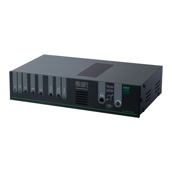
- Page 2 1. Übersicht der Anschlüsse und Bedienelemente PRO LOOP C 1.1 Frontseite Anzeige Eingangssignal Anzeige Ringschleife Regler zum Einstellen der jeweiligen Eingangs-Empfindlichkeit Treble = Höhenregler Regler zum Einstellen des Schleifenstroms Anzeige Spannungsversorgung Kopfhörerausgang Lautstärkeregelung für Kopfhörerausgang 1.2 Rückseite Netzanschluss 230 V / 50 Hz Schraubklemmen für den Anschluss der Ringschleife...
- Page 3 Wir beglückwünschen Sie zum Erwerb Ihres Ringschleifenverstärkers PRO LOOP C. Mit dieser Wahl haben Sie sich für ein Produkt entschieden, welches ansprechendes Design und technische Leistungsstärke gekonnt vereint. Dieses Handbuch beinhaltet die genaue Funktion und Anwendung des Verstärkers. Bitte lesen Sie die Bedienungsanleitung aufmerksam durch, bevor Sie den Verstär- ker einsetzen.
-
Page 4: Wichtige Hinweise
• Geben Sie das Gerät in jedem Fall zur Reparatur nur in eine Fachwerkstatt. 3. Einsatzmöglichkeiten Der PRO LOOP C Verstärker wurde für den Einsatz in professionellen Bereichen ausgelegt, in denen hohe Beständigkeit und sicherer Betrieb unabdingbar sind. Der 100 % kurzschlussfeste Verstärker mit programmierbaren, symmetrischen XLR-Eingängen und sehr stabiler Ausgangs- leistung erfüllt diese Anforderungen. - Page 5 3.2 Leistungsmerkmale des Ringschleifenverstärkers PRO LOOP C • Für Flächen bis 170 m • Ausgangsstrom 11 A RMS • Kurzschlussfest • Automatisch rücksetzbare Sicherung • 2 programmierbare, symmetrische XLR Eingänge und 1 Cinch Line IN Eingang • Line IN oder Mikrofon IN mit Phantomspannung können für Line IN 1 und 2 separat einge- stellt werden •...
- Page 6 4.1 Kabelquerschnitt Anhand der Geometrie des Raumes, können Sie den erforderlichen Kabelquerschnitt mit Hilfe der folgenden Tabelle ermitteln. Kabelquerschnitt in mm Für Fläche 70-150 m 150-800 m > 800 m 4.2 Anschluss der Induktionsschleife Schließen Sie die Kabelenden der Schleife an die Klemmen (10) auf der Rückseite des Verstärkers an.
- Page 7 Wollen Sie die Standardeinstellung ändern, ziehen Sie zuerst das Netzkabel aus der Steckdose und entfernen Sie erst danach den Gehäusedeckel und konfigurieren das Gerät nach folgender Anleitung: K5K6 K1 K2 Abb. Jumper-Positionen Jumper/ Funktion Offen Geschlossen Auslieferungs- Brücke zustand K1 / K2 Phantomspannung IN1* Empfindlichkeit IN1 Mikrofon...
- Page 8 6.1 Erstmalige Inbetriebnahme Bevor Sie das Gerät einschalten, drehen Sie bitte alle Regler auf Linksanschlag. Beachten Sie, dass der Verstärker keinen Ein / Aus Schalter hat, sondern sofort eingeschaltet ist, wenn das Netzkabel an die Steckdose angeschlossen wurde. Schließen Sie nun das beiliegende Netzkabel an. Die Anzeige für die Spannungsversorgung (6) leuchtet jetzt.
- Page 9 Material-Recycling hilft, den Verbrauch von Rohstoffen zu verringern. Weitere Informationen über das Recycling dieses Produkts erhalten Sie von Ihrer Gemeinde, den kommunalen Entsorgungsbetrieben oder dem Geschäft, in welchem Sie das Produkt gekauft haben. 9. Technische Daten PRO LOOP C Eingang Anschlüsse...
- Page 10 1. Overview of the connections and operating elements PRO LOOP C 1.1 Front Input signal indicator Loop indicator Regulator to set the corresponding input sensitivity Treble Regulator to set the loop power Power supply indicator Earphone jack Volume control for the earphone jack 1.2 Rear...
- Page 11 We would like to congratulate you on the purchase of your PRO LOOP C loop amplifier. You have chosen a product that skillfully combines appealing design with high technical performance. This handbook describes exactly how the amplifier works and how it is to be used.
- Page 12 3. Applications The PRO LOOP C amplifier was designed for use in professional venues where high reliability and safe operation are essential. The 100 % short-circuit-proof amplifier with programmable, symmetrical XLR inputs and extremely stable output power meets these requirements. The AGC function attenuates the signal level of such constant signals as oscillation and sine cur- ves to - 10 dB, thus providing for consistent field strength and stable sound.
- Page 13 3.2 PRO LOOP C loop amplifier performance features • For areas up to 170 m • 11 A RMS output power • Short-circuit-proof • Automatic reset for the fuse • 2 programmable, symmetrical XLR inputs and 1 cinch Line IN input •...
- Page 14 4.1 Cable cross section On the basis of the geometry of the room, you can calculate the cable cross section required with the help of the following table. Cable cross section in mm For area measuring 70-150 m 150-800 m >...
- Page 15 If you want to alter the standard setting, first pull the plug out of the wall outlet and then remove the device cover and configure the device according to the following directions: K5K6 K1 K2 Fig. Jumper positions Jumper Function Open Closed Default...
- Page 16 6.1 First-time operation Before you switch on the device, please turn all the control knobs as far to the left as possible. Please note that the amplifier does not have an on/off switch and will switch on as soon as the power cord is plugged into the wall outlet.
- Page 17 Material recycling helps to reduce the consumption of raw materi- al. You will receive further information on the recycling of this product from your local com- munity, your communal disposal company or your local dealer. 9. PRO LOOP C specifications Input Connections...
- Page 18 1. Synoptique des raccords et des éléments de commande PRO LOOP C 1.1 Face avant Témoin du signal d'entrée Témoin de la boucle magnétique Vis de réglage de la sensibilité de chaque entrée Treble = réglage des aigus Vis de réglage du courant de boucle Témoin d'alimentation du secteur...
- Page 19 Félicitations pour l'achat de cet amplificateur à boucle magnétique PRO LOOP C qui allie parfaitement design plaisant et performance technique. Ce manuel décrit le fonctionnement exact et le mode d'emploi de l'amplificateur. Merci de lire ce mode d’emploi avec attention avant d'utiliser l'amplificateur.
- Page 20 3. Applications L'amplificateur PRO LOOP C a été conçu pour une utilisation professionnelle imposant fiabilité et sûreté de fonctionnement. Cet amplificateur 100 % résistant aux courts-circuits avec des entrées XLR symétriques programmables et une puissance de sortie très stable répond à ces critères.
- Page 21 3.2 Caractéristiques techniques de l'amplificateur à boucle magnétique PRO LOOP C • Pour surfaces jusqu'à 170 m • Courant de sortie 11 A RMS • Résistant aux courts-circuits • Fusible automatique • 2 entrées XLR symétriques programmables et 1 entrée Cinch Line IN •...
- Page 22 4.1 Section du câble A partir de la surface de la pièce, on peut déterminer la section de câble nécessaire à l'aide du tableau suivant. Section du câble en mm Pour une surface de 70-150 m 150-800 m > 800 m 4.2 Raccordement de la boucle inductive Raccorder les extrémités de câbles de la boucle aux bornes (10) situées au dos de l'appareil.
- Page 23 Pour modifier ce paramétrage, débrancher tout d'abord le câble de raccordement de la prise puis retirer le couvercle du boîtier avant de configurer l'appareil ainsi : K5K6 K1 K2 Fig. Positions des cavaliers Cavalier/ Fonction Ouvert Fermé Réglage en pont sortie d’usine K1 / K2 Tension fantôme IN1*...
- Page 24 6.1 Première mise en service Avant de mettre l'appareil en service, tourner toutes les vis de réglage jusqu'en butée mini- male (rotation antihoraire). Attention, l'amplificateur n'est pas muni d'un interrupteur marche- arrêt mais est activé dès que le câble de raccordement est branché. Raccorder ensuite le câble de raccordement fourni.
- Page 25 Pour en savoir plus sur le recyclage de ce produit, veuillez contacter les autorités locales compétentes, votre mairie ou le magasin où vous avez effectué votre achat. 9. Caractéristiques techniques du PRO LOOP C Entrée Raccordements 2 fiches XLR symétriques...
- Page 26 1. Overzicht van de aansluitingen en bedieningselementen PRO LOOP C 1.1 Voorkant Indicator ingangssignaal Indicator ringlus Regelaar voor het instellen van de ingangsgevoeligheid Treble = regelaar hoge tonen Regelaar voor het instellen van de lusstroom Indicator spanningstoevoer Hoofdtelefoonuitgang Volumeregeling voor hoofdtelefoonuitgang 1.2 Achterkant...
- Page 27 Hartelijk gefeliciteerd met de aankoop van uw Ringlusversterker PRO LOOP C. U hebt een product gekozen dat aantrekkelijk design optimaal combineert met overtuigende technische prestaties. Dit handboek beschrijft de werking en het gebruik van de versterker. Lees deze handleiding zorgvuldig door voor u de versterker gebruikt. Wij behouden ons bovendien het recht voor wijzigingen aan te brengen in het kader van de productontwik- keling.
- Page 28 • Laat het apparaat alleen repareren door een vakbedrijf. 3. Gebruiksmogelijkheden De PRO LOOP C -versterker werd ontwikkeld voor professioneel gebruik, dat een stabiele en betrouwbare werking vereist. De 100 % kortsluitingsbestendige versterker met programmeer- bare, symmetrische XLR-ingangen en zeer stabiel uitgangsvermogen voldoet aan deze eisen.
- Page 29 3.2 Kenmerken van de ringlusversterker PRO LOOP C • Voor oppervlakken tot 170 m • Uitgangsstroom 11 A RMS • Kortsluitingsbestendig • Zekering met automatische reset • 2 programmeerbare, symmetrische XLR-ingangen en 1 cinch Line IN-ingang • Line IN of Microfoon IN met fantoomspanning kunnen voor Line IN 1 en 2 afzonderlijk ingesteld worden •...
- Page 30 4.1 Kabeldoorsnede Aan de hand van de geometrie van de kamer kunt u de vereiste kabeldoorsnede bepalen met behulp van de volgende tabel. Kabeldoorsnede in mm Voor oppervlakte 70-150 m 150-800 m > 800 m 4.2 Inductielus aansluiten Sluit de kabeluiteinden van de lus aan op de klemmen (10) aan de achterkant van de versterker.
- Page 31 Om de standaardinstelling te wijzigen, trekt u eerst het netsnoer uit het stopcontact. Pas daarna verwijdert u het deksel van de behuizing en configureert u het apparaat volgens de onderstaande instructies: K5K6 K1 K2 Fig. jumper-posities Jumper/ Functie Open Gesloten Toestand bij Brug levering...
- Page 32 6.1 Eerste inbedrijfstelling Voor u het apparaat inschakelt, draait u alle regelaars tot tegen de aanslag naar links. Bedenk dat de versterker geen aan/uit-schakelaar heeft maar onmiddellijk ingeschakeld is zodra het netsnoer wordt aangesloten op het stopcontact. Sluit nu het meegeleverd netsnoer aan. De indicator voor de spanningsvoeding (6) brandt nu.
- Page 33 Materiaalrecyclage helpt het verbruik van grondstoffen te reduceren. Meer informatie over de recyclage van dit product krijgt u bij uw gemeente, de communale afval- verwijderingsbedrijven of in de zaak waar u dit product heeft gekocht. 9. Technische gegevens PRO LOOP C Ingang Aansluitingen...
- Page 36 RM424600 · 1107...
Need help?
Do you have a question about the PRO LOOP C and is the answer not in the manual?
Questions and answers