Advertisement
Quick Links
Advertisement

Related Manuals for Bosch PHANTOM EDGE


Summary of Contents for Bosch PHANTOM EDGE
- Page 1 Installation Manual PHANTOM EDGE Discover the World of AIoT...
-
Page 2: Table Of Contents
Table of Contents Sl No. Content Pg No. List of components Phantom Edge overview Installation steps Technical specification Safety instructions for installation Uninstallation and End-of-Life disposal instructions Regulatory Information... -
Page 3: List Of Components
List of components Quantity Sl No. It Phantom Edge Sensor Device LTE Antennas Wi-Fi Antenna Current Transformer (CT) with Connector set of 3 CT Cable Extender (Optional) Voltage Connection Cable with Connector Cable Ties Mounting Screws Contact and Warranty Card... -
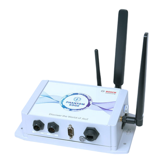
Page 4: Phantom Edge Overview
Phantom EDGE View 2.1 Front View VOLTAGE INPUT CT INPUT Voltage CT Input RS 232 Ethernet Input Indicator 2.2 Right View LTE 1 Micro Differential Antenna 1 Sim Slot Pressure Element... - Page 5 2.3 Left View Hardware ID Technical Specifications & Manufacturer Details Label 2.4 Back View LTE 2 Wi-Fi Wi-Fi Antenna 2 Antenna...
-
Page 6: Installation Steps
If Wi-Fi connection is not available, use SIM card for it LTE 1 Gently pull the flap on its right side to reveal the Micro SIM card slot LTE 1 Insert Micro SIM into Phantom Edge as per the marking sticker... - Page 7 LTE 1 Close the Micro SIM cap and fasten it firmly without any bulge...
- Page 8 3.2 Mounting Identify a flat painted wall or metallic surface to mount Phantom Edge. Ensure that Phantom Edge is mounted within 1 meter of radius from the point of CT installation. Phantom Edge can be mounted in the following options:...
- Page 9 Option B: Mount Phantom Edge on a vertical surface using screws Use the Drill Paper Guide and mark Drill holes of sufficient depth to the four locations to drill on the accommodate wall plugs provided in target wall the installation kit...
- Page 10 3.3 Antenna Connection LTE 1 Insert LTE antenna 1 into LTE antenna 1 port and rotate the antenna nut in a clockwise direction until it is firm. Ensure not to overtighten. LTE 2 Wi-Fi Insert LTE antenna 2 into LTE antenna 2 port and rotate the antenna nut in a clockwise direction until it is firm.
- Page 11 LTE 2 Wi-Fi Insert Wi-Fi antenna into Wi-Fi antenna port and rotate antenna nut in a clockwise direction until it is firm. Ensure not to overtighten. 3.4 CT Connection Line 1 Line 2 Line 3 Identify each CT by line 1, 2 & 3 label behind the CT...
- Page 12 CT and line label, is oriented in the direction of power source. Ensure color code of the power cable and line label matches. (Refer Exhibit 1) VOLTAGE INPUT CT INPUT Connect the CT female connector to the male connector on Phantom Edge, which is labelled as Current Input...
- Page 13 Connect the female connector of insulation from wires. Connect the this cable to the male connector on four-individual wire strands in the Phantom Edge, which is labelled as voltage connector cable to the Voltage Input appropriate points of the four-pole MCB.
- Page 14 Use this option only If you need to collect the data from a device using RS232 port RS232 Identify RS232 female connector connected to machine PLC VOLTAGE INPUT CT INPUT Connect machine PLC RS232 female connector to the male connector of Phantom Edge and tighten the screws...
- Page 15 Identify the recommended Amphenol RJ45 Cable RCP-5SAMMM-SLM7Bxx male connector connected to machine PLC VOLTAGE INPUT CT INPUT RS232 Connection Connect machine’s RJ45 ethernet male connector to the RJ45 female port of Phantom Edge and rotate connector nut in a clockwise direction to tighten it...
- Page 16 3.8 Tidy Up PHANTOM EDGE Discover the World of AIoT Voltage Connection Ethernet Connection Tidy Up RS232 Connection Use the cable ties to secure and bundle the cables PHANTOM EDGE Discover the World of AIoT Voltage Connection Ethernet Connection Tidy Up RS232 Connection Fill in the contact details of local technician and tag it on the voltage cable.
- Page 17 3.9 Connection Diagram Load Source 4 Pole MCB PHANTOM EDGE Discover the World of AIoT CT Connection Ethernet Connection RS232 Connection Voltage Connection Exhibit 1 Color code used with Green or Black Yellow Blue components in the kit Region Neutral (N) Line 1 (L1) Line 2 (L2) Line 3 (L3)
-
Page 18: Technical Specification
115 kbps) Upto 7 days of data backup, in case of connectivity loss Phantom Edge device is rated for 0.1% accuracy, but overall accuracy is limited due to CT’s 1% accuracy In case of delta connection, reach out to manufacturer... - Page 19 Customized to US, General Features Color Code EU and APAC regions Device Mounting Wall Mount or Flat Surface Mount Weight ~ 0.876 kg Dimensions (mm) 220.8 X 156.7 X 62.5 (L X B X H) Considered for Phantom Edge device only...
-
Page 20: Safety Instructions For Installation
Do not drop Phantom Edge. It may lead to its damage or malfunctioning. If the phantom edge unit is used in a manner not specified by the manufacturer, the protection provided by the equipment may be impaired. Service & Support... -
Page 21: Uninstallation And End-Of-Life Disposal Instructions
Be sure your hands are dry and wear non-conductive gloves, protective clothing, andshoes with insulated soles Turn off the electrical supply before disconnecting Phantom Edge from LT panel Make sure, LT panel is de-energized, by using a tester. When an electric tester touches a live or hot wire, the bulb inside the tester lights up showing that the respective wire is live. -
Page 22: Regulatory Information
FCC Regulatory Conformance: FCC Compliance Notification to User: Phantom Edge device comply with Part 15 of the FCC Rules. Operation is subject to the following two conditions: (1) these devices may not cause harmful interference, and (2) these devices must accept any interference received, including interference that may cause undesired operation. - Page 23 © Robert Bosch Engineering and Business Solutions Private Limited (RBEI). All rights reserved, also regarding any disposal exploitation, reproduction, editing, distribution, as well as in event of the Robert Bosch Engineering and Business Solutions PVT. LTD. India | Europe | USA | Japan | UK | Middle East | China | Vietnam | Mexico...
Need help?
Do you have a question about the PHANTOM EDGE and is the answer not in the manual?
Questions and answers