Advertisement
Quick Links
Advertisement

Related Manuals for Bosch PHANTOM EDGE


Summary of Contents for Bosch PHANTOM EDGE
- Page 1 PHANTOM EDGE Discover the World of IoT...
-
Page 2: Table Of Contents
Table of Contents Sl No. Content Pg No. List of components Phantom Edge overview Installation steps Technical specification Safety instructions Uninstallation and End-of-Life disposal instructions... -
Page 3: List Of Components
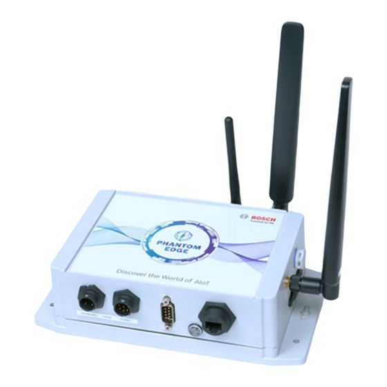
Current Transformer (CT) with Connector set of 3 CT Cable Extender (Optional) Voltage Connection Cable with Connector Cable Ties Mounting Screws Contact and Warranty Card Drill Paper Guide PHANTOM EDGE PHANTOM EDGE Asset Name/No: Asset Location: Facility Contact: Phone Number: www.boschphantom.com... - Page 4 PHANTOM EDGE View 2.1 Front View 2.2 Right View LTE 1 VOLTAGE INPUT CT INPUT MICRO SIM Voltage CT Input RS-232 Ethernet Micro Differential Input Indicator Antenna 1 Sim Slot Pressure Element 2.3 Left View 2.4 Back View CAUTION RBSGS18121RI1V1R...
-
Page 5: Installation Steps
MICRO SIM Gently pull the flap on its right side to reveal the Micro SIM card slot LTE 1 MICRO SIM Insert Micro SIM into Phantom Edge as per the marking sticker LTE 1 MICRO SIM Close the Micro SIM cap... - Page 6 3.2 Mounting Identify the location to mount Phantom Edge. Ensure that Phantom Edge is mounted within 1 meter of radius from the point of CT installation. Phantom Edge can be mounted in the following options: Option A: Mount Phantom Edge in a horizontal direction using stickers...
- Page 7 3.3 Antenna Connection LTE 1 MICRO SIM Insert LTE antenna 1 into LTE antenna 1 port and rotate the antenna nut in a clockwise direction until it is firm. Ensure not to overtighten. LTE 2 Wi-Fi Insert LTE antenna 2 into LTE antenna 2 port and rotate the antenna nut in a clockwise direction until it is firm.
- Page 8 Identify each CT by line 1, 2 Clamp CT around the connector to the male & 3 label behind the CT individual power cable for each connector on Phantom Edge, phase. Ensure that the front which is labelled as Current surface of the CT and Input line label, is oriented in the direction of power source.
- Page 9 Connect machine PLC RS232 female connector to the connected to machine PLC male connector of Phantom Edge and tighten the screws 3.7 Ethernet Connection (Optional) Use this option only If need to collect the data from a device using ethernet port...
- Page 10 3.8 Tidy Up PHANTOM EDGE Voltage Connection Ethernet Connection Tidy Up RS232 Connection Use the cable ties to secure and bundle the cables PHANTOM EDGE Voltage Connection Ethernet Connection Tidy Up RS232 Connection Fill in the contact details of local technician and tag it on the voltage cable. Ensure all details are correctly filled for emergency response.
- Page 11 Phantom device installation Connection Diagram Load Source 4 Pole MCB PHANTOM EDGE CT Connection Ethernet Connection RS232 Connection Voltage Connection Exhibit 1 Color code used with Green or Black Yellow Blue components in the kit Region Neutral (N) Line 1 (L1) Line 2 (L2) Line 3 (L3) Europe &...
-
Page 12: Technical Specification
Technical Specification (1/2) General Features* Device Mounting Surface Mountable Device Weight 0.876 Kg Dimensions 220.8mm X 156.7mm X 62.5mm (L*B*H) Hardware Chipset Arm® Cortex®- A53 MP Core Platform Processor Arm® Cortex®-A53 cores, i.MX 8M Mini Dual lite (1.6GHz) Main Memory† 8GB eMMC Operating Software Base Operating Software... - Page 13 Regulatory Compliance EMC Standards EN 301 489-1 & IEC 61326-1:2013 RF Standards EN 300 328, EN 301 511 & EN 301 908-13 Safety Construction IEC 61010-1:2010, NRTL & CB FCC, PTCRB Canada ISED * Considered for Phantom Edge device only...
-
Page 14: Safety Instructions
Note the ESD handling instructions and handle components with care. Turn off the power supply before connecting Phantom Edge to the LT panel. Always make sure that the LT panel is de-energized by using a tester. When an electric tester touches a live or hot wire, the bulb inside the tester lights up showing that the respective wire is live. -
Page 15: Uninstallation And End-Of-Life Disposal Instructions
Be sure your hands are dry and wear non-conductive gloves, protective clothing, and shoes with insulated soles Turn off the electrical supply before disconnecting Phantom Edge from LT panel Make sure, LT panel is de-energized, by using a tester. When an electric tester touches a live or hot wire, the bulb inside the tester lights up showing that the respective wire is live. - Page 16 For warranty clauses, please refer to Terms & Conditions of the Commercial Agreement. © Robert Bosch Engineering and Business Solutions Private Limited (RBEI). All rights reserved, also regarding any disposal exploitation, reproduction, editing, distribution, as well as in event of the applications for industrial property rights. ...
Need help?
Do you have a question about the PHANTOM EDGE and is the answer not in the manual?
Questions and answers