Bosch VIP X1600 Installation And Operating Manual
Hide thumbs
Also See for VIP X1600:
- Installation and operating manual (134 pages) ,
- Quick information manual (13 pages) ,
- Quick installation manual (13 pages)
Table of Contents
Advertisement
Quick Links
Advertisement
Table of Contents

Subscribe to Our Youtube Channel
Related Manuals for Bosch VIP X1600


Summary of Contents for Bosch VIP X1600
- Page 1 VIP X1600 Network Video Server Installation and Operating Manual...
-
Page 3: Table Of Contents
EU Directives Rating Plate Safety Information Electric Shock Hazard Installation and Operation Maintenance and Repair Product Description Scope of Delivery of VIP X1600 Base Scope of Delivery of VIP X1600 Module System Requirements Overview of Functions Connections and Displays Installation Preparations... - Page 4 | Table of Contents VIP X1600 5.18 Partitioning 5.19 Recording Profiles 5.20 Recording Scheduler 5.21 Alarm Sources 5.22 Alarm Connections 5.23 5.24 Alarm E-Mail 5.25 Alarm Task Editor 5.26 Relay Settings 5.27 COM1 5.28 Network 5.29 Multicasting 5.30 Encryption 5.31...
- Page 5 VIP X1600 Table of Contents | en Glossary Specifications 10.1 VIP X1600 Base 10.2 VIP X1600 Module 10.3 Protocols/Standards 10.4 Image Refresh Rate Index Bosch Security Systems Installation and Operating Manual V3.5 | 2007.12...
- Page 6 | Table of Contents VIP X1600 V3.5 | 2007.12 Installation and Operating Manual Bosch Security Systems...
-
Page 7: Preface
Intended Use The VIP X1600 network video server is intended for use with CCTV systems and serves to transfer video and control signals via data networks (Ethernet LAN and Internet). Audio signals can also be transmitted with the audio versions of the VIP X1600 modules. The VIP X1600 modules each contain RAM memory for short-term recording of connected cameras. -
Page 8: Eu Directives
For exact identification, the model name and serial number are inscribed on the bottom of the VIP X1600 base and on the rating plates on the circuit boards of the VIP X1600 modules. Please make a note of this information before installation if necessary so as to have it to hand in case of questions or when ordering spare parts. -
Page 9: Safety Information
Never open the housing of a VIP X1600 base. The unit does not contain any user- serviceable parts. Remove only the supplied cover when installing a VIP X1600 module. – Do not change any components in a VIP X1600 base or VIP X1600 module. The units do not contain any user-serviceable parts. –... - Page 10 | Safety Information VIP X1600 V3.5 | 2007.12 Installation and Operating Manual Bosch Security Systems...
-
Page 11: Product Description
Terminal plugs – Quick Installation Guide NOTICE! Check that the delivery is complete and in perfect condition. Have your unit checked by Bosch Security Systems if you detect any damage. Bosch Security Systems Installation and Operating Manual V3.5 | 2007.12... -
Page 12: System Requirements
If necessary, you can install the required programs and controls from the product CD supplied (see Section 3.2 Scope of Delivery of VIP X1600 Module, page 11). You can find notes on using Microsoft Internet Explorer in the online Help in Internet Explorer. -
Page 13: Overview Of Functions
30 (NTSC) images per second for up to 16 channels. Two units, a VIP X1600 as a sender and a VIP XD as a receiver, for example, can create a standalone system for data transfer without a PC. Video images from a single sender can be received simultaneously on multiple receivers. -
Page 14: Remote Control
3.4.8 Tamper Detection and Motion Detectors The VIP X1600 offers a wide range of configuration options for alarm signaling in the event of tampering with the connected cameras. An algorithm for detecting movement in the video image is also part of the scope of delivery and can optionally be extended to include special video analysis algorithms. - Page 15 – Password protection to prevent unauthorized connection or configuration changes – Extensive, flexible storage options – Four alarm inputs and four relay outputs per VIP X1600 module – Built-in video sensor for motion and tamper alarms – Event-controlled automatic connection –...
-
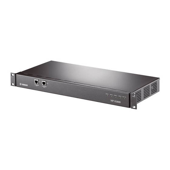
Page 16: Connections And Displays
ETH 2 RJ45 socket for a redundant connection to the network or to an iSCSI system LEDs, status information for the VIP X1600 modules and the VIP X1600 base NOTICE! For more information about the LEDs, see Section 8.4 LEDs, page 114. -
Page 17: Installation
CAUTION! Do not install a VIP X1600 module in a different housing and do not operate the unit outside of the VIP X1600 base. The ambient temperature during installation must be between 0 and +50 °C (+32 and +122 °F), and the relative humidity must not exceed 80% (non- condensing). - Page 18 Malfunctions may occur when the VIP X1600 is switched on without a functional module in Slot 1. You can install up to four VIP X1600 modules in a VIP X1600 base. Slot 1 must always be the first slot that is populated. The remaining slots can be populated in any order desired. It is also possible to install and remove modules during operation.
-
Page 19: Installing In A Switch Cabinet
Installing in a Switch Cabinet 4.3.1 Preparations The VIP X1600 is set up for installation in a 19-inch rack. The necessary installation equipment is included in the scope of delivery. CAUTION! When installing in a switch cabinet, ensure that there is sufficient ventilation for the unit. - Page 20 | Installation VIP X1600 V3.5 | 2007.12 Installation and Operating Manual Bosch Security Systems...
-
Page 21: Connections
4.4.2 Audio Connections The audio versions of the VIP X1600 modules contain two audio line inputs for a total of four mono inputs, which are automatically assigned to the four camera inputs. The audio signals are transmitted at the same time as the video signals. -
Page 22: Data Interface
4.4.7 Relay Outputs Each VIP X1600 module has four relay outputs for switching external units such as lamps or alarm sirens. You can operate these relay outputs manually while there is an active connection to the VIP X1600 module. The outputs can also be configured to automatically activate sirens or other alarm units in response to an alarm signal. -
Page 23: Power On/Power Off
Connect the VIP X1600 to a power supply unit and plug this into the mains. The unit is now ready for use. The VIP X1600 does not come supplied with a power supply unit. - Page 24 You can start the configuration if a VIP X1600 module is shown in the list in the left section of the window. To do this, click the entry for the module.
-
Page 25: Configuration Using A Web Browser
Configuration Using a Web Browser Connecting The integrated HTTP server in the VIP X1600 module offers you the option of configuring the unit over the network with a Web browser. This option is an alternative to configuration using the Configuration Manager program and is considerably richer in function and more convenient than configuration using the terminal program. - Page 26 5.1.3 Establishing the Connection At least the VIP X1600 module in Slot 1 must be assigned a valid IP address to operate the VIP X1600 on your network. The following default address is preset at the factory for all modules: 192.168.0.1 Start the Web browser.
-
Page 27: Configuration Menu
The settings in the configuration menu should only be processed or modified by expert users or system support personnel. All settings are stored in the VIP X1600 module's memory so that they are retained even if the power supply is interrupted. - Page 28 | Configuration Using a Web Browser VIP X1600 5.2.1 Starting Configuration Click the SETTINGS link in the upper section of the window. The Web browser opens a new page with the configuration menu. 5.2.2 Navigation Click one of the menu items in the left window margin. The corresponding submenu is displayed.
-
Page 29: Identification
5.3.1 Unit name You can give the VIP X1600 module a name to make it easier to identify. The name makes the task of administering multiple units in larger video monitoring systems easier, for example using the VIDOS or Bosch Video Management System programs. -
Page 30: Display Stamping
| Configuration Using a Web Browser VIP X1600 5.4.1 Camera 1 to Camera 4 Enter a unique, unambiguous name for the camera in this field. CAUTION! Do not use any special characters, for example &, in the name. Special characters are not supported by the system's internal recording management and may therefore result in the Player or Archive Player being unable to play back the recording. -
Page 31: Alarm Message
VIP X1600 Configuration Using a Web Browser | en 5.5.3 Alarm mode stamping Select On to display a text message overlay in the event of an alarm. It can be displayed at a position of your choice that you can then specify using the Custom option. Or it can be set to Off for no overlay information. -
Page 32: Password
The service user name is the highest authorization level. After entering the correct password, this user name allows you to use all the functions of the VIP X1600 module and change all configuration settings. The user user name is the middle authorization level. You use it to operate the unit and also to control cameras, for example, but you cannot change the configuration. -
Page 33: Language
— it is added automatically. Enter the current time or click the Synchr. PC button to copy your computer's system time to the VIP X1600 module. Bosch Security Systems Installation and Operating Manual... -
Page 34: Time Server
The VIP X1600 module in Slot 1 is the default time server for the modules in Slot 2 to Slot 4. In this case, the Time server IP address field can be empty for Slot 2 to Slot 4 (0.0.0.0). - Page 35 VIP X1600 Configuration Using a Web Browser | en 5.9.4 Time server type Select the protocol that is supported by the selected time server. Preferably, you should select the SNTP server as the protocol. This supports a high level of accuracy and is required for special applications and subsequent function extensions.
-
Page 36: Picture Settings
| Configuration Using a Web Browser VIP X1600 5.10 Picture Settings You can set the video image of each camera to suit your requirements. The current video image is displayed in the small window next to the slide controls as confirmation. Your changes are effective immediately. -
Page 37: Encoder Profile
You can adapt the MPEG-4 data transmission to the operating environment (for example network structure, bandwidth, data load). To this end, the VIP X1600 module simultaneously generates two data streams (Dual Streaming) for each video input. You can select the compression settings of these data streams individually, for example one setting for transmissions to the Internet and one for LAN connections. - Page 38 | Configuration Using a Web Browser VIP X1600 5.11.1 Active profile Here you can select the desired profile for each of the two streams. You will see a preview for each data stream in the right section of the window. The preview of the data stream currently selected is marked by a green frame.
-
Page 39: Profile Configuration
VIP X1600 Configuration Using a Web Browser | en 5.12 Profile Configuration You can change individual parameter values within a profile and you can also change the name. You can switch between profiles by clicking the appropriate tabs. CAUTION! The profiles are rather complex. They include a large number of parameters that interact with one another, so it is generally best to use the default profiles. -
Page 40: Target Data Rate
5.12.2 Target data rate You can limit the data rate for the VIP X1600 module to optimize utilization of the bandwidth in your network. The target data rate should be set according to the desired picture quality for typical scenes with no excessive motion. - Page 41 VIP X1600 Configuration Using a Web Browser | en 5.12.8 I-frame distance This parameter allows you to set the intervals in which the I-frames will be coded. 0 means auto mode, whereby the video server inserts I-frames as necessary. An entry of 1 indicates that I-frames are continuously generated.
-
Page 42: Video Input
5.13 Video Input You can activate the 75 Ohm terminating resistance for each video input on the VIP X1600 module. The terminating resistance must be deactivated for the video signal to be looped through. Every video input is closed at the time of delivery. -
Page 43: Audio (Audio Versions Only)
VIP X1600 Configuration Using a Web Browser | en 5.14 Audio (Audio Versions only) You can set the gain of the audio signals to suit your specific requirements. The current video image is shown in the small window next to the slide controls to help you check the selected audio source and improve assignments. -
Page 44: Jpeg Posting
| Configuration Using a Web Browser VIP X1600 5.15 JPEG Posting You can save individual JPEG images on an FTP server at specific intervals. You can then retrieve these images at a later date to reconstruct alarm events if required. - Page 45 VIP X1600 Configuration Using a Web Browser | en 5.15.3 Posting interval Enter the interval in seconds at which the images will be sent to an FTP server. Enter zero if you do not want any images to be sent.
-
Page 46: Storage Medium
5.16 Storage Medium You can record the images from the cameras connected to the VIP X1600 module in the RAM memory of the module or on an appropriately configured iSCSI system. The internal RAM memory is suitable for short-term recordings and pre-alarm recordings in ring mode operation. -
Page 47: Iscsi
VIP X1600 Configuration Using a Web Browser | en 5.17 iSCSI If you select type iSCSI system as the storage medium, you then need to set up a connection to the desired iSCSI system and set the configuration parameters. NOTICE! The storage system selected must be available on the network and completely set up. - Page 48 In cases where the information cannot be read due to the network topology, you must enter the data manually, so that the VIP X1600 module can access the drive. In this case you should ensure that the entries correspond exactly with the configuration of the iSCSI system.
- Page 49 Decoupling the Drive in Use Each drive can only be associated with one user. If a drive is already being used by another user, you can decouple the user and connect the drive with the VIP X1600 module. CAUTION! Before decoupling, make absolutely sure that the previous user no longer needs the drive.
-
Page 50: Partitioning
5.18 Partitioning Four partitions can be set up for recordings of the cameras connected to the VIP X1600 module; this is similar to the partitioning often found on computer hard drives. Parameters such as size and type of video recording can be specified for each partition. Modifying these parameters leads to reorganization, during which stored data is lost. -
Page 51: Creating A Partition
VIP X1600 Configuration Using a Web Browser | en 5.18.1 Creating a Partition NOTICE! The maximum number of partitions is predefined and corresponds to the number of video inputs on the module. You can create multiple partitions of the same type in one process. To do this, check the box Apply same settings for all new partitions in the first window. -
Page 52: Partition Status
| Configuration Using a Web Browser VIP X1600 5.18.2 Saving Changes After you have made all necessary settings, you must transfer the settings to the unit and save them. CAUTION! All modifications to settings are only effective if you complete the configuration in the last window by clicking Finish. -
Page 53: Editing A Partition
VIP X1600 Configuration Using a Web Browser | en 5.18.4 Editing a Partition You can modify the configuration of a partition at any time. CAUTION! All modifications result in the reorganization of the partition and all sequences stored on it are therefore lost. -
Page 54: Alarm Track Size
| Configuration Using a Web Browser VIP X1600 5.18.8 Number of alarm tracks CAUTION! Alarm tracks must be set up in the required partition for alarm recording. The unit uses a special recording mode during alarm recording for optimal usage of storage capacity: as soon as a time gap for alarm recording begins, a recording is continuously made on one segment, which is the size of a complete alarm sequence (pre- and post-alarm time). -
Page 55: Recording Profiles
VIP X1600 Configuration Using a Web Browser | en 5.19 Recording Profiles You can define up to ten different recording profiles. You will then use these recording profiles in the recording scheduler, where they are linked with the individual days and times (see Section 5.20 Recording Scheduler, page 57). -
Page 56: Standard Profile
Section 5.21 Alarm Sources, page 59). The numbering of the checkboxes for the alarm inputs corresponds to the labeling of the alarm inputs on the VIP X1600 module. The motion and video alarm numbers correspond to the labeling of the video inputs. -
Page 57: Recording Scheduler
VIP X1600 Configuration Using a Web Browser | en 5.20 Recording Scheduler The recording scheduler allows you to link the created recording profiles with the days and times at which the images of selected cameras are to be recorded in the event of an alarm. - Page 58 5.20.5 Recording status The graphic indicates the recording activity of the VIP X1600 module. You will see an animated graphic while recording is taking place. V3.5 | 2007.12 Installation and Operating Manual...
-
Page 59: Alarm Sources
Configuration Using a Web Browser | en 5.21 Alarm Sources You can configure the alarm inputs of the VIP X1600 module. 5.21.1 Alarm input Select Active high if the alarm is to be triggered by closing the contact. Select Active low if the alarm is to be triggered by opening the contact. -
Page 60: Alarm Connections
5.22 Alarm Connections You can select how the VIP X1600 module responds to an alarm. In the event of an alarm, the unit can automatically connect to a pre-defined IP address. You can enter up to ten IP addresses which the VIP X1600 module will contact in order in the event of an alarm, until a connection is made. - Page 61 NOTICE! If you enter the destination IP address 0.0.0.0 for destination 10, the VIP X1600 module will no longer use this address for the tenth attempt at automatic connection in the event of an alarm. The parameter is then used only to save the general password.
-
Page 62: Ssl Encryption
NOTICE! Please note that the SSL encryption must be activated and configured at both ends of a connection. This requires the appropriate certificates to be uploaded onto the VIP X1600 module (see Section 5.36.4 Maintenance log, page 90). You can activate and configure encryption of the media data (video, audio and metadata) on the Encryption page (see Section 5.30 Encryption, page 81). -
Page 63: Vca
Configuration Using a Web Browser | en 5.23 The VIP X1600 modules feature an integrated video content analysis (VCA), which can detect and analyze changes in the signal. Such changes can be due to movements in the camera's field of view. - Page 64 If you select one of these algorithms, you can set the corresponding parameters here directly. You can find information on this in the relevant documents on the product CD supplied (see Section 3.2 Scope of Delivery of VIP X1600 Module, page 11). 5.23.3...
- Page 65 VIP X1600 Configuration Using a Web Browser | en 5.23.4 Sensitivity (MOTION+ only) The basic sensitivity of the motion detector can be adjusted for the environmental conditions to which the camera is subject. The sensor reacts to variations in the brightness of the video image. The darker the observation area, the higher the value that must be selected.
-
Page 66: Tamper Detection
| Configuration Using a Web Browser VIP X1600 5.23.7 Tamper Detection You can reveal the tampering of cameras and video cables by means of various options. Run a series of tests at different times of the day and night to ensure that the video sensor is operating as intended. -
Page 67: Select Area
VIP X1600 Configuration Using a Web Browser | en 5.23.13 Scene too noisy Activate this function if tampering associated with EMC interference (noisy scene as the result of a strong interference signal in the vicinity of the video lines), as an example, should trigger an alarm. -
Page 68: Alarm E-Mail
As an alternative to automatic connecting, alarm states can also be documented by e-mail. In this way it is possible to notify a recipient who does not have a video receiver. In this case the VIP X1600 module automatically sends an e-mail to a previously defined e-mail address. 5.24.1 Send alarm e-mail Select On if you want the unit to automatically send an alarm e-mail in the event of an alarm. - Page 69 VIP X1600 Configuration Using a Web Browser | en 5.24.6 Attach JPEG from camera Click the checkbox to specify the cameras from which JPEG images are sent. An enabled video input is indicated by a check mark. 5.24.7 Destination address Enter the e-mail address for alarm e-mails here.
-
Page 70: Alarm Task Editor
Alarm Task Script Language document. You can find the document on the product CD supplied (see Section 3.2 Scope of Delivery of VIP X1600 Module, page 11). As an alternative to the alarm settings on the various alarm pages, you can enter your desired alarm functions in script form here. -
Page 71: Relay Settings
VIP X1600 Configuration Using a Web Browser | en 5.26 Relay Settings You can configure the switching behavior of the relay outputs. For each relay, you can specify an open switch relay (normally closed contact) or a closed switch relay (normally open contact). - Page 72 Trigger by remote station's corresponding switching contact (only if a connection exists) NOTICE! The numbers in the lists of selectable events relate to the corresponding connections on the VIP X1600 module, Video alarm 1, for example to the Video In 1 connection. 5.26.4 Relay name You can assign a name for the relay here.
-
Page 73: Com1
NOTICE! If the VIP X1600 module is working in multicast mode (see Section 5.29 Multicasting, page 79), the first remote location to establish a video connection to the unit is also assigned the transparent data connection. However, after about 15 seconds of inactivity the data connection is automatically terminated and another remote location can exchange transparent data with the unit. -
Page 74: Baud Rate
| Configuration Using a Web Browser VIP X1600 5.27.2 Camera ID If necessary, enter the ID of the peripheral you wish to control (for example a dome camera or pan/tilt head). The entered ID relates to the peripheral that is connected to the first video input. -
Page 75: Network
VIP X1600 Configuration Using a Web Browser | en 5.28 Network The settings in this screen are used to integrate the VIP X1600 module into an existing network. Bosch Security Systems Installation and Operating Manual V3.5 | 2007.12... -
Page 76: Ip Address
DNS server address The VIP X1600 module is easier to access if the unit is listed on a DNS server. If you wish, for example, to establish an Internet connection to the VIP X1600 module, it is sufficient to enter the name given to the unit on the DNS server as a URL in the browser. - Page 77 You can specify a higher MSS value for a connection to the iSCSI system than for the other data traffic via the network. The potential value depends on the network structure. A higher value is only useful if the iSCSI system is located in the same subnet as the VIP X1600. Bosch Security Systems Installation and Operating Manual V3.5 | 2007.12...
- Page 78 Settings for authentication are only neccessary for the module in slot 1. This makes for the automatic authentication of the other modules. To configure the unit, you must connect the VIP X1600 directly to a computer using a network cable. This is because communication via the network is not enabled until the Identity and Password parameters have been set and successfully authenticated.
-
Page 79: Multicasting
In addition to a 1:1 connection between an encoder and a single receiver (unicast), the VIP X1600 modules can enable multiple receivers to receive the video signal from an encoder simultaneously. The module either duplicates the data stream itself and then distributes it to multiple receivers (multi-unicast) or it sends a single data stream to the network, where the data stream is simultaneously distributed to multiple receivers in a defined group (multicast). - Page 80 (duplication of the data streams in the network). With the setting 0.0.0.0 the encoder for the relevant stream operates in multi-unicast mode (copying of data streams in the unit). The VIP X1600 modules support multi-unicast connections for up to five simultaneously connected receivers.
-
Page 81: Encryption
VIP X1600 Configuration Using a Web Browser | en 5.30 Encryption A special license, with which you will receive a corresponding activation key, is required to encrypt user data. You can enter the activation key to release the function on the Licenses page (see Section 5.35 Licenses, page 88). -
Page 82: Automatic Key Interchange
| Configuration Using a Web Browser VIP X1600 5.30.1 Encryption From the Encryption list field, select the On option to activate the encryption. Keys will then be generated for all data channels. Click the Keys >> button. The keys for the individual data channels will be displayed. -
Page 83: Version Information
VIP X1600 Configuration Using a Web Browser | en 5.31 Version Information The data on this page are for information purposes only and cannot be changed. Keep a record of this information in case technical assistance is required. NOTICE! You can select all required text on this page with the mouse and copy it to the clipboard with the [Ctrl]+[C] key combination, for example if you want to send it via e-mail. -
Page 84: Livepage Configuration
When accessing via the Internet/Intranet, ensure that a connection is always available to display the image. The image file is not stored in the VIP X1600 module. Check the box for the items that are to be displayed on the LIVEPAGE. The selected items are indicated by a check mark. - Page 85 VIP X1600 Configuration Using a Web Browser | en 5.32.1 Company logo Enter the path to a suitable graphic if you want to replace the manufacturer's logo. The image file can be stored on a local computer, in the local network or at an Internet address.
- Page 86 | Configuration Using a Web Browser VIP X1600 5.32.8 JPEG size You can choose between two given image sizes to display the M-JPEG image. 5.32.9 JPEG interval You can specify the interval at which the individual images should be generated for the M- JPEG image.
-
Page 87: System State
This window is only visible for a VIP X1600 module in Slot 1. 5.34.1 Check power redundancy Select the option On if the VIP X1600 is to be supplied by two power supply units. This selection is important for displaying the power supply status messages correctly. Bosch Security Systems Installation and Operating Manual V3.5 | 2007.12... -
Page 88: Licenses
| Configuration Using a Web Browser VIP X1600 5.35 Licenses You can enter the activation key to enable additional functions or software modules in this window. NOTICE! The activation key cannot be deactivated again and is not transferable to other units. -
Page 89: Maintenance
If the LED of the corresponding module on the front panel of the VIP X1600 is showing red, the upload has failed and must be repeated. To perform the upload you must now switch to a special page: In the address bar of your browser, enter /main.htm after the IP address of the VIP X1600... -
Page 90: Ssl Certificate
VIP X1600 5.36.2 Configuration You can save configuration data for the VIP X1600 module on a computer and then load saved configuration data from a computer to the module. Upload Enter the full path of the file to upload or click Browse to select the required file. -
Page 91: Function Test
The VIP X1600 offers a variety of configuration options. You should therefore check that it is functioning correctly after installation and configuration. The function test is the only way to ensure that the VIP X1600 operates as expected in the event of an alarm. - Page 92 | Configuration Using a Web Browser VIP X1600 V3.5 | 2007.12 Installation and Operating Manual Bosch Security Systems...
-
Page 93: Operation
Operation | en Operation Operation with Microsoft Internet Explorer A computer with Microsoft Internet Explorer (version 6.0 or higher) can receive live images from the VIP X1600 modules, control cameras or other peripherals and replay saved video sequences. 6.1.1 System Requirements –... - Page 94 VIP X1600 6.1.3 Establishing the Connection At least the VIP X1600 module in Slot 1 must be assigned a valid IP address to operate the VIP X1600 on your network. The following default address is preset at the factory: 192.168.0.1 Start the Web browser.
-
Page 95: The Livepage
If you do not connect, the unit may have reached its maximum number of connections. Depending on the unit and network configuration, each VIP X1600 module can have up to 25 Web browser connections or up to 50 connections via VIDOS or Bosch Video Management System. -
Page 96: Image Selection
In the upper section of the window, click one of the links Module 1 to Module 4 to switch to the corresponding module in the same VIP X1600. NOTICE! A VIP X1600 module that is installed in another VIP X1600 must be selected via its IP address. 6.2.5 Image Selection You can view the image from each camera separately on a full screen. - Page 97 Control options for peripherals (for example a pan/tilt camera head or dome camera) depend on the type of unit installed and on the VIP X1600 module's configuration. If a controllable unit is configured and connected to the VIP X1600 module, the controls for the peripheral are displayed next to the video image.
- Page 98 6.2.9 System Log / Event Log The System Log field contains information about the operating status of the VIP X1600 module and the connection. You can save these messages automatically in a file (see Section 5.32 Livepage Configuration, page 84).
-
Page 99: Saving Snapshots
Click the icon for saving single images. The image is saved at a resolution of 704 × 576 pixels (4CIF). The storage location depends on the configuration of the VIP X1600 module (see Section 5.32.17 Path for JPEG and MPEG files, page 86). Recording Video Sequences You can save sections of the video sequence currently shown on the LIVEPAGE on your computer's hard drive. -
Page 100: Running Recording Program
100 en | Operation VIP X1600 Running Recording Program The hard drive icon below the camera images on the LIVEPAGE changes during an automatic recording. A moving graphic will appear to indicate a running recording. If no recording is taking place, a static icon is displayed. -
Page 101: The Recordings Page
VIP X1600 Operation | en 101 The RECORDINGS Page The RECORDINGS page for playing back recorded video sequences can be accessed from the LIVEPAGE and from the SETTINGS menu. The RECORDINGS link is only visible if a storage medium has been selected (see Section 5.16 Storage Medium, page 46). -
Page 102: Controlling A Playback
102 en | Operation VIP X1600 6.6.2 Controlling a Playback You will see a time bar below the video image for quick orientation. If a particular sequence has been clicked and selected for playback, the selected sequence is marked in the list. The associated time interval is displayed in the bar in gray. - Page 103 VIP X1600 Operation | en 103 6.6.4 Slide Control You can use the slide control to control playback speed and fast forward/rewind: positioning in the middle indicates playback at recording speed, left indicates rewind, and right fast forward. The fast forward or rewind speed changes, depending on how far you move the slide control toward the runner icons.
-
Page 104: Backup
The single images are immediately displayed in the Screenshots area after clicking. The storage location for the sequences and single images can be specified in the configuration of the VIP X1600 module (see Section 5.32.17 Path for JPEG and MPEG files, page 86). 6.7.1 Printing a Screenshot You can view and print the saved screenshots individually. -
Page 105: Installing The Player
Operation | en 105 Installing the Player You can play back saved video sequences using the Player from Bosch Security Systems, which can be found on the product CD supplied (see Section 3.1 Scope of Delivery of VIP X1600 Base, page 11). NOTICE! In order to play back saved sequences using the Player, suitable MPEG ActiveX software must be installed on the computer. -
Page 106: Hardware Connections Between Video Servers
VIP X1600 Hardware Connections Between Video Servers You can easily connect a VIP X1600 with connected cameras as a sender, and a suitable MPEG-4 compatible hardware decoder (for example VIP XD) with a connected monitor as a receiver via an Ethernet network. In this way it is possible to cover long distances without the need for major installation or cabling work. - Page 107 Enter the command 4 in the IP menu to change the remote IP address, then enter the IP address of the VIP X1600 module you wish to connect to. Enter the command 0 to return to the main menu and then enter the command 4 to switch to the Rcp+ menu.
-
Page 108: Operation Using Software Decoders
Bosch range, benefiting from a complete security solution based on the latest technology and years of experience. The VIP X1600 video server is also designed for use with the DiBos 8 digital recorder. DiBos 8 records up to 32 video and audio streams and is available as IP software or hybrid DVR with additional analog camera and audio inputs. -
Page 109: Maintenance And Upgrades
Unit Reset You can use the Factory Reset button to restore a VIP X1600 module to its original settings. Any changes to the settings are overwritten by the factory defaults. A reset may be necessary, for example, if the unit has invalid settings that prevent it from functioning as desired. -
Page 110: Repairs
VIP X1600 Repairs CAUTION! Do not change any components in the VIP X1600 module or VIP X1600 base. The unit does not contain any user-serviceable parts. Ensure that all maintenance or repair work is carried out only by qualified personnel (electrical engineers or network technology specialists). -
Page 111: Appendix
If you are unable to resolve a malfunction, please contact your supplier or system integrator, or go directly to Bosch Security Systems Customer Service. You can view a range of information about your unit version on the Version Information page (see Section 5.31 Version Information, page 83). -
Page 112: General Malfunctions
112 en | Appendix VIP X1600 General Malfunctions Malfunction Possible causes Recommended solution No connection between Incorrect cable connections. Check all cables, plugs, module and terminal contacts, terminals and program. connections. The computer's serial interface Check the other serial interface. -
Page 113: Malfunctions With Iscsi Connections
VIP X1600 Appendix | en 113 Malfunction Possible causes Recommended solution The module does not Alarm source is not selected. Select possible alarm sources on report an alarm. the Alarm Sources configuration page. No alarm response specified. Specify the desired alarm... -
Page 114: Leds
Defect in fans or redundant power supply unit. Processor Load If the VIP X1600 is accessed via the Web browser, you will see the module's processor load indicators in the top left of the window next to the manufacturer's logo. -
Page 115: Serial Interface
VIP X1600 Appendix | en 115 Serial Interface Options for using the serial interface include transferring transparent data, controlling connected units or operating the unit with a terminal program. The serial interface supports the RS232, RS422 and RS485 transmission standards. The mode used depends on the current configuration (see Section 5.27 COM1, page 73). -
Page 116: Communication With Terminal Program
8.8.1 Data Terminal If a VIP X1600 module cannot be found in the network or the connection to the network is interrupted, you can connect a data terminal to the VIP X1600 module for initial setup and setting of important parameters. The data terminal consists of a computer with a terminal program. - Page 117 Appendix | en 117 8.8.4 Assigning an IP Address To use a VIP X1600 module in your network, you must assign it an IP address that is valid for your network. The following default address is preset at the factory: 192.168.0.1 Start a terminal program such as HyperTerminal.
- Page 118 118 en | Appendix VIP X1600 V3.5 | 2007.12 Installation and Operating Manual Bosch Security Systems...
-
Page 119: Glossary
VIP X1600 Glossary | en 119 Glossary Symbols 10/100/1000 Base-T IEEE-802.3 specification for 10, 100 or 1000 Mbps Ethernet 802.1x The IEEE 802.1x standard provides a general method for authentication and authorization in IEEE-802 networks. Authentication is carried out via the authenticator, which checks the transmitted authentication information using an authentication server (see RADIUS server) and approves or denies access to the offered services (LAN, VLAN or WLAN) accordingly. - Page 120 120 en | Glossary VIP X1600 Identification: a machine readable character string IEEE Institute of Electrical and Electronics Engineers IGMP Internet Group Management Protocol Internet Protocol The main protocol used on the Internet, normally in conjunction with the Transfer Control...
- Page 121 VIP X1600 Glossary | en 121 Network Time Protocol; a standard for synchronizing computer system clocks via packet- based communication networks. NTP uses the connectionless network protocol UDP. This was developed specifically for enabling time to be reliably transmitted over networks with variable packet runtime (Ping).
- Page 122 122 en | Glossary VIP X1600 Unshielded Twisted Pair See Wide area network Wide area network A long distance link used to extend or connect remotely located local area networks V3.5 | 2007.12 Installation and Operating Manual Bosch Security Systems...
-
Page 123: Specifications
Dimensions (H × W × D) 44 × 440 × 210 mm / 1.73 × 17.32 × 8.27 in, including BNC module connections Weight Approx. 4 kg / 8.82 lb with 4 VIP X1600 modules Bosch Security Systems Installation and Operating Manual V3.5 | 2007.12... -
Page 124: Vip X1600 Module
124 en | Specifications VIP X1600 10.2 VIP X1600 Module Operating voltage Supply via VIP X1600 base housing Power consumption Max. 12 W Data interfaces 1 × RS232/RS422/RS485, bidirectional, push-in terminal RAM memory 8 MB per channel Alarm inputs 4 × push-in terminals (non-isolated closing contact),... -
Page 125: Protocols/Standards
VIP X1600 Specifications | en 125 10.3 Protocols/Standards Video standards PAL, NTSC Video coding protocols MPEG-4, M-JPEG, JPEG Video data rate 9.6 kbps to 6 Mbps Image resolutions (PAL/NTSC) 704 × 576/480 pixels (4CIF/D1) 704 × 288/240 pixels (2CIF) 464 × 576/480 pixels (2/3 D1) 352 ×... - Page 126 126 en | Specifications VIP X1600 V3.5 | 2007.12 Installation and Operating Manual Bosch Security Systems...
-
Page 127: Index
VIP X1600 Index | en 127 Index Default profile 40 Defaults 55 Activating the recording 58 Deleting recordings 54 Activation key 88 Display stamping 30 Actuator 22 Dome camera 22 Alarm 16 Dual Streaming 13 Alarm e-mail 68 Alarm input 22... - Page 128 128 en | Index VIP X1600 Livepage 84 Receiver password 61 Low Voltage Directive 8 Recording profiles 55 Low-pass filter 36 Recording program 100 Recording scheduler 57 Recording status 58 Main functions 15 Recording video sequences 99 Maintenance 9 Reflections of light 64...
- Page 129 VIP X1600 Index | en 129 Time server protocol 34 Time signal 34 Time zone 34 TLS 77 Transfer protocol 61 Transmission parameters 116 Transmission rate 74 Transmission standards 22 Transparent 73 Traps 78 Trigger relay 72 TTL 80 UDP 61...
- Page 130 130 en | Index VIP X1600 V3.5 | 2007.12 Installation and Operating Manual Bosch Security Systems...
- Page 132 Bosch Security Systems Robert-Koch-Straße 100 D-85521 Ottobrunn Germany Telefon 089 6290-0 089 6290-1020 www.bosch-securitysystems.com © Bosch Security Systems, 2007...
Need help?
Do you have a question about the VIP X1600 and is the answer not in the manual?
Questions and answers