
Related Manuals for Bosch DSA-N2E7X2-08AT


Summary of Contents for Bosch DSA-N2E7X2-08AT
- Page 1 DSA E-Series (E2700) DSA-N2E7X2-08AT | DSA-N2E7Xx-12AT | DSA-N2C7Xx-12AT | DSX-N1D6Xx-12AT | DSX-N6D6Xx-60AT | DSX-NRCK40-INT Installation manual...
-
Page 3: Table Of Contents
Things to know – drive tray cabling configurations for the E2712 controller-drive tray Connecting the ethernet cables 10.1 Key terms 10.2 Things to know – connecting Ethernet cables 10.3 Procedure – connecting Ethernet cables Bosch Sicherheitssysteme GmbH Installation manual 2016.12 | V2.1 | DOC... - Page 4 12.12 Things to know – seven-segment display use cases 12.13 Things to know – seven-segment display for the ESMs on the drive trays Regulatory compliance statements Trademark information Additional documentation 2016.12 | V2.1 | DOC Installation manual Bosch Sicherheitssysteme GmbH...
-
Page 5: Safety
– Pluggable devices must have an easily accessible socket-outlet installed near the equipment. – Unplug the unit from the outlet before cleaning. Follow any instructions provided with the unit. Bosch Sicherheitssysteme GmbH Installation manual 2016.12 | V2.1 | DOC... - Page 6 SELV circuits. – If safe operation of the unit cannot be ensured, remove it from service and secure it to prevent unauthorized operation. In such cases, have the unit checked by Bosch Security Systems. –...
-
Page 7: Warning Notices
DO NOT disassemble, heat above 60ºC (140ºF), crush or puncture, short circuit external contacts, or dispose of in fire or water. Use appropriate charger only. Replace only with original batteries. Bosch Sicherheitssysteme GmbH Installation manual 2016.12 | V2.1 | DOC... - Page 8 Do not use equipment in the cabinet as a shelf or work space. Warning! Hazardous moving parts Keep away from moving fan blades. Warning! Risk of bodily injury High leakage current earth connection essential before connecting supply. 2016.12 | V2.1 | DOC Installation manual Bosch Sicherheitssysteme GmbH...
-
Page 9: Caution Notices
Notices Notice! This is a class A product. In a domestic environment this product may cause radio interference, in which case the user may be required to take adequate measures. Bosch Sicherheitssysteme GmbH Installation manual 2016.12 | V2.1 | DOC... - Page 10 DSA E-Series (E2700) Notice! Video loss is inherent to digital video recording; therefore, Bosch Security Systems cannot be held liable for any damage that results from missing video information. To minimize the risk of losing information, we recommend multiple, redundant recording systems, and a procedure to back up all analog and digital information.
-
Page 11: About This Guide
For simplicity, the following product names will be used for the following units also described in this manual: – DE1600 for the DSA E‑Series 12-bay expansion unit – DE6600 for the DSA E‑Series 60-bay expansion unit See also – Additional documentation, page 77 Bosch Sicherheitssysteme GmbH Installation manual 2016.12 | V2.1 | DOC... -
Page 12: Registering For E-Series
Record the serial number of the integrated controller-drive tray for later use. This serial number is required to initiate any support request for your system. Notice! The SANtricity® Storage Manager software is also referred to as the storage management software. 2016.12 | V2.1 | DOC Installation manual Bosch Sicherheitssysteme GmbH... -
Page 13: Preparing For An E2700 Controller-Drive Tray Installation
Use the tables in this section to verify that you have all of the necessary items to install the controller-drive tray. Notice! Possible hardware damage To prevent electrostatic discharge damage to the tray, use proper antistatic protection when handling tray components. 4.2.1 Basic hardware Item Bosch Sicherheitssysteme GmbH Installation manual 2016.12 | V2.1 | DOC... -
Page 14: E2700 Configuration Cables And Connectors
Your cabinet might have special power cords that you use instead of the power cords that ship with the controller-drive tray and the drive trays. RJ-45 Ethernet cable This cable is used for 10-Gb/s iSCSI connections. 2016.12 | V2.1 | DOC Installation manual Bosch Sicherheitssysteme GmbH... -
Page 15: Tools And Other Items
The controller-drive tray supports SAS drive connections and SAS, or iSCSI host connections. Notice! Your cables might look slightly different from the ones shown. The differences do not affect the performance. 10-Gb/s iSCSI cable connection Bosch Sicherheitssysteme GmbH Installation manual 2016.12 | V2.1 | DOC... -
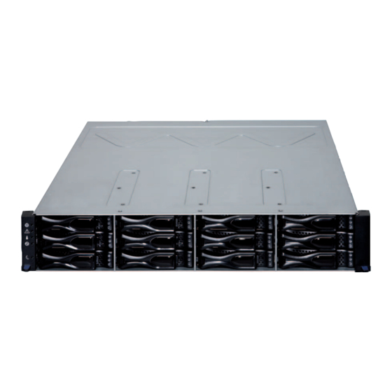
Page 16: Things To Know -Taking A Quick Glance At The Hardware In A E2700 Controller-Drive Tray
E2700 controller-drive tray – front view 97001-03 End cap Locate LED End cap Service action required LED End cap over-temperature LED End cap Power LED End cap Standby power LED Drive canister 2016.12 | V2.1 | DOC Installation manual Bosch Sicherheitssysteme GmbH... - Page 17 SFF-8644 SAS connector 1 (expansion) Power-fan canister Battery service action required LED Battery charging LED Controller service action allowed LED Controller service action required LED Cache active LED AC power connector On/off switch Bosch Sicherheitssysteme GmbH Installation manual 2016.12 | V2.1 | DOC...
- Page 18 To avoid exceeding the functional and environmental limits, install only drives that have been provided or approved by the original manufacturer. System integrators, resellers, system administrators, or users of the controller-drive tray can install the drives. 2016.12 | V2.1 | DOC Installation manual Bosch Sicherheitssysteme GmbH...
- Page 19 Expansion port SFF-8088 connector 1 (IN) Expansion port SFF-8088 connector 2 (IN) Seven-segment display indicators Serial connector Ethernet connector Expansion port SFF-8088 connector (OUT) Power-fan canister Power connector Power switch ESM B canister Bosch Sicherheitssysteme GmbH Installation manual 2016.12 | V2.1 | DOC...
- Page 20 DE6600 drive tray – front view with bezel removed 92034-04 DE6600 drive tray – rear view 92056-07 Fan canisters ESM A ESM B Expansion port SFF-8088 connectors (IN) Expansion port SFF-8088 connector (OUT) Power canisters 2016.12 | V2.1 | DOC Installation manual Bosch Sicherheitssysteme GmbH...
-
Page 21: Ethernet Network Interface Cards For The E2700 Controller-Drive Tray
Ethernet network interface cards for the E2700 controller-drive tray | en Ethernet network interface cards for the E2700 controller-drive tray The E2700 controller-drive tray supports a two-port 10-Gb/s iSCSI Base-T HIC host interface cards. Bosch Sicherheitssysteme GmbH Installation manual 2016.12 | V2.1 | DOC... -
Page 22: Installing The E2700 Controller-Drive Tray
Make sure that the cabinet is in the final location. Make sure that the cabinet installation site meets the clearance requirements. Note: Fans pull air through the tray from front to back across the drives. 2016.12 | V2.1 | DOC Installation manual Bosch Sicherheitssysteme GmbH... - Page 23 2 - Existing tray 3 - Clearance above and below the existing tray 4 - Screws for securing the mounting rail to the cabinet (front and rear) 5 - Industry standard cabinet Bosch Sicherheitssysteme GmbH Installation manual 2016.12 | V2.1 | DOC...
- Page 24 Insert two M5 screws through the rear of the cabinet and into the captured nuts in the rear flange in the mounting rail. Tighten the screws. – Tighten the adjustment screws on the mounting rail. – Repeat the substeps to install the second mounting rail. 2016.12 | V2.1 | DOC Installation manual Bosch Sicherheitssysteme GmbH...
- Page 25 Gently press on the bottom of the end cap until it snaps into place over the retainer on the bottom of the controller-drive tray mounting flange. 10. Install the drive trays. Bosch Sicherheitssysteme GmbH Installation manual 2016.12 | V2.1 | DOC...
-
Page 26: Procedure - Installing Drives In The E2712 Controller-Drive
Note: In some models, the drive handle might have the hinge on the right. 97006-01 1 - Drive handle Install the second drive beneath the first drive. Install the other drives from top to bottom and then from left to right. 2016.12 | V2.1 | DOC Installation manual Bosch Sicherheitssysteme GmbH... -
Page 27: Connecting The E2700 Controller-Drive Tray To The Hosts
Each controller has two native host ports. – In addition, you can have additional host ports that are located on a host interface card (HIC). Two iSCSI Base-T connectors at 10 Gb/s are supported. Bosch Sicherheitssysteme GmbH Installation manual 2016.12 | V2.1 | DOC... - Page 28 Host channels on the E2712 and E2712 controllers with a two-port iSCSI HIC – rear view Port 1 Port 2 iSCSI Host Drive Expansion iSCSI host interface card channel 3 - iSCSI host interface card channel 4 2016.12 | V2.1 | DOC Installation manual Bosch Sicherheitssysteme GmbH...
-
Page 29: Procedure - Connecting The Controller-Drive Tray To The Expansion Drive Trays
E2700 controller- drive tray. One expansion drive tray (simplex controller configuration) One expansion drive tray (dual simplex controller configuration) (recommended cabling for maximum throughput) Two expansion drive trays (dual simplex controller configuration) Bosch Sicherheitssysteme GmbH Installation manual 2016.12 | V2.1 | DOC... - Page 30 Affix a label to each end of the cable with the relevant information. A label is very important if you need to disconnect cables to service a controller. Include this information on the labels: 2016.12 | V2.1 | DOC Installation manual Bosch Sicherheitssysteme GmbH...
-
Page 31: Connecting To The Network
Repeat step 1 through step 4 for each controller and host channel that you intend to use. Connecting to the network In case of a Bosch Video Recording Solution a host is an IP camera. To connect the controller to the Ethernet one or two of two available iSCSI host ports must be connected to the Ethernet. - Page 32 Controller-drive tray with Controller A Ethernet Port 1 and Controller B Ethernet Port 2 (reserved) Notice! Ethernet port 2 should be reserved for maintenance operations if your hardware contains a second Ethernet port. 2016.12 | V2.1 | DOC Installation manual Bosch Sicherheitssysteme GmbH...
-
Page 33: Installing The Drive Trays For The E2700 Controller-Drive Tray Configurations
If the top half of the cabinet is too heavy for the bottom half, the cabinet might fall and cause bodily injury. Always install a component in the lowest available position in the cabinet. Bosch Sicherheitssysteme GmbH Installation manual 2016.12 | V2.1 | DOC... - Page 34 If you are installing the mounting rails above an existing tray, position the mounting rails directly above the existing tray. – If you are installing the mounting rails below an existing tray, allow 8.7-cm (3.4-in.) vertical clearance. 2016.12 | V2.1 | DOC Installation manual Bosch Sicherheitssysteme GmbH...
- Page 35 – Make sure that the alignment spacers on the front flange of the mounting rail fit into the mounting holes in the cabinet. Bosch Sicherheitssysteme GmbH Installation manual 2016.12 | V2.1 | DOC...
- Page 36 Secure the front of the drive tray to the cabinet. Use the two screws to attach the flange on each side of the front of the drive tray to the mounting rails. 2016.12 | V2.1 | DOC Installation manual Bosch Sicherheitssysteme GmbH...
-
Page 37: Procedure - Installing Drives In The De1600 Drive Trays
The installation order is from top to bottom and from left to right. The installation order is important for tray loss protection because the drives might already contain configuration information that depends upon the correct sequence of the drives in the tray. Bosch Sicherheitssysteme GmbH Installation manual 2016.12 | V2.1 | DOC... -
Page 38: Procedure - Installing The De6600 Drive Tray
An empty tray weighs approximately 56.7 kg (125 lb). Three persons are required to safely move an empty tray. If the tray is populated with components, a mechanized lift is required to safely move the tray. 2016.12 | V2.1 | DOC Installation manual Bosch Sicherheitssysteme GmbH... - Page 39 – Align the handle just under the thumb latch. – Push the handle up until it clicks in place with the thumb latch. Bosch Sicherheitssysteme GmbH Installation manual 2016.12 | V2.1 | DOC...
- Page 40 If you are installing the mounting rails above an existing tray, position the mounting rails directly above the tray. – If you are installing the mounting rails below an existing tray, allow 17.8 cm (7 in.) vertical clearance. 2016.12 | V2.1 | DOC Installation manual Bosch Sicherheitssysteme GmbH...
- Page 41 2 - Two M5 screws for the rear EIA support rail 3 - Front of the cabinet 4 - Two M5 screws for the front EIA support rail 5 - Adjustable rail tightening screws Bosch Sicherheitssysteme GmbH Installation manual 2016.12 | V2.1 | DOC...
- Page 42 – Place the mounting rail inside the cabinet, and extend the mounting rail until the flanges on the mounting rail touch the inside of the cabinet. 2016.12 | V2.1 | DOC Installation manual Bosch Sicherheitssysteme GmbH...
- Page 43 2 - Bottom cabinet mounting hole on the rear EIA support rail Remove the bezel from the front of the drive tray. WARNING (W09) Risk of bodily injury – Three persons are required to safely lift the component. Bosch Sicherheitssysteme GmbH Installation manual 2016.12 | V2.1 | DOC...
- Page 44 – Repeat the sub-step for the other side. Note: Make sure that each drive drawer in the drive tray is securely fastened to ensure proper air flow to the drives. 2016.12 | V2.1 | DOC Installation manual Bosch Sicherheitssysteme GmbH...
-
Page 45: Procedure - Installing Drives On The De6600 Drive Tray
All 60-drive trays have a limit of five solid state drives (SSDs) per drawer. If you exceed this limit for SSDs in a particular drawer, the power source in the drawer could fail. Bosch Sicherheitssysteme GmbH Installation manual 2016.12 | V2.1 | DOC... - Page 46 Starting with the first drive, raise the drive handle to the vertical position. 92037-03 Align the two raised buttons on each side over the matching gap in the drive channel on the drawer. 2016.12 | V2.1 | DOC Installation manual Bosch Sicherheitssysteme GmbH...
-
Page 47: Things To Know - Connecting The Power Cords
You can use the power cords shipped with the drive tray with typical outlets used in the destination country, such as a wall receptacle or an uninterrupted power supply (UPS). These power cords, however, are not intended for use in most EIA-compliant cabinets. Bosch Sicherheitssysteme GmbH Installation manual 2016.12 | V2.1 | DOC... -
Page 48: Procedure - Connecting The Power Cords
Make sure that both of the Power switches on the drive trays are turned off. Connect the primary power cords from the cabinet to the external power source. 92056.03 1 - Power switches 2016.12 | V2.1 | DOC Installation manual Bosch Sicherheitssysteme GmbH... -
Page 49: Connecting The E2700 Controller-Drive Tray To The Drive Trays
E2700 controller with base host channel ports (CH1 and CH2) 49006-16 See also – Procedure –turning on the power to the storage array and checking for problems in a E2700 controller-drive tray configuration, page 55 Bosch Sicherheitssysteme GmbH Installation manual 2016.12 | V2.1 | DOC... -
Page 50: Things To Know - Drive Trays
B. That is, the last drive tray in the chain from controller A must be the first drive tray in the chain from controller B. 2016.12 | V2.1 | DOC Installation manual Bosch Sicherheitssysteme GmbH... - Page 51 If you are connecting an ESM (Out) port to an ESM (IN) port, the label on the first drive tray will have this information: Dm1-ESM_A (left), OUT, DM1 ESM_B (left) Bosch Sicherheitssysteme GmbH Installation manual 2016.12 | V2.1 | DOC...
- Page 52 (recommended cabling for maximum throughput) One E2712 controller-drive tray and four drive trays E2700 Controller E2700 Controller Drive T ray Drive T ray Drive T ray Drive T ray 92057-15 2016.12 | V2.1 | DOC Installation manual Bosch Sicherheitssysteme GmbH...
-
Page 53: Connecting The Ethernet Cables
Connect one end of an Ethernet cable into the Ethernet port 1 on controller A. Connect the other end to the applicable network connection. Repeat step 1 through step 2 for controller B. Bosch Sicherheitssysteme GmbH Installation manual 2016.12 | V2.1 | DOC... -
Page 54: Connecting The Power Cords
AC power connector on each power canister in the drive tray. If you are installing other drive trays in the cabinet, connect a power cord to each power canister in the drive trays. 2016.12 | V2.1 | DOC Installation manual Bosch Sicherheitssysteme GmbH... -
Page 55: Turning On The Power And Checking For Problems In An E2700 Controller-Drive Tray
Check the LEDs on the front and the rear of the controller-drive tray and the attached drive trays. If you see any amber LEDs, make a note of their location. Bosch Sicherheitssysteme GmbH Installation manual 2016.12 | V2.1 | DOC... -
Page 56: Things To Know -Leds On The E2712 Controller-Drive Tray
Power is not present. Standby power Green The controller-drive tray is in Standby The controller-drive tray is Power mode. not in Standby Power mode. LEDs on the drive 89011-02 Location Color Blinking 2016.12 | V2.1 | DOC Installation manual Bosch Sicherheitssysteme GmbH... - Page 57 There is a 1000 Gb/s rate. There is a 10BASE-T rate. connector 2 link Ethernet Green The link is up (the LED blinks The link is not active. connector 2 link when there is activity). Bosch Sicherheitssysteme GmbH Installation manual 2016.12 | V2.1 | DOC...
- Page 58 For more information, see Things to know –seven segment display display sequence code definitions on the E2700 controller-drive tray, page 69. * After an AC power failure, this LED blinks while cache offload is in process. 2016.12 | V2.1 | DOC Installation manual Bosch Sicherheitssysteme GmbH...
- Page 59 Power-fan service Amber A fault exists within the Normal status. action required power-fan canister. Bosch Sicherheitssysteme GmbH Installation manual 2016.12 | V2.1 | DOC...
-
Page 60: Things To Know - General Behavior Of The Leds On The Controller-Drive Tray
On – The controller or the power- (fault) Power-fan canister fan canister needs attention. Off – The controller and the power- fan canister are operating normally. Locate Front frame On – Assists in locating the tray. 2016.12 | V2.1 | DOC Installation manual Bosch Sicherheitssysteme GmbH... - Page 61 AC power Power-fan Indicates that the power supply is Note: The LED is receiving AC power input. directly above or below the AC power switch and the AC power connector. Bosch Sicherheitssysteme GmbH Installation manual 2016.12 | V2.1 | DOC...
-
Page 62: Things To Know - Service Action Allowed Leds
When a service action is required for a controller canister, you must place that controller offline before removing it from the enclosure. This prerequisite ensures that the storage array maintains accurate expansion cabling. 2016.12 | V2.1 | DOC Installation manual Bosch Sicherheitssysteme GmbH... -
Page 63: Things To Know -Leds On The De6600 Drive Tray
The temperature of Normal status. temperature the drive tray has reached an unsafe level. Drive tray service Amber A component Normal status. action required within the drive tray needs attention. Bosch Sicherheitssysteme GmbH Installation manual 2016.12 | V2.1 | DOC... - Page 64 At least one of the four PHYs A link error has occurred. active in the Out port is working, and a link exists to the device connected to the Expansion Out connector. 2016.12 | V2.1 | DOC Installation manual Bosch Sicherheitssysteme GmbH...
- Page 65 A fault exists within the power Normal status. action required canister. Power AC power Green AC power to the power AC power to the power canister is present. canisteris not present. Bosch Sicherheitssysteme GmbH Installation manual 2016.12 | V2.1 | DOC...
-
Page 66: Leds On The De6600 Drive Drawers
Green The power is turned Drive I/O The power is turned drives 1 through 12 on, and the drive is activity is taking off. in the drive drawer operating normally. place. 2016.12 | V2.1 | DOC Installation manual Bosch Sicherheitssysteme GmbH... -
Page 67: Leds On The De6600 Drives
Drive tray On – Power is applied to the drive tray or ESM canister the canister. Power-fan canister Off – Power is not applied to the drive tray or the canister. Bosch Sicherheitssysteme GmbH Installation manual 2016.12 | V2.1 | DOC... - Page 68 On – The cable is attached and at least each expansion one lane has a link-up status. connector Off – The cable is not attached, or the cable is attached and all lanes have a link- down status. 2016.12 | V2.1 | DOC Installation manual Bosch Sicherheitssysteme GmbH...
-
Page 69: Things To Know -Seven Segment Display Sequence Code Definitions On The E2700
No codes appear, and the Diagnostic LED is off. 12.10 Things to know –seven segment component failure identifications for the E2700 controller-drive tray Use the seven segment display values to identify component. Bosch Sicherheitssysteme GmbH Installation manual 2016.12 | V2.1 | DOC... -
Page 70: Things To Know - Lock-Down Codes For The Controller-Drive Tray
A persistent hardware error has occurred, which results in a suspended controller state. A persistent data protection error has occurred, which results in a suspended controller state. 2016.12 | V2.1 | DOC Installation manual Bosch Sicherheitssysteme GmbH... - Page 71 The start-of-day (SOD) reboot limit has been exceeded, which results in a suspended controller state. The controller detects a checksum failure in EEPROM, which results in a suspended controller state. Bosch Sicherheitssysteme GmbH Installation manual 2016.12 | V2.1 | DOC...
-
Page 72: Things To Know - Seven-Segment Display Use Cases
Use case: Component failure when the controller is operational. – Failed host interface card OS+ CF+ HX+ blank- – Failed flash drive OS+ CF+ Fx+ blank- Use cases Repeating sequence Use case: Power-on diagnostic failure 2016.12 | V2.1 | DOC Installation manual Bosch Sicherheitssysteme GmbH... - Page 73 A cache memory diagnostic failure has been detected. dE+ L2+ "--"+ CF+ Cx + blank- A base controller diagnostic failure has been detected. dE+ L3+ "--"+ CF+ b1 + blank- Bosch Sicherheitssysteme GmbH Installation manual 2016.12 | V2.1 | DOC...
-
Page 74: Things To Know - Seven-Segment Display For The Esms On The Drive Trays
An ESM firmware failure has been detected. A non-catastrophic hardware failure has occurred. The ESM is operating in a Degraded state. The ESM canister is incompatible with the drive tray firmware. 2016.12 | V2.1 | DOC Installation manual Bosch Sicherheitssysteme GmbH... -
Page 75: Regulatory Compliance Statements
Bosch is not responsible for any damage or injury caused by unauthorized modification of this equipment or the substitution or attachment of connecting cables and equipment other than those specified by Bosch. -
Page 76: Trademark Information
All other brands or products are trademarks or registered trademarks of their respective holders and should be treated as such. NetApp, Inc. is a licensee of the CompactFlash and CF Logo trademarks. NetApp, Inc. NetCache is certified RealSystem compatible. 2016.12 | V2.1 | DOC Installation manual Bosch Sicherheitssysteme GmbH... -
Page 77: Additional Documentation
DSA E-Series (E2700) Additional documentation | en Additional documentation Documentation and software for Bosch Security Systems products can be found in the online product catalogue as follows: Open any browser > enter www.boschsecurity.com > select your region and your country >... - Page 80 Bosch Sicherheitssysteme GmbH Robert-Bosch-Ring 5 85630 Grasbrunn Germany www.boschsecurity.com © Bosch Sicherheitssysteme GmbH, 2016...
Need help?
Do you have a question about the DSA-N2E7X2-08AT and is the answer not in the manual?
Questions and answers