Cognex DataMan 475 Reference Manual
Verifier
Hide thumbs
Also See for DataMan 475:
- Reference manual (59 pages) ,
- Quick reference manual (18 pages) ,
- Reference manual (55 pages)
Table of Contents
Advertisement
Quick Links
Advertisement
Table of Contents

Related Manuals for Cognex DataMan 475


Summary of Contents for Cognex DataMan 475
- Page 1 ® DataMan 475 Verifier Reference Manual 2021 October 15 Revision: 6.2.5.18...
-
Page 2: Legal Notices
Copyright © 2021. Cognex Corporation. All Rights Reserved. Portions of the hardware and software provided by Cognex may be covered by one or more U.S. and foreign patents, as well as pending U.S. and foreign patents listed on the Cognex web site at: cognex.com/patents. -
Page 3: Table Of Contents
About the DataMan 475 Verifier Verifier Supporting Documentation DataMan 475 Verifier Verifier Accessories Cables and Power Supply Mounting Brackets DataMan 475 Verifier Systems Setting Up Your DataMan 475 Verifier Verifier Reader Layout Dimensions DataMan 475 Verifier Verifier DataMan 475 Verifier Verifier DPM Additional Information... - Page 4 Table of Contents Auto Aperture Calibration Settings Trending Settings User Information Report Settings Navigation Results through Setup Tool (local machine) Results through FTP Symbologies/Multi Mode Scripting Setting Up FTP Transfer Image FTP Transfer Result FTP Transfer Report FTP Transfer Grading Standards and their Parameters ISO/IEC 15415 Grading Parameters ISO/IEC 15416 (ANSI x3.182) Grading Parameters ISO 29158 (AIM-DPM) 2006 Grading Parameters...
-
Page 5: Symbols
Symbols Symbols The following symbols indicate safety precautions and supplemental information: WARNING: This symbol indicates a hazard that could cause death, serious personal injury or electrical shock. CAUTION: This symbol indicates a hazard that could result in property damage. Note: This symbol indicates additional information about a subject. Tip: This symbol indicates suggestions and shortcuts that might not otherwise be apparent. -
Page 6: Getting Started
Getting Started Getting Started This section provides general information about the DataMan 475 Verifier Verifier and the DataMan 475 Verifier Verifier accessories and systems. About the DataMan 475 Verifier Verifier The DataMan 475 Verifier Verifier provides immediate quality assurance benefits:... -
Page 7: Dataman 475 Verifier Verifier Accessories
The DataMan Reader Configuration Codes document provides printable 2-D codes that you can use to configure the DataMan verifier. Cognex->DataMan Software v x.x.x->Documentation->English->Reader Configuration Codes The DataMan 475 Verifier Verifier Quick Reference Guide provides essential information about the DataMan 475 Verifier verifier. Cognex->DataMan Software v x.x.x->Documentation->English->DM475V Series->DM475V Quick Reference... -
Page 8: Mounting Brackets
Accessory Name Accessory Product Number Accessory Illustration Mounting Bracket Kit DMBK-470-MNT Pivot Mounting Bracket DM100-PIVOTM-00 External Heat Sink DMHS-370-470 DataMan 475 Verifier Systems Symbologies Light Configurations Verification Standards DMV-475V-LBL-0200 1D, 2D, DPM 45° LabelLight ISO/IEC 15415, 15416, 29158 DMV-475V-DPM-0100 1D, 2D, DPM 30°, 45°, 90°... -
Page 9: Setting Up Your Dataman 475 Verifier Verifier
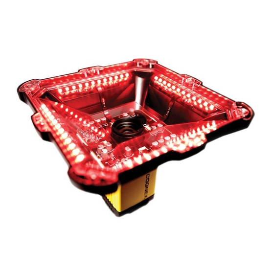
Setting Up Your DataMan 475 Verifier Verifier This section provides information on the physical appearance of the DataMan 475 Verifier verifier. It also details the steps of installing the lenses and filters of the verifier, and gives information on the imager. - Page 10 Setting Up Your DataMan 475 Verifier Verifier Item Description Power Train status Good/bad read Network Error Peak meter Indicator light ring SD card slot Tuning button Ethernet External light control Power, I/O, and RS-232 The table explains the indicator light ring behavior.
-
Page 11: Dimensions
Dimensions are in millimeters [inches] and are for reference purposes only. All specifications are for reference purposes only and can change without notice. Observe the following DataMan 475 Verifier verifier dimensions when installing your reader. DataMan 475 Verifier Verifier DataMan 475 Verifier Verifier DPM... -
Page 12: Additional Information
Setting Up Your DataMan 475 Verifier Verifier Additional Information DataMan475 Verifier and DPM Specifications Specification DataMan 475 Verifier DataMan 475V DPM Lighting Types 660 nm, 45o, 4-quadrant 660 nm, 45o, 4-quadrant 660 nm, 30o, 1-quadrant, 2- quadrant, 4-quadrant 660 nm, 90o Minimum X- 6 mil (0.15 mm) - Page 13 Setting Up Your DataMan 475 Verifier Verifier Specification DataMan 475 Verifier DataMan 475V DPM Vibration IEC 60068-2-6: vibration test in each of the three main axis for 2 (Shipping and hours @ 10 Gs (10 to 500 Hz at 100 m/s2 / 15 mm) with cables Storage) or cable plugs and appropriate lens cover attached.
-
Page 14: Led Wavelengths
Setting Up Your DataMan 475 Verifier Verifier DataMan 475 Series Verifier Imager Specifications Specification DataMan 475 Imager Image Sensor 2/3 inch CMOS, global shutter Image Sensor 8.8 mm x 6.6 mm (H x V); 3.45 µm square pixels Properties Image Resolution... -
Page 15: Calibration
Note: In an uncalibrated state, the verifier does not report aperture value, but uses the default aperture selection: Auto 50% for 1D applications or Auto 80% for 2D applications. To calibrate the DataMan 475 Verifier: 1. Click the Calibration icon in the top left corner in the TruCheck Verification window. - Page 16 6. If the calibration is successful, one of two messages pop-up. If you performed the calibration with one of the supported NIST-traceable calibration symbols, the pop-up displays the following : When you perform a successful calibration with a supported NIST-traceable calibration symbol, a calibration time date stamp appears on the bottom of the TruCheck window and is printed in the header of the report.
- Page 17 Supported NIST calibration symbols: 1D and 2D symbols on the Cognex Calibration Card (Cognex #DMV-CCC) Symbols 1 and 5 on the Applied Image Conformance Calibration Standard Enhanced Test Card for ISO IEC Datamatrix and GS1 Datamatrix (Cognex #DMV-DMCC) Symbol 1 on the GS1 ISO/IEC Data Matrix &...
-
Page 19: User Interface
User Interface User Interface This section describes the settings and options of the TruCheck Verification window. Toolbar Icon Function Settings: Opens up the settings menu allowing changes in the Application Settings, Calibration Settings, Trending Settings, User Information, Report Settings, and Navigation menus. For more information, see Settings on page 32. -
Page 20: Using Your Dataman 475 Verifier Verifier
Using Your DataMan 475 Verifier Verifier Using Your DataMan 475 Verifier Verifier Verifying a 2D Barcode To verify a Data Matrix code or a QR code in the TruCheck Verification Window: 1. Navigate to the Main tab. 2. Click Go Live and center your symbol in the field of view, or press and release the trigger button to Go Live. -
Page 21: Selecting Regions
Using Your DataMan 475 Verifier Verifier 4. Click Verify, or press and release the trigger button on the verifier to begin verification. Note: The following screenshot shows a successful 2D barcode verification. Additional details in the TruCheck window are displayed depending on grading and application standards. -
Page 22: Standards Based Grading
Using Your DataMan 475 Verifier Verifier Standards Based Grading The Standards Based Grading option of the DM475V uses verification algorithms to produce well-defined, consistent results from the image of a code captured by a barcode reader in a real-world setup. The system utilizes Standards Based Grading if you do not use the provided LabelLite attachment. - Page 23 Using Your DataMan 475 Verifier Verifier 4. Under the Basic tab, change the Number of Codes field to a value greater than 1 to see the expanded list of options available. 5. Select the Number of Codes to be verified during a single trigger.
-
Page 24: Examining The Results
Examining the Results Examining the Results This section details how to view and analyze the verification results. 1D & 2D Verification The following chapters discuss the user interface of the TruCheck Verification. The image displays the TruCheck Verification window. Main Tab The Main tab shows a snapshot of the verification results. -
Page 25: General Characteristics Tab
Examining the Results The TruCheck window shows the grade trending values for symbol verified over time. The graph at the bottom of the Main window shows data points associated with the overall grade for each symbol verified. The grade trending reports the data point for each Overall Grade. -
Page 26: Data Detail Tab
Examining the Results Contrast Uniformity :verifies conformance with ISO/IEC 15426-2 as shown in the General Characteristics tab. Some of the contents of this screen depend on the symbology and settings on the Report Settings menu. The image shows the characteristics of a 1D barcode: Data Detail Tab The Data Detail tab shows all of the data encoded in the symbology in various ways, and makes the understanding of the symbology easier. - Page 27 Examining the Results The Data Detail tab contains the following parameters: Data Content Parameter Data refers to the data decoded from the symbology in normal, printable characters. Unicode shows the data interpreted as Unicode characters. The characters are the same as the characters in Data Data section, except when the data in the symbology encodes non-latin characters, such as Kanji, using Unicode encodation.
-
Page 28: Modulation Table Legend
Examining the Results Modulation table legend To help interpret the color coding associated with the modulation table on the Data Detail tab, the software provides a legend. The letter grade associated with each modulation value range is shown on the left. The colors are distinguished based on whether the module is light (white) or dark (black). -
Page 29: Advanced Detail Tab
Examining the Results Characteristics of a 1D UPC-A symbol graded according to ISO 15416: For more information on grading standards, see Grading Standards and their Parameters on page 51. Advanced Detail Tab The Advanced Detail tab shows in-depth information on the verified code. Depending on the type of the 1-D or 2-D code that was verified, the information on the Advance Detail tab may vary. -
Page 30: Histogram Tab
Examining the Results For more information on modulation calculation, see Grading Standards and their Parameters on page 51. Histogram Tab The Histogram tab shows the analysis of the reflectivity of each cell and associated grade. The horizontal axis on the Histogram represents the brightness level with the dark elements on the left side and the bright elements on the right side. -
Page 31: Report Tab
Examining the Results Report Tab To enable the Code Quality report to becomes available in the Report tab, enable the Generate Code Quality reports in the Results History panel of Setup Tool. Note: Minimize TruCheck window and click Setup Tool window on the taskbar. Note: The Code Quality report contains the results specific to verification when the verification feature key is installed and verification is enabled in the Setup Tool window. -
Page 32: Settings
Settings Settings This section describes the settings and the options available in the TruCheck Verification window. The Settings Menu To access Settings, select Settings in the upper left corner of the TruCheck Verification window. Application Settings The content of the Application Settings window depends on which Application Standard you select. The application standard setting automatically sets many of the parameters. - Page 33 Settings Select one of the options provided in the drop down box to specify the application standard. You have the following application standard options: GS1 application standard follows GS1 General Specification guidelines in code verification. GS1 General Specification Tables 1-11 describe several categories of applications. Select from the tables to specify the application category for your codes.
- Page 34 Settings UID (MIL-STD-130) The UID (MIL-STD-130) application standard reports the quality standard according to the MIL-STD 130 specifying UID marks Construct 1 and Construct 2 that use data structure and code grade for verification. The MIL-STD 130 spells out acceptable grades and requirements for data format. Specify either the ISO 15415 grading or the ISO 29158 (AIM-DPM) grading for the MIL-STD-130 UID Application Standard.
- Page 35 Settings UDI (GS1 or HIBCC) The UDI (GS1 or HIBCC) application standard checks symbols that meet UDI requirements using either GS1 or HIBCC guidelines. Specify the ISO 15415 grading or the ISO 29158 grading. For more information, see Grading Standards and their Parameters on page 51.
- Page 36 Settings The Custom application setting options include Advanced Custom Application Standard option for the customization of grading by each individual quality parameter. The Advanced Custom Application Standard options allow you to select individual pass thresholds for each Quality Parameter for 1D and 2D symbologies. If a pass grade is selected for any of the Quality Parameters, the Overall Pass Grade, the Acceptance Criteria evaluation of Pass or Fail is overridden for that parameter.
- Page 37 Settings Auto Apply the Auto application standard option to allow the verifier to select the correct application standard based on the format of the data encoded in the symbology. If the verifier detects GS1, HIBCC or MIL-STD 130 standards within a symbology during verification, the verifier uses the correct application standard, respectively.
-
Page 38: Grading Standards
Settings Cryptocode The Cryptocode application standard checks symbols that meet Russian Cryptocode standard or other Cryptocode applications. Grading Standards For any Application Standard selected, you need to select either ISO 15415/6, or ISO 29158 (AIM-DPM) grading standard depending on your application. -
Page 39: Data Format Check
ISO 29158 (AIM-DPM): With ISO 29158 (AIM-DPM), you can select Dot Peen. When using AIM-DPM Grading, verification uses X-dimension range instead of the aperture setting in accordance with the AIM-DPM methodology. For more information, visit support.cognex.com, and navigate to Resources > Introduction to Barcode Verification. Data Format Check You can apply a specific Data Format Check criteria to the data content of the code or leave the option as None. -
Page 40: Auto Aperture
Settings Aperture Setting Aperture setting refers to a synthetic aperture as opposed to an optical aperture. Aperture is a circular region imposed on the pixels which comprise the individual modules making up the code. This process is mandated by the ISO 15415 and 15416 standards. -
Page 41: Calibration Settings
Settings 13 mil < x ≤ 25 mil 10 (10 mil) > 25 mil 20 (20 mil) For UPC/EAN, regardless of X-dimension or magnification 06 (6 mil) You can override these rules by determining a specific aperture directly for any application that requires a specified aperture. -
Page 42: Trending Settings
Settings Trending Settings The Trending Settings menu allows users to set the threshold that determines if the trending is evaluated as Pass or Fail. With the option to set the values for x and y , you can establish an overall verification failure when X out of the last Y verifications fail the current application standard. -
Page 43: User Information
Settings User Information The User Information menu provides fields for the user to include the Company Name, Operator Name, and Batch Number that are then added to the header of the report. Auto Batch check-box allows any batch number that is detected in the barcode to be added to the report. -
Page 44: Navigation
Settings Navigation The Navigation menu allows you to access certain options in the Setup Tool window to configure exporting results either through Setup Tool or FTP. The Navigation menu also provides a shortcut to enable or disable symbologies and to set up the verifier to verify multiple symbols in one verification. -
Page 45: Results Through Setup Tool (Local Machine)
Settings Results through Setup Tool (local machine) In the Results through Setup Tool (local machine) section, two options are available to navigate to the Setup Tool windows to set up a scripting menu for exporting verification results either as an HTML or CSV report: Result Type Result Formatting/Scripting For more information on the scripting options available for verification, see... - Page 46 Settings Image FTP Settings Result FTP Settings Report (scripting) FTP Settings For more information, see Setting Up FTP Transfer on page 49. Image FTP Settings Click Image FTP Settings to open the Image Transfer tab in the Format Data application step in Setup Tool. Enter information in this window to set up image export via FTP transfer.
-
Page 47: Symbologies/Multi Mode
Settings Symbologies/Multi Mode Navigate to Code Details in Setup Tool that enable and disable symbology types and set up the verification of multiple symbols. For more information, see Verifications of Multiple Symbols on page 22. Symbologies/Number of Symbols Select Symbologies/Number of Symbols to open the Basic tab in the Code Details application step in Setup Tool. Enable or disable any symbology types and enable multiple verification in this window. - Page 48 2. Select the Scripting tab on the ribbon menu. 3. In the Scripting pane on the ribbon, click Open Script. 4. Navigate to the location of the Scripting templates: C:\Program Files (x86)\Cognex\DataMan\DataMan Software vx.x.x\Scripts. One scripting template generates results to a .CSV file and the other generates results to an .HTML file.
-
Page 49: Setting Up Ftp Transfer
Settings Setting Up FTP Transfer To configure the Dataman 475V to export verification results through FTP, change settings in Setup Tool to communicate with an external FTP server. Setup Tool can export information about: The image used for verification The result information provided from the Result History pane in Setup Tool The verification results provided in the Code Quality report. -
Page 50: Report Ftp Transfer
Settings Report FTP Transfer To set up report transfer via FTP, fill in the Server Address , the Username, and the Password (if applicable) fields depending on the setup of your FTP server settings. Selecting this option exports the Code Quality report information to an FTP server. -
Page 51: Grading Standards And Their Parameters
Grading Standards and their Parameters Grading Standards and their Parameters Depending on the application two global quality grading standards are available for 2D symbols: ISO 15415 ISO 15416 ISO 29158 (AIM-DPM) ISO/IEC 15415 Grading Parameters The ISO/IEC 15415 standard specifies those measuring, evaluating, and grading methods and parameters, which determine the quality of 2D symbols, and identifies possible causes of symbol errors. - Page 52 Grading Standards and their Parameters reflectance of the darkest module. 2. Next, the grade level for each module is determined from the MOD value according to the following table: MOD % Grade 50 ≤ x A (4.0) 40 ≤ x < 50 B (3.0) 30 ≤...
- Page 53 Grading Standards and their Parameters LLS (Left ‘L’ Side) is a grade based on imperfections in the left ‘L’ side of the finder pattern. There are two checks required to pass. First requirement: Stretch of 4 correct modules separate gaps Gaps are made up of 3 modules or less Second requirement: Grade assigned according to the table is not fail.
- Page 54 Grading Standards and their Parameters TTR (Top Transition Ratio) is a grade based on imperfections in the Top Clock Track, with relation to its adjoining quiet zone. Since the number of transitions in the quiet zone is zero, the ideal value for this parameter is zero.
- Page 55 Grading Standards and their Parameters LLQTCT (Top Clock Track for Lower Left Quadrant): Only for 4 quadrant symbols, this is the grade based on the clock track segment at the top of the lower left quadrant. LRQTCT (Top Clock Track for Lower Right Quadrant): Only for 4 quadrant symbols, this is the grade based on the clock track segment at the top of the lower right quadrant.
-
Page 56: Iso/Iec 15416 (Ansi X3.182) Grading Parameters
Grading Standards and their Parameters ISO/IEC 15416 (ANSI x3.182) Grading Parameters ISO/IEC 15416 is a standard for 1D codes. The ANSI parameters section lists each of the nine ANSI parameters, explain what is measured during successful or unsuccessful barcode reading, and summarizes the measurements based on all scans. - Page 57 Grading Standards and their Parameters 5. MOD: Modulation Modulation measures the amount of available contrast that is manifested in the worst-case bar to space transition. Modulation checks the edge contrast as a fraction of the overall or best-case contrast measured in symbol contrast.
-
Page 58: Iso 29158 (Aim-Dpm) 2006 Grading Parameters
Grading Standards and their Parameters 8. DEC: Decodability Determines how accurate the bar and space widths are and how easily the widths can be determined. A perfectly accurate barcode has 100 percent decodability, but decodability as low as 25 percent is often acceptable. Decodability is the percentage of the overall tolerance range for a bar or space width that is not used up by inaccuracies. -
Page 59: Traditional (Non-Graded) Parameters
Grading Standards and their Parameters AIM-DPM varies the size of the aperture until the symbol is decoded, then the grading is repeated with 50% and 80% aperture sizes. The higher result is reported as the final grade. Note: When the reference decode algorithm fails to decode a symbol with both 50% and 80% aperture, the DECODE grade is “F”... -
Page 60: Mrd
Grading Standards and their Parameters Minimum Reflectance Difference (MRD) quantifies the minimum difference anywhere across the barcode. These worst- case bars and spaces are not necessary adjacent to one another. -
Page 61: Setting Up Dataman Setup Tool
2. Check the DataMan Release Notes for a full list of system requirements found at C:\Program Files (x86)\Cognex\DataMan\DataMan Software v6.1.9\Documentation\English. 3. Connect the DataMan 475 Verifier verifier to your PC using the x-coded Ethernet cable and power the reader using the breakout cable. - Page 62 WARNING: Do not stare into the beam when adding, removing, or changing cables. Cognex recommends to disconnect the reader from power whenever you make physical changes to it. Follow the steps below to connect your reader to power and network:...
-
Page 63: External Triggers
2. Connect your reader through an Ethernet cable to your network for a network connection. 3. Connect the cable to a 24V power supply. External Triggers If you are using external triggering, you can use any of the following methods to trigger your DataMan 475 Verifier verifier: Press the trigger button on the reader. -
Page 64: Cleaning And Maintenance
Cleaning and Maintenance Cleaning and Maintenance Cleaning the Verifier Housing To clean the outside of the verifier housing, use a small amount of mild detergent cleaner or isopropyl alcohol on a cleaning cloth. Do not pour the cleaner directly onto the verifier housing. CAUTION: Do not attempt to clean any DataMan product with harsh or corrosive solvents, including lye, methyl ethyl ketone (MEK) or gasoline. -
Page 65: Compliance Information, Warnings And Notices
Compliance Information, Warnings and Notices Precautions To reduce the risk of injury or equipment damage, observe the following precautions when you install the Cognex product: The verifier is intended to be supplied by a UL or NRTL listed power supply with a 24VDC output rated for at least 2A continuous and a maximum short circuit current rating of less than 8A and a maximum power rating of less than 100VA and marked Class 2 or Limited Power Source (LPS). -
Page 66: Regulations/Conformity
2014/30/EU Electromagnetic Compatibility Directive and the 2011/65/EU RoHS Directive. For further information, please contact: Cognex Corporation, One Vision Drive, Natick, MA 01760, USA. Cognex Corporation shall not be liable for use of our product with equipment (i.e., power supplies, personal computers, etc.) that is not CE. - Page 67 Compliance Information, Warnings and Notices In order to avoid the dissemination of those substances in our environment and to diminish the pressure on the natural resources, we encourage you to use the appropriate take-back systems for product disposal. Those systems will reuse or recycle most of the materials of the product you are disposing in a sound way.
- Page 69 Copyright © 2021 Cognex Corporation. All Rights Reserved.
Need help?
Do you have a question about the DataMan 475 and is the answer not in the manual?
Questions and answers