
Related Manuals for Emerson Bristol 2808 Series


Summary of Contents for Emerson Bristol 2808 Series
- Page 1 Instruction Manual CI-2808B Series 2808B Mar., 2007 Series 2808 Transmitter Models 2808-15B, 16B & 35B www.EmersonProcess.com/Bristol...
- Page 2 IMPORTANT! READ INSTRUCTIONS BEFORE STARTING! Be sure that these instructions are carefully read and understood before any operation is attempted. Improper use of this device in some applications may result in damage or injury. The user is urged to keep this book filed in a convenient location for future reference.
- Page 3 WARRANTY Bristol warrants that goods described herein and manufactured by Bristol are free from defects in material and workmanship for one year from the date of shipment unless otherwise agreed to by Bristol in writing. Bristol warrants that goods repaired by it pursuant to the warranty are free from defects in material and workmanship for a period to the end of the original warranty or ninety (90) days from the date of delivery of repaired goods, whichever is longer.
- Page 4 How to return material for Repair or Exchange Before a product can be returned to Bristol Babcock for repair, upgrade, exchange, or to verify proper operation, form (GBU 13.01) must be completed in order to obtain a RA (Return Authorization) number and thus ensure an optimal lead time. Completing the form is very important since the information permits the Bristol Babcock Repair Dept.
- Page 5 Bristol Repair Authorization Form (off-line completion) (Providing this information will permit Bristol to effectively and efficiently process your return. Completion is required to receive optimal lead time. Lack of information may result in increased lead times.) Date___________________ RA #___________________SH Line No.____________ Standard Repair Practice is as follows: Variations to this is Please be aware of the Non warranty standard charge: •...
- Page 6 Bristol Training GET THE MOST FROM YOUR BRISTOL BABCOCK INSTRUMENT OR SYSTEM • Avoid Delays and problems in getting your system on-line • Minimize installation, start-up and maintenance costs. • Make the most effective use of our hardware and software. •...
- Page 7 A Few Words About Bristol Inc. For over 100 years, Bristol has been providing innovative solutions for the measurement ® and control industry. Our product lines range from simple analog chart recorders, to sophisticated digital remote process controllers and flow computers, all the way to turnkey SCADA systems.
- Page 8 For technical questions regarding ACCOL products, OpenBSI Utilities, UOI and all other software except for ControlWave and OpenEnterprise products, call (860) 945-2286. For technical questions about Network 3000 hardware, call (860) 945-2502. You can e-mail the Application Support Group at: bsupport@bristolbabcock.com The Application Support Group maintains an area on our web site for software updates and technical information.
-
Page 9: Table Of Contents
CI-2808B SERIES 2808 PRESSURE TRANSMITTERS MODEL 2808-15B, 16B & 35B TABLE OF CONTENTS SECTION TITLE PAGE # Section 1 - INTRODUCTION PRODUCT DESCRIPTION ................... 1-1 TRANSMITTER FEATURES ..................1-1 MODELS APPROVED FOR HAZARDOUS AREAS........... 1-3 USING THIS MANUAL....................1-3 Section 1A - GAGE PRESSURE TRANSMITTERS Models 2808-15B & 16B 1A.1 PRODUCT DESCRIPTION .................. - Page 10 CI-2808B SERIES 2808 PRESSURE TRANSMITTERS MODEL 2808-15B, 16B & 35B TABLE OF CONTENTS SECTION TITLE PAGE # Section 2 - INSTALLATION INSTALLATION NOTES....................2-1 INSTALLATION IN HAZARDOUS AREAS..............2-1 ELECTRICAL WIRING NOTES ................... 2-2 WIRING OF 4-20mA SIGNAL/POWER LOOP ............2-3 WIRING OF 1-5V SIGNAL/POWER LOOP..............
- Page 11 CI-2808B SERIES 2808 PRESSURE TRANSMITTERS MODEL 2808-15B, 16B & 35B TABLE OF CONTENTS SECTION TITLE PAGE # Section 5 - SPECIFICATIONS (Continued) Ripple and Noise: ..................... 5-2 ENVIRONMENTAL SPECIFICATION................ 5-2 Temperature Limits: ....................5-2 Humidity Limits:...................... 5-3 EMI Effect: ....................... 5-3 Surge Protection:......................
- Page 12 BLANK PAGE...
-
Page 13: Section 1 - Introduction
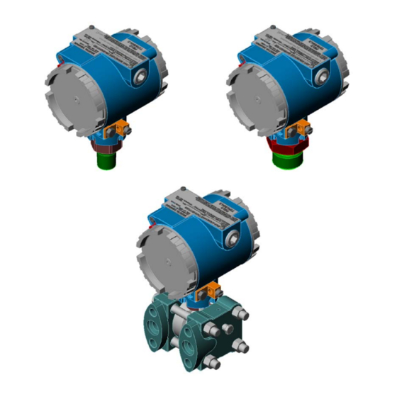
Section 1 INTRODUCTION 1.1 PRODUCT DESCRIPTION Series 2808 Transmitters convert pressure measurements into a proportional 4-20 mA or a 1 - 5 Vdc output signal that functions as the input to a controller, recorder, indicator or similar device. These Transmitters find application in the gas, water, and process industries that require accurate measurements over a wide range of environmental conditions. - Page 14 Figure 1-1 - 2808-XXB Transmitters 1-2 / Introduction 2808B...
-
Page 15: Models Approved For Hazardous Areas
1.3 MODELS APPROVED FOR HAZARDOUS AREAS Transmitter models certified for operation in hazardous areas by Underwriters Laboratories (UL) will have the appropriate logo inscribed on the instrument data plate. These models are intended for use in the following hazardous locations: Explosion-proof for Class I, Division 1, Groups C and D. - Page 16 BLANK PAGE...
-
Page 17: Product Description
Section 1A GAGE PRESSURE TRANSMITTERS Model 2808-15B & 2808-16B 1A.1 PRODUCT DESCRIPTION Gage Pressure Transmitters convert a pressure measurement into a proportional 4-20 mA or a 1-5 Vdc output signal that can be applied to the input of a controller, recorder, indicator or similar device. -
Page 18: Theory Of Operation
1A.2 THEORY OF OPERATION The Transmitter body is composed of an electronics housing and a sensor module assembly as shown in the block diagram Figure 1A-3. The electronics housing contains the amplifier circuitry and the field wiring terminals. The sensor module contains a pressure input chamber, a fluid chamber, a recessed isolation diaphragm, and a micro diaphragm that includes electronic sensing circuitry. -
Page 19: Identifying Transmitter Options
4-20 mA current flowing through the resistor provides a 1-5 Vdc input for the external device. Amplifier circuitry contains gain and offset adjustments for setting range calibration. A jumper selects the damping option. At the users option, the unit may also be converted to a three-wire 1-5 Vdc output through jumper selection. - Page 20 To rotate the Transmitter Housing, the set screw that locks the Pressure Transducer to the Transmitter Housing must be removed with a 3mm Hex Wrench. Once the Transmitter Housing has been turned to the desired position, be sure to replace and tighten the set screw (see Figure 1A-4).
- Page 21 TABLE 1A-A - MODEL NUMBER BREAKDOWN FOR GP MODELS 2808-15B - 2 2 - 1 - 1 - 0 - 1 - 0 Model Suffix | | | | | | | | | | | | | | | | A B C D E F G H Position GP TRANSMITTER W/...
- Page 22 2808-16B - 2 2 - 1- 1 - 1 - 0 - 1 - 0 Model Suffix | | | | | | | | | | | | | | | | A B C D E F G H Position GP TRANSMITTER W/FLUSH INDICATION (* = 1, 2 or 3)
- Page 23 Figure 1A-5 - Overall Dimensions - Model 2808-15B (With Neck Type Mounting Bracket) 2808B GP Transmitters / 1A-7...
- Page 24 Figure 1A-6 - Overall Dimensions - Model 2808-16B (With Neck Type Mounting Bracket) 1A-8 / GP Transmitters 2808B...
-
Page 25: Pressure Measurement Applications
1A.5 PRESSURE MEASUREMENT APPLICATIONS 2808-XXB Transmitters measure the pressure of a process medium flowing through a pipe or contained in a tank. A discussion of some basic applications follows: Figure 1A-7 - Process Pipe Mounting Figure 1A-8 - Pipe Tap Connection Liquid Application. -
Page 26: Steam Application
Figure 1A-9 - Horizontal Gas Run Figure 1A-10- Vertical Gas Run Steam Application. When measuring steam pressure, the maximum temperature of the Transmitter's electronic circuitry must be strictly observed. Temperatures above the specified limit (see Environmental Temperature under topic 2.1) will cause output errors and possibly result in damage to the transmitter. -
Page 27: Liquid Level Application
Liquid Level Application. GP Transmitters can be used to measure the head pressure of a column of liquid in an open tank. For this application, the Transmitter is connected at the bottom of the tank as shown in Figure 1A-13 (the Transmitter could also be attached to the tank through an appropriate fitting). -
Page 28: Service Checks
1A.6 SERVICE CHECKS General troubleshooting hints are listed in Table 1A-C. Some of these checks will require a digital multimeter (DMM). The DMM may be connected across the (+) and (V) terminals to measure current directly without opening the current loop. See Section 4 Service for details. TABLE 1A-C - TROUBLESHOOTING CHECKS SYMPTOM RECOMMENDED CHECK... - Page 29 Wet End Materials: Model 2808-15B: 316 SS or Hastelloy C Model 2808-16B: 316 SS Process Connections: Model 2808-15B: 1/2 in. NPT male Model 2808-16B: 1 in. NPT male Mounting Position Effect on Transmitter Accuracy: ±2.0 inH O which can be corrected by calibration TABLE 1A-D - TRANSMITTER INPUT RANGES Model 100%...
- Page 30 BLANK PAGE...
-
Page 31: Product Description
Section 1B DIFFERENTIAL PRESSURE TRANSMITTERS Models 2808-35B 1B.1 PRODUCT DESCRIPTION Model 2808-35B Differential Pressure (DP) Transmitters measure the pressure differential existing across an orifice plate or similar type device and converts it into a proportional 4- 20 mA or a 1-5 Vdc signal that can be applied to the input of a device such as a flow computer, controller, recorder, etc. - Page 32 Figure 1B-1 - Model 2808-35B Figure 1B-2 - Transmitter Assemblies 1B-2 / DP Transmitters 2808B...
-
Page 33: Identifying Transmitter Options
Figure 1B-3 - Simplified Diagram Implanted on the sensor's micro-machined surface are four strain gauge resistors connected in a bridge configuration. This circuit, which is powered by a constant current supply on the amplifier board, produces a millivolt output that is equal to the difference between the two pressure inputs. - Page 34 TABLE 1B-A - MODEL NUMBER BREAKDOWN FOR DP MODELS 2808-35B - 1 4 - 1 - 2 - 1 - 2 - 2 - 0 - 2 - 1 - 1 Model Suffix | | | | | | | | | | | | | | | | | | | | | | | | A B C D E F G H J K L M Position...
- Page 35 Figure 1B-4A - Overall Dimensions for Model 2808-35B Transmitter (With Flange Type Mounting Bracket 2808B DP Transmitters / 1B-5...
- Page 36 Figure 1B-4B - Overall Dimensions for Model 2808-35B Transmitter (With Neck Type Mounting Bracket 1B-6 / DP Transmitters 2808B...
- Page 37 Figure 1B-4C - Dimensions for Model 2808-35B Transmitter (With Manifold Adapter Option) 2808B DP Transmitters / 1B-7...
-
Page 38: Transmitter Mounting
1B.4 TRANSMITTER MOUNTING Transmitters may be mounted in any position. However, when a Transmitter leaves the factory, it is calibrated for operation in the upright position with the electronics enclosure at the top and the DP connections at the bottom as shown in Figure 1B-2. If it is installed in a different position, the Transmitter may require a slight zero adjustment. -
Page 39: Optional Process Manifold Block
front, rear or bottom of the Transmitter. Care should be taken not to damage the sensor module assembly during this procedure. Once the flange has been positioned, the bolts should be tightened in an alternating sequence to about 20-30 foot-pounds of torque. Optional Process Manifold Block. - Page 40 Figure 1B-6 - Transmitter Housing Rotation Diagram 1B-10 / DP Transmitters 2808B...
-
Page 41: Dp Measurement Applications
1B.5 DP MEASUREMENT APPLICATIONS 2808-XXB Transmitters measure the differential pressure of pressurized liquids, gases, or steam. They can also be used to measure a column of liquid in a tank or vessel. A discussion of some basic applications follows: Liquid Application. When measuring the differential of pressurized liquids, mount the DP Transmitter below the orifice plate to minimize entry of air into the Transmitter and its con-necting lines. -
Page 42: Steam Application
An on-site, zero test signal for calibration purposes can be generated by opening the bypass valve and closing both shutoff valves. Calibration information will be found in Section 3. Figure 1B-9 - Gas, Horiz, Pipe Figure 1B-10 - Gas, Vert. Pipe Steam Application. -
Page 43: Liquid Level Application
A liquid-filled line is one way to isolate the Transmitter from a steam process. As an al- ernate method, a steam trap may be installed in the connecting line. Several manufacturers offer traps for this application. Liquid Level Application. DP Transmitters can be used to measure the head pressure of a column of liquid in an open tank. -
Page 44: Service Checks
Figure 1B-15 - Closed Tank with Air Purge The purge meter (pressure regulator) maintains a pressure on the dip tube that is about 5% above the maximum pressure of a full tank. This prevents the liquid from backing up the dip tube into the HI side of the Transmitter. For this application, the liquid in the tank should not be allowed to exceed the maximum (100%) measurement level or else it may backflow into the LO side of the Transmitter. -
Page 45: Transmitter Specifications
TABLE 1B-B - TROUBLESHOOTING CHECKS SYMPTOM RECOMMENDED CHECK Low or no output: Check power supply for low dc output. Check field wiring for shorts, opens, grounds or excessive resistance. Make sure that shutoff valves in both DP lines are fully open and that any line bypass valve is fully closed. - Page 46 Lower Body Materials: Diaphragm Stainless Steel, Hastelloy-C Flange Stainless Steel, Hastelloy-C Flange Bolts Carbon Steel, Press. SS (17-4), SS (18-8) Manifold Stainless Steel, Hastelloy-C Electronics Housing: Low copper aluminum, epoxy finish, NEMA 4X rating. Mounting Position Effect on Transmitter Accuracy: ±2.0 inH O which can be corrected by calibration...
-
Page 47: Section 2 - Installation
Section 2 INSTALLATION 2.1 INSTALLATION NOTES Prior to installing the Transmitter, factors such as environmental temperature, main- tenance access, and Transmitter construction materials will require consideration. Environmental Temperature: The temperature operating ranges for the wet end and elec- tronics assemblies of the Transmitter are as follows: 1. -
Page 48: Electrical Wiring Notes
The installation of equipment in hazardous areas must comply with the National Electrical Code ANSI/NFPA-70, and ANSI/ISA S82.01, S82.02, & S82.03 standards. Transmitters certified for use in hazardous areas will have the mark of the certifying agency inscribed on the Transmitter data plate. The checklist that follows emphasizes some key points of safety with regard to installations in hazardous areas. -
Page 49: Wiring Of 4-20Ma Signal/Power Loop
Conduit Connection: The Transmitter provides a ½ inch NPT threaded female port for electrical conduit. This port can mate with threaded conduit or an appropriate threaded pipe adapter. Note: The conduit connections must be secured with no less than five threads fully engaged. In some applications, condensation could form in the conduit, and seep into the Transmit- ter electronics housing. - Page 50 * The device may be an indicator, recorder, tone modulator, etc. Connect the shield to earth ground or to a shield terminal on the device, if so equipped. Refer to Figure 3-2 and set the Jumper Block for Current Operation. Figure 2-2 - Transmitter Wired to Instrument Supply Source (4-20mA Circuit) * The device may be an indicator, recorder, tone modulator, etc.
- Page 51 * The device may be an indicator, recorder, tone modulator, etc. Connect the shield to earth ground or to a shield terminal on the device, if so equipped. Refer to Figure 3-2 and set the Jumper Block for Voltage Operation. Figure 2-4 - Transmitter Wired to Instrument Supply Source (1-5V Circuit) * The device may be an indicator, recorder, tone modulator, etc.
-
Page 52: Wiring Of 1-5V Signal/Power Loop
2.5 WIRING OF 1-5V SIGNAL/POWER LOOP The 1-5V signal/power loop can be powered in two ways, by the receiving device (controller, recorder, etc.), or by an external supply. Provide a setup similar to that shown in either Figure 2-4 or 2-5. Apply +24V across the + and - terminals of the Transmitter as shown, whether supplied by an external supply, or by the receiving device. - Page 53 Figure 2-7 - Transmitter with Digital Indicator The graph of Figure 2-8 shows the cable length in feet vs. the cable resistance of both con- ductors for wire gauges between AWG 14 and AWG 22. For cable runs less than 1000 feet, the resistance can be ignored.
- Page 54 BLANK PAGE...
-
Page 55: Section 3 - Calibration
Section 3 CALIBRATION 3.1 CALIBRATION SETUP Equipment Required: Transmitter calibration requires a laboratory bench setup with the following equipment: 1. Test source capable of generating fixed pressure values equivalent to 0%, and 100% values of transmitter’s range (URL). 2. Pressure monitor device to read test source (±.025% accuracy) 3. - Page 56 To access the fine offset (A1) and fine gain (A2) adjustment screws, loosen the screw that secures the I.D. Plate to the top of the Transmitter housing and pivot the I.D. Plate. The fine offset and gain screws are labeled A1 and A2 respectively. The calibration label that identifies A1 and A2 is affixed to the top of the Transmitter housing and will be exposed when the I.D.
- Page 57 Figure 3-2 - Calibration Adjustments 2808B Calibration / 3-3...
-
Page 58: External Check Procedure
3.3 EXTERNAL CHECK PROCEDURE The general check procedure determines the accuracy of the Transmitter at its calibrated operating range. It uses the offset (A1) and the gain (A2) adjustment screws for minor calibration corrections. Proceed as follows: 1. Provide a test setup as shown in Figure 3-1a or 3-1b depending on whether the unit has been configured for current or voltage mode. -
Page 59: Types Of Range Calibration
Coarse Span URL Range ------------ X 100% Once span has been calculated the desired switch position can be determined from Table 3- A or Table 3-B. Coarse Zero: Coarse zero adjustments are provided by switches S1:1-8. When these switches are all set to ON, the maximum zero suppression (600%) is provided; when all are set to OFF, the maximum zero elevation (600%) is provided. - Page 60 TABLE 3-A - COARSE ZERO SWITCH SETTINGS (Elevation) 3-6 / Calibration 2808B...
- Page 61 TABLE 3-B - COARSE ZERO SWITCH SETTINGS (Suppression) 2808B Calibration / 3-7...
-
Page 62: Zero-Based Calibration
Suppressed Zero Calibration: 0 psi < 1V (4-20mA) output [0 psi results in an output less than 1V (4mA)] Sample Ranges: 1 to 10 psi 10 to 60 psi 50 to 100 psi The above procedures are described in topics 3.6, 3.7, and 3.8. Select the procedure you require. -
Page 63: Zero Elevation Example
2. Calculate the desired output reading for 0 psi. For this example, 0 psi = 25% of the span from -10 to 30 psi. The output should therefore be 25% of the way from 1-5V, or 2V(8mA). Set the Dip and Rotary switches in accordance with Table 3-A. Elevated zero values are expressed as positive percentages of calibrated span. - Page 64 2. Set the Dip and Rotary switches in accordance with Table 3-B. Suppressed zero values are expressed as negative percentages of upper range limit (URL). Zero percent URL represents no suppression. If the desired percent suppression is in between values, try the next closest setting.
-
Page 65: Zero Suppression Example
3.8.1 Zero Suppression Example (see Figure 3-3 & Table 3-B) The full water tower of Figure 3-3, produces 53.5 psi of pressure due to the 125 foot head, i.e 10.7 psi plus 42.8 psi. To determine the Coarse Span Rotary Switch (SW1) setting, divide the pressure produced by the 25 feet of water in the tank by the Transmitter’s range;... - Page 66 BLANK PAGE...
-
Page 67: Section 4 - Service
Section 4 SERVICE 4.1 GENERAL Servicing should only be performed by technically competent persons skilled in the use of pneumatic and electronic test equipment and having knowledge of troubleshooting procedures. After any service procedures are completed, the Transmitter cover must be installed and properly tightened. - Page 68 Figure 4-1 - Using Internal TEST Terminals to Measure Current 4-2 / Service 2808B...
-
Page 69: Section 5 - Specifications
Section 5 SPECIFICATIONS NOTE: The specifications listed here are common to all 2808 models described in this manual. Specifications that are specific to each model are given in Sections 1A and 1B. 5.1 FUNCTIONAL SPECIFICATIONS Current Loop Mode: Supply Voltage 24.0 Vdc nominal 7.00 Vdc min. -
Page 70: Linearity
Recovery: Time to steady output after application of 24 volt supply with constant pressure is 250 ms maximum (With No Damping) Linearity: On low-range models, full vacuum can represent an appreciable percentage of URL. If, on those models, calibration contains zero elevation, non-linearity errors can be as high as +1%. -
Page 71: Humidity Limits
Humidity Limits: Specified with Transmitter electronic housing cover installed. 15-95% RH to 140 °F (60 °C) 15-50% RH to 185 °F (85 °C) EMI Effect: +1% of URL @ 10 V/M, 20 MHz to 500 MHz Meets /SAMA PMC-33-1C with Transmitter cover in place and all wiring contained in grounded conduit. - Page 72 BLANK PAGE...
-
Page 73: Special Instructions For Class I, Division 2 Hazardous Locations
Series 2808 Transmitters - Models 2808-15B, 16B & 35B Special Instructions for Class I, Division 2 Hazardous Locations 1. The Bristol Series 2808 Pressure Transmitters, Models 2808-15B, 28-0-16B & 2808-35B are listed by Underwriters Laboratories (UL) as nonincendive and are suitable for use in Class I, Division 2, Groups A, B, C and D hazardous locations or non-hazardous locations. - Page 74 BLANK PAGE...
-
Page 75: Loop Powered Indicator Option
Appendix B Issue: 03/2007 LOOP POWERED INDICATOR OPTION For Instruction Manual CI-2808B Pt. No 621498-01-7 Bristol, Inc. - Page 76 Appendix B LOOP POWERED INDICATOR OPTION PT. NO. 621498-01-7 TABLE OF CONTENTS SECTION TITLE Section 1 - INTRODUCTION INTRODUCTION ....................1 1.1.1 Features........................ 1 1.1.2 Hardware Circuit Overview ................1 1.1.3 Adjustments ......................2 1.1.4 Connectors......................2 Section 2 - INSTALLATION, OPERATION & SERVICE INSTALLATION &...
-
Page 77: Introduction
Section 1 INTRODUCTION 1.1 INTRODUCTION The loop powered indicator (LPI) option is used to provide local indication in engineering units of the measurand represented by a 4-20 mA current loop. The LPI may be installed in a Model 2808 Transmitter with the 2808 Display Cover Assembly or in a stand-alone housing. -
Page 78: Adjustments
The two-board assembly is designed for field retrofit in the 2808 pressure transmitters. 1.1.3. Adjustments Adjustment potentiometers are unnecessary in the LPI. The indicator is always scaled to 4- 20mA. The user configures the LPI in engineering units of their choice, i.e., mA, %, psi, IN H2O, bar, kg/cm2, °C, °F or Custom. -
Page 79: Section 2 - Installation, Operation & Service
Section 2 INSTALLATION, OPERATION & SERVICE 2.1 INSTALLATION & REMOVAL/REPLACEMENT OF THE LPI 2.1.1 Installation/Removal of the Loop Powered Indicator The following parts are provided for field installation of the Loop Powered Indicator option: One (1) - O-Ring, Size - 149 Two (2) - Standoffs, #4 M/F Shoulder Two (2) - Standoffs, 4-40 x .750 M/F One (1) - Meter Motherboard Ass’y. - Page 80 2. Referring to Figure 2-2, install the two (2) 4-40 x .759 Standoffs into the Model 2808 Transmitter at location A. Figure 2-1 - Transmitter Cover Assembly Removal 3. Referring to Figure 2-2, install the two (2) 4-40 x .375 Standoffs into the Model 2808 Transmitter at location B.
- Page 81 Figure 2-2 - Loop Powered Indicator Installation Diagram Appendix B Page 5 Loop Powered Indicator...
- Page 82 8. Connect the field wires to the compression-type terminals of Meter Motherboard Terminal Block TB1 (see Section 2.2 & Figure 2-5). Configure the LPI for operation (see Section 2.3.1). 9. Install the Transmitter Display Cover Assembly (with size 149 O-Ring) onto the Transmitter (see Figures 2-3 &...
-
Page 83: Field Wiring
10. To remove the LPI Option from a Model 2808 Transmitter, follow steps 7 through 9 in reverse order, removing rather than installing the item in question. 2.2 FIELD WIRING The LPI uses compression-type terminals that accommodate up to #14 AWG wire. A connection is made by inserting the bared end (1/4 inch Max.) into the Meter Motherboard Connector (TB1) clamp beneath the screw and then securing the screw. - Page 84 from configuration mode to run mode. At any point in the sequence pressing the Mode button selects the next item in the order i.e., to leave a previously configured item as is, press Mode to skip over it. When configuration is started a one-minute timer is loaded; it is reloaded whenever a Mode or Select button is pressed.
- Page 85 If the selected unit is mA or % no further configuration is allowed and configuration mode ends. For other units the following occurs. The SET LO legend appears with the minus sign blinking, and the previously con- figured digits for the Zero appear without a decimal point. Previously configured minus sign and ten-thousandths half-digit choices are cancelled, and new selections must be made.
-
Page 86: Accuracy And Decimal Point Settings
If the selected BU is Custom, no other units are affected. Upon power-up the MPU makes all display segment elements active for 5 seconds; this allows a visual check for non-functioning elements. After 5 seconds the LPI begins dis- playing values in the unit (BU) that was active before power-down. 2.3.2 Accuracy and Decimal Point Settings The LPI has a stated accuracy of ±... -
Page 87: Error Conditions
As the Mode button is pressed the display will change to the next available unit in the order shown above starting with the BU. With a BU of inH2O for example, the order would be bar, kg/cm2, mA, %, psi, then back to inH2O. 2.3.4 Error Conditions LPIs that have not been factory calibrated will alternately show a reading and UCUC (for Uncalibrated) in the display for four seconds. -
Page 88: Section 3 - Specifications
Section 3 SPECIFICATIONS 3.1 ENVIRONMENTAL SPECIFICATIONS Operating: -30°C to +70°C (-22°F to +158°F) Temperature Limits: Storage: -40°C to +85°C (-40°F to +185°F) 15% to 95% RH (Non-condensing) Humidity Limits: 10 to 500 Hz at 2g on any axis per SAMA Vibration: PMC-31-1 without damage or impairment. - Page 89 Appendix C SURGE PROTECTOR Pt. No. 388630-01-9 Transients caused by power and lightning surges can cause damage to field-mounted units. Transmitter models without meters have bipolar, differential surge protection rated at 1000 watts for 1 millisecond. Consistent surges that exceed these levels could cause a failure of the Transmitter's surge protection diode.
- Page 90 BLANK PAGE...
- Page 91 Series 2808 Transmitters Material Safety Data Sheets Material Safety Data Sheets are provided herein to comply with OSHA’s Hazard Communication Standard, 29 CFR 1910.1200. This standard must be consulted for specific requirements. Material Safety Data Sheets are provided in the order listed in Table Z-1 below. Series 2808 Transmitters TABLE Z-1 - MSDS for Instruction Manual CI-2808B...
- Page 92 BLANK PAGE...
- Page 93 DOW CORNING CORPORATION Material Safety Data Sheet Page: 1 of 7 DOW CORNING 200(R) FLUID, 100 CST. 1. IDENTIFICATION OF THE SUBSTANCE AND OF THE COMPANY 24 Hour Emergency Telephone: (989) 496-5900 Dow Corning Corporation South Saginaw Road Customer Service: (989) 496-6000 Midland, Michigan 48686 Product Disposal Information:...
- Page 94 DOW CORNING CORPORATION Material Safety Data Sheet Page: 2 of 7 DOW CORNING 200(R) FLUID, 100 CST. 4. FIRST AID MEASURES Eye: Immediately flush with water. Skin: No first aid should be needed. Inhalation: No first aid should be needed. Oral: No first aid should be needed.
- Page 95 DOW CORNING CORPORATION Material Safety Data Sheet Page: 3 of 7 DOW CORNING 200(R) FLUID, 100 CST. Containment/Clean up: Determine whether to evacuate or isolate the area according to your local emergency plan. Observe all personal protection equipment recommendations described in Sections 5 and 8.
- Page 96 DOW CORNING CORPORATION Material Safety Data Sheet Page: 4 of 7 DOW CORNING 200(R) FLUID, 100 CST. Inhalation/Suitable No respiratory protection should be needed. Respirator: Precautionary Measures: Avoid eye contact. Use reasonable care. Comments: When heated to temperatures above 150 degrees C in the presence of air, product can form formaldehyde vapors.
- Page 97 DOW CORNING CORPORATION Material Safety Data Sheet Page: 5 of 7 DOW CORNING 200(R) FLUID, 100 CST. 12. ECOLOGICAL INFORMATION Environmental Fate and Distribution Air: This product is a high molecular weight liquid polymer which has a very low vapour pressure (<1 mm Hg).
- Page 98 DOW CORNING CORPORATION Material Safety Data Sheet Page: 6 of 7 DOW CORNING 200(R) FLUID, 100 CST. RCRA Hazard Class (40 CFR 261) When a decision is made to discard this material, as received, is it classified as a hazardous waste? No State or local laws may impose additional regulatory requirements regarding disposal.
- Page 99 DOW CORNING CORPORATION Material Safety Data Sheet Page: 7 of 7 DOW CORNING 200(R) FLUID, 100 CST. Supplemental State Compliance Information California Warning: This product contains the following chemical(s) listed by the State of California under the Safe Drinking Water and Toxic Enforcement Act of 1986 (Proposition 65) as being known to cause cancer, birth defects or other reproductive harm.
- Page 100 BLANK PAGE...
- Page 101 Supplement Guide Supplement Guide S1400T-2808B S1400T-2808B -XXB -XXB Series 2808 Series 2808 Transmitters Transmitters SITE CONSIDERATIONS EQUIPMENT INSTALLATION, GROUNDING & WIRING A Guide for the Protection of Site Equipment & Personnel In the Installation of Series 2808-XXB Instrumentation Bristol, Inc. Issue: 03/2007...
- Page 102 Supplement Guide S1400T-2808B Series 2808-XXB Transmitters SITE CONSIDERATIONS FOR EQUIPMENT INSTALLATION, GROUNDING & WIRING TABLE OF CONTENTS SECTION TITLE PAGE # Section 1 - INTRODUCTION GENERAL INTRODUCTION ..................1-1 MAJOR TOPICS......................1-1 Section 2 - PROTECTION PROTECTING INSTRUMENT SYSTEMS ..............2-1 2.1.1 Quality Is Conformance To Requirements ..............
- Page 103 Supplement Guide S1400T-2808B Series 2808-XXB Transmitters SITE CONSIDERATIONS FOR EQUIPMENT INSTALLATION, GROUNDING & WIRING TABLE OF CONTENTS SECTION TITLE PAGE # Section 5 - WIRING TECHNIQUES OVERVIEW ........................5-1 INSTRUMENT WIRING....................5-1 5.2.1 Common Returns......................5-1 5.2.2 Use of Twisted Shielded Pair Wiring (with Overall Insulation) ......... 5-2 5.2.3 Grounding of Cable Shields.
-
Page 104: Section 1 - Introduction
Section 1 - Overview 1.1 INTRODUCTION This document provides information pertaining to the installation of Series 2808-XXB Transmitters; more specifically, information covering reasons, theory and techniques for protecting your personnel and equipment from electrical damage. Your instrument system affects the quality of service provided by your company and many aspects of its operational safety. -
Page 105: Section 2 - Protection
Section 2 - Protection 2.1 PROTECTING INSTRUMENT SYSTEMS Electrical instrumentation is susceptible to damage from a variety of natural and man made phenomena. In addition to wind, rain and fire, the most common types of system and equipment damaging phenomena are lightning, power faults, communication surges & noise and other electrical interference’s caused by devices such as radios, welders, switching gear, automobiles, etc. -
Page 106: Considerations For The Protection Of Personnel
2.2.1 Considerations For The Protection of Personnel Always evaluate the site environment as if your life depended on it. Make sure that you understand the physical nature of the location where you will be working. Table 2-1 provides a general guideline for evaluating an installation site. Table 2-1 - Installation Site Safety Evaluation Guide Guide Indoor or outdoor –... -
Page 107: Other Site Safety Considerations
Table 2-2 - Equipment Protection Site Safety Evaluation Guide (Continued) Guide Reference Section Are there overhead or underground power or com-munication See Section 2.3 cables in the immediate area? Is there an antenna in the immediate area? See Section 4.1.2 If pipe mounted, is a cathodic charge present on the pipe? See Section 3.4 Should the 2808 Transmitter be isolated? -
Page 108: Section 3 - Grounding & Isolation
Section 3 - Grounding & Isolation 3.1 POWER & GROUND SYSTEMS Series 2808-XXB Transmitters are similar in that they both have basically two system grounds, i.e., Chassis Gnd and Circuit Ground. Chassis Ground is galvanically isolated from Circuit Ground by 600V (ac/dc). Series 2808-XXB Transmitters have an input power range of +5 to +42 Vdc. -
Page 109: Establishing A Good Earth Ground
Electrical Housing) and a known good Earth Ground. Observe recommendations provided in topics Establishing a Good Earth Ground and Ground Wire Considerations. 3.3.1 Establishing a Good Earth Ground A common misconception of a ground is that it consists of nothing more than a metal pipe driven into the soil. -
Page 110: Soil Types
the soil may be to dry and/or salt free to a good conductor. If salt is lacking add rock salt (NaCl); if the soil is dry add calcium chloride (CaCl 3.3.1.2 Soil Types: Good Poor Damp Loam Back Fill Salty Soil or Sand Dry Soil Farm Land Sand Washed by a Lot of Rain... -
Page 111: Dry, Sandy Or Rocky Soil
Figure 3-3 - Basic Ground Bed Soil Test Setup with Additional Ground Rods If the Megger still reads more than 10 ohms, mix a generous amount of cooking salt, ice cream salt or rock salt with water and then pour about 2.5 to 5 gallons of this solution around each rod (including the test rods). -
Page 112: Ground Wire Considerations
Figure 3-5 - Poor Soil Ground Bed Construction Diagram Sandy soil, either wet or dry, may have had its soluble salts leached out by rain water, thereby reducing conductivity of the ground. High currents from lightning strikes could also melt sand and cause glass to form around the ground rod, rendering it ineffective. A buried counterpoise or copper screen is preferred for these installations along with regular applications of salt water. -
Page 113: Other Grounding Considerations
i This ground wire should be clamped or brazed to the Ground Bed Conductor (that is typically a stranded copper AWG 0000 cable installed vertically or horizontally). i The other end of the wire should be tinned with solder and either equipped with a terminal connector (for case mounting) or inserted into a case mounted Ground Lug (if supplied) (see Figure 3-6). -
Page 114: Isolating Equipment From The Pipeline
Figure 3-7 - Grounding of Thermometer Well in Gas Line 3.4 ISOLATING EQUIPMENT FROM THE PIPELINE 3.4.1 Meter Runs Without Cathodic Protection Series 2808-XXB Trandmitters may be mounted directly on the pipeline or remotely on a vertical or horizontal stand-alone two-inch stand-pipe. The Earth Ground Cable is to run between the 2808’s Chassis Ground Terminal and Earth Ground (Rod or Bed) even though the unit’s Multivariable Transducer may be grounded to the pipeline. - Page 115 i all conductive tubing that runs between the pipeline and mounting valve manifold and/or the units Multivariable Pressure Transducer i all conductive connections or tubing runs between the 3808 Transmitter and turbine any other input device that is mounted on the pipeline i any RTD and its mount/interface to the pipeline.
- Page 116 Figure 3-9 - 2808-35B MVT Remote Installation (with Cathodic Protection) Section 3 - Grounding & Isolation Page 3-9 S1400T-2808B...
-
Page 117: Section 4 - Lightning Arresters & Surge Protectors
Section 4 - Lightning Arresters & Surge Protectors 4.1 STROKES & STRIKES Lightning takes the form of a pulse that typically has a 2 µS rise and a 10 µS to 40 µS decay to a 50% level. The IEEE standard is an 8 µS by 20 µS waveform. The peak current will average 18 KA for the first impulse and about half of that for the second and third impulses. - Page 118 Thunderstorms are cloud formations that produce lightning strikes (or strokes). Across the United States there is an average of 30 thunderstorm days per year. Any given storm may produce from one to several strokes. Data on the subject indicates that for an average area within the United States there can be eight to eleven strokes to each square mile per year.
-
Page 119: Ground Propagation
4.1.2 Ground Propagation As in any medium, a dynamic pulse, like R.F., will take time to propagate. This propagation time will cause a differential step voltage to exist in time between any two ground rods that are of different radial distances from the strike. With a ground rod tied to a struck tower, the impulse will propagate its step voltage outwardly from this rod in ever-expanding circles, like a pebble thrown into a pond. -
Page 120: Use Of Lightning Arresters & Surge Protectors
i Use I/O protectors (Phone line, Radio) with a low inductance path to the ground system. i Ground the Coaxial Cable Shield (or use an impulse suppressor) at the bottom of the tower just above the tower leg ground connection. 4.2 USE OF LIGHTNING ARRESTERS &... -
Page 121: Overview
Section 5 - Wiring Techniques 5.1 OVERVIEW This section provides information pertaining to good wiring practices. Installation of Power and “Measurement & Control” wiring is discussed. Information on obscure problems, circulating ground and power loops, bad relays, etc. is presented. Good wire preparation and connection techniques along with problems to avoid are discussed. -
Page 122: Use Of Twisted Shielded Pair Wiring (With Overall Insulation)
Figure 5-1 - Field Wired Circuits With & Without A Common Return 5.2.2 Use of Twisted Shielded Pair Wiring (with Overall Insulation) For all field I/O wiring the use of twisted shielded pairs with overall insulation is highly recommended. This type of cable provides discrete insulation for each of the wires and an additional overall insulated covering that provides greater E.M.I. -
Page 123: Grounding Of Cable Shields
5.2.3 Grounding of Cable Shields DO NOT connect the cable shield to more than one ground point; it should only be grounded at one end. Cable shields that are grounded at more than one point or at both ends may have a tendency to induce circulating currents or sneak circuits that raise havoc with I/O signals. -
Page 124: High Power Conductors And Signal Wiring
5.2.7 High Power Conductors and Signal Wiring When routing wires, keep high power conductors away from signal conductors. Space wires appropriately to vent high voltage inductance. Refer to the National Electrical Code Handbook for regulatory and technical requirements. 5.2.8 Use of Proper Wire Size Series 2808 Transmitters utilize screw terminals that accommodate up to AWG 14 gauge wire. -
Page 125: Secure Wiring Connections
line as close to the modem as possible. Any unit equipped with a radio or modem must be connected to a known good earth ground via the units Ground Lug. 5.2.10 Secure Wiring Connections Make sure that all wiring connections are secure. In time wires that were once round will become flattened due to the pressure applied by screw compression type terminals and site vibrations. - Page 126 Phone: 905-362-0880 Fax: 905-362-0882 The Emerson logo is a trade mark and service mark of Emerson Electric Co. www.EmersonProcess.com/Bristol Trademarks or copyrighted products mentioned in this document are for information only, and belong to their respective companies, or trademark holders.
- Page 127 ESDS Manual S14006 4/15/92 CARE AND HANDLING PC BOARDS ESD-SENSITIVE COMPONENTS BRISTOL BABCOCK...
- Page 128 BLANK PAGE...
- Page 129 ESDS Manual S14006 4/15/92 TABLE OF CONTENTS PAGE TOOLS AND MATERIALS REQUIRED ESD-SENSITIVE COMPONENT HANDLING PROCEDURE Introduction General Rules Protecting ESD-Sensitive Components Static-Safe Field Procedure Cleaning and Lubricating Completion TOOLS AND MATERIALS REQUIRED Tools Anti-Static Field kit. It is recommended that an anti-static field kit be kept on any site where solid-state printed circuit boards and other ESD-sensitive compo- nents are handled.
-
Page 130: Esd-Sensitive Component Handling Procedure
ESDS Manual #S14006 4/15/92 Materials Inhibitor (Texwipe Gold Mist ; Chemtronics Gold Guard, or equivalent) Cleaner (Chemtronics Electro-Wash; Freon TF, or equivalent) Wiping cloth (Kimberly-Clark Kim Wipes, or equivalent) ESD-SENSITIVE COMPONENT HANDLING PROCEDURE Introduction Microelectronic devices such as PC boards, chips and other components are electro- static-sensitive. -
Page 131: General Rules
ESDS Manual S14006 4/15/92 Table 1 Typical Electrostatic Voltages Electrostatic Voltages Means of Static 10-20 Percent 65-90 Percent Generation Relative Humidity Relative Humidity Walking across carpet 35,000 1,500 Walking over vinyl floor 12,000 Worker at bench 6,000 Vinyl envelopes for work instructions 7,000 Poly bag picked up from bench 20,000... - Page 132 ESDS Manual #S14006 4/15/92 Typical Chip Removal Tool It is important to note when inserting EPROMS/PROMS, that the index notch on the PROM must be matched with the index notch on the socket. Before pushing the chip into the socket, make sure all the pins are aligned with the respective socket-holes.
-
Page 133: Protecting Esd-Sensitive Components
ESDS Manual S14006 4/15/92 CAUTION Don't place ESD-sensitive components and paperwork in the same bag. The static caused by sliding the paper into the bag could develop a charge and damage the component(s). Include a note, which describes the malfunction, in a separate bag along with each component being shipped. -
Page 134: Static-Safe Field Procedure
ESDS Manual #S14006 4/15/92 Note: If a system checker is not available, use an ohmmeter connected to the cable ends to measure its resistance. The ohmmeter reading should be 1 megohm +/- 15%. Be sure that the calibration date of the ohmmeter has not expired. If the ohmmeter reading exceeds 1 megohm by +/- 15%, replace the ground cord with a new one. - Page 135 ESDS Manual S14006 4/15/92 The components can now be handled following the general rules as described in the instruction manual for the component. Place the component in a static-shielding bag before the ground cord is disconnected. This assures protection from electrostatic charge in case the work surface is located beyond the reach of the extended ground cord.
-
Page 136: Cleaning And Lubricating
ESDS Manual #S14006 4/15/92 If a component is to undergo on-site testing, it may be safely placed on the grounded work surface for that purpose. (10) After all component work is accomplished, remove the wrist straps and ground wire and place in the pouch of the work surface for future use. Cleaning And Lubricating The following procedure should be performed periodically for all PC boards and when a PC board is being replaced. - Page 137 ESDS Manual S14006 4/15/92 Clean PC board connectors as follows: Review the static-safe field procedure detailed earlier. Following the ESD-sensitive component handling procedures, remove the connectors from the boards and remove the PC boards from their holders. Use cleaner to remove excessive dust build-up from comb connectors and other connectors.
-
Page 138: Completion
ESDS Manual #S14006 4/15/92 Spray the connector liberally to flush out any contaminants. Remove any excess spray by shaking the connector or wiping with either a toothbrush, or a lint-free wiping cloth. Completion Replace any parts that were removed. Make sure that the component cover is secure. Return the system to normal operation. - Page 139 BLANK PAGE...
- Page 140 Phone: 905-362-0880 Fax: 905-362-0882 TeleFlow™ is a trademark of Bristol, Inc. The Emerson logo is a trade mark and service www.EmersonProcess.com/Bristol mark of Emerson Electric Co. Other trademarks or copyrighted products mentioned in this document are for information only, and belong to their respective companies, or Emerson Process Management trademark holders.
Need help?
Do you have a question about the Bristol 2808 Series and is the answer not in the manual?
Questions and answers