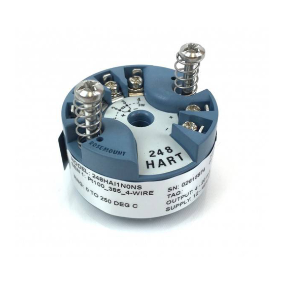
Emerson Rosemount 248 Quick Start Manual
Head mount temperature transmitter
Hide thumbs
Also See for Rosemount 248:
- Reference manual (92 pages) ,
- Quick start manual (32 pages) ,
- Quick start manual (28 pages)

Related Manuals for Emerson Rosemount 248


Summary of Contents for Emerson Rosemount 248
- Page 1 Quick Start Guide 00825-0200-4825, Rev EA February 2021 ™ Rosemount 248 Head Mount Temperature Transmitter...
-
Page 2: Table Of Contents
Quick Start Guide February 2021 Contents About this guide...........................3 Configuration..........................5 Mount the transmitter........................7 Connect the wiring........................11 Perform a loop test........................16 Certified installations......................... 17 Product certifications......................... 18... -
Page 3: About This Guide
February 2021 Quick Start Guide About this guide This guide provides basic guidelines to install the Rosemount 248 Head Mount Temperature Transmitter. It does not provide instructions for detailed configuration, diagnostics, maintenance, service, troubleshooting, or installations. Refer to the Rosemount 248 Temperature Transmitter Reference Manual for more instruction. - Page 4 Quick Start Guide February 2021 WARNING Physical access Unauthorized personnel may potentially cause significant damage to and/or misconfiguration of end users’ equipment. This could be intentional or unintentional and needs to be protected against. Physical security is an important part of any security program and fundamental to protecting your system.
-
Page 5: Configuration
Bench calibration There are three ways to configure the transmitter: • Field Communicator • Rosemount 248 PC Programming Kit • Custom at the factory using the C1 option code Refer to the Rosemount 248 Reference Manual and the Field Communicator User Guide for more information. - Page 6 Quick Start Guide February 2021 Verify transmitter configuration To verify operation using a Field Communicator, refer to the Rosemount 248 Reference Manual for more detailed description. ® Install PC programmer kit (HART 5 only) Procedure 1. Install all necessary software for PC configuration: a) Install the Rosemount 248C software 1.
-
Page 7: Mount The Transmitter
February 2021 Quick Start Guide Mount the transmitter Overview Mount the transmitter at a high point in the conduit run to prevent moisture from draining into the transmitter housing. Typical European and Asia Pacific installation Head mount transmitter with DIN plate style sensor Procedure 1. - Page 8 Quick Start Guide February 2021 Figure 3-1: Typical European and Asia Pacific Installation A. Transmitter mounting screws B. Rosemount 248 Transmitter C. Integral mount sensor with flying leads D. Connection head E. Extension F. Thermowell Typical North and South American installation...
- Page 9 February 2021 Quick Start Guide Note Enclosure covers must be fully engaged to meet explosion-proof requirements. Figure 3-2: Typical North and South American Installation A. Threaded thermowell B. Standard extension C. Threaded style sensor D. Universal head E. Conduit entry Mounting to a DIN rail Procedure •...
- Page 10 Quick Start Guide February 2021 3.4.1 Rail mount transmitter with remote mount sensor The least complicated assembly uses: • a remote mounted transmitter • an integral mount sensor with terminal block • an integral style connection head • a standard extension •...
-
Page 11: Connect The Wiring
February 2021 Quick Start Guide Connect the wiring Diagrams and power • Wiring diagrams are located on the top label of the transmitter. • An external power supply is required to operate the transmitter. • The power required across the transmitter power terminals is 12 to 42.4 Vdc (the power terminals are rated to 42.4 Vdc). - Page 12 Quick Start Guide February 2021 4.1.3 Ground the transmitter: Option 1 Use this method for grounded housing. Procedure 1. Connect sensor wiring shield to the transmitter housing. 2. Ensure the sensor shield is electrically isolated from surrounding fixtures that may be grounded. 3.
- Page 13 February 2021 Quick Start Guide Figure 4-3: Option 2: Grounded Housing A. Sensor wires B. Transmitters C. DCS host system D. Shield ground point 4.1.5 Ground the transmitter: Option 3 Use this method for grounded or ungrounded housing. Procedure 1. Ground sensor wiring shield at the sensor, if possible. 2.
- Page 14 Quick Start Guide February 2021 Figure 4-4: Option 3: Grounded or Ungrounded Housing A. Sensor wires B. Transmitters C. DCS host system D. Shield ground point 4.1.6 Ground the transmitter: Option 4 Use this method for grounded thermocouple inputs. Procedure 1.
- Page 15 February 2021 Quick Start Guide Figure 4-5: Option 4: Grounded Thermocouple Inputs A. Sensor wires B. Transmitters C. DCS host system D. Shield ground point Quick Start Guide...
-
Page 16: Perform A Loop Test
Quick Start Guide February 2021 Perform a loop test Overview The loop test command verifies transmitter output, loop integrity, and operation of any recorders or similar devices installed in the loop. Note This is not available with the Rosemount 248C Configuration Interface. Initiate loop test Procedure 1. -
Page 17: Certified Installations
February 2021 Quick Start Guide Certified installations For Safety Certified installations, refer to the Rosemount 248 Reference Manual. You can access this manual electronically at Emerson.com/ Rosemount or by contacting an Emerson representative. Quick Start Guide... -
Page 18: Product Certifications
A copy of the EU Declaration of Conformity can be found at the end of the Quick Start Guide. The most recent revision of the EU Declaration of Conformity can be found at Emerson.com/Rosemount. Ordinary location certification As standard, the device has been examined and tested to determine that the... - Page 19 February 2021 Quick Start Guide Canada 7.5.1 I6 Canada Intrinsically Safe Certificate 1091070 Standards CAN/CSA C22.2 No. 0-10, CSA Std. C22.2 No. 25-1966, CAN/CSA C22.2 No. 94-M91, CAN/CSA C22.2 No. 157-92, CSA C22.2 No. 213-M1987, CAN/CSA C22.2 No. 60079-11:14, C22.2 No 60529-05 Markings IS CL I, DIV 1 GP A, B, C, D when installed per Rosemount drawing 00248-1056;...
- Page 20 Quick Start Guide February 2021 4. Flameproof joints are not intended for repair. 5. A suitable certified Ex d or Ex tb enclosure is required to be connected to temperature probes with Enclosure option "N". 6. Care shall be taken by the end user to ensure that the external surface temperature on the equipment and the neck of DIN Style Sensor probe does not exceed 266 °F (130 °C).
- Page 21 February 2021 Quick Start Guide Special Condition for Safe Use (X): The equipment, if supplied without an enclosure, must be installed in a suitably certified enclosure such that it is afforded a degree of protection of at least IP54 in accordance with IEC 60529 and EN 60079-15 and be located in an area of pollution degree 2 or better as defined in IEC 60664-1.
- Page 22 Quick Start Guide February 2021 Specific Conditions of Safe Use (X): 1. See certificate for ambient temperature range. 2. The non-metallic label may store an electrostatic charge and become a source of ignition in Group III environments. 3. Guard the LCD display cover against impact energies greater than four joules.
- Page 23 February 2021 Quick Start Guide 7.7.4 NG IECEx Zone 2 - without enclosure Certificate IECEx BAS 18.0063X Standards IEC 60079-0:2017, IEC 60079-15:2010 Markings Ex nA IIC T5/T6 Gc; T5(-60 °C ≤ T ≤ +80 °C), T6(-60 °C ≤ T ≤ +60 °C) Special Condition for Safe Use (X): The equipment, if supplied without an enclosure, must be installed in a...
- Page 24 Quick Start Guide February 2021 7.8.2 I2 Intrinsic Safety Certificate UL-BR 19.0202X Standards ABNT NBR IEC 60079-0:2013, ABNT NBR IEC 60079-11:2013 Markings Ex ia IIC T5 Ga (-60 °C ≤ T ≤ +80 °C) Ex ia IIC T6 Ga (-60 °C ≤ T ≤...
- Page 25 February 2021 Quick Start Guide 证书编号后缀“X”表明产品具有安全使用特殊条件:涉及隔爆接合面的 维修须联系产品制造商 产品使用注意事项 • Table 7-1: 产品使用环境温度与温度组别的关系为 温度组别 环境温度 T6~T1 -50 °C ≤ T ≤ +40 °C T5~T1 -50 °C ≤ T ≤ +60 °C 2. 产品外壳设有接地端子,用户在使用时应可靠接地 3. 安装现场应不存在对产品外壳有腐蚀作用的有害气体 4. 现场安装时,电缆引入口须选用国家指定的防爆检验机构按检 验认可、具有 Ex dⅡC 防爆等级的电缆引入装置或堵封件,冗余 电缆引入口须用堵封件有效密封...
- Page 26 Quick Start Guide February 2021 Markings Ex nA IIC T5/T6 Gc; T6(-60 °C ≤ T ≤ +60 °C) T5(-60 °C ≤ ≤ +80 °C); Vmax = 42.4 Vdc Special Condition for Safe Use (X): See certificate for special conditions 7.10 7.10.1 EM Technical Regulation Customs Union (EAC) Flameproof Markings 1Ex d IIC T6…T1 Gb X, T6(-50 °C ≤...
- Page 27 February 2021 Quick Start Guide 7.12 Combinations Combination of E1, I1, N1, and ND Combination of E5 and I5 Combination of I6 and Canada Explosionproof Combination of E7, I7, and N7 Combination of EM and IM with Dust Quick Start Guide...
- Page 28 Capacitance C 0 nF 1.54 nF Inductance L 0 mH 0 µH 7.14 Additional certification (Rosemount 248 Head Mount only) SBV Bureau Veritas (BV) Type Approval Certificate: 26325 Requirements: Bureau Veritas Rules for the Classification of Steel Ships Application: Class notations: AUT-UMS, AUT-CCS, AUT-PORT and AUT- IMS;...
- Page 29 February 2021 Quick Start Guide 7.15 Declaration of Conformity Quick Start Guide...
- Page 30 Quick Start Guide February 2021...
- Page 31 February 2021 Quick Start Guide Quick Start Guide...
- Page 32 Quick Start Guide February 2021 7.16 China RoHS...
- Page 33 February 2021 Quick Start Guide Quick Start Guide...
- Page 34 Quick Start Guide February 2021...
- Page 35 February 2021 Quick Start Guide Quick Start Guide...
- Page 36 The Emerson logo is a Twitter.com/Rosemount_News trademark and service mark of Emerson Electric Facebook.com/Rosemount Co. Rosemount is a mark of one of the Emerson Youtube.com/user/ family of companies. All other marks are the RosemountMeasurement property of their respective owners.
Need help?
Do you have a question about the Rosemount 248 and is the answer not in the manual?
Questions and answers