Sign In
Upload
Manuals
Brands
Emerson Manuals
Transmitter
Bristol 2808 Series
Emerson Bristol 2808 Series Manuals
Manuals and User Guides for Emerson Bristol 2808 Series. We have
1
Emerson Bristol 2808 Series manual available for free PDF download: Instruction Manual
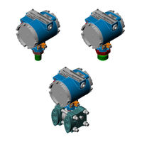
Emerson Bristol 2808 Series Instruction Manual (140 pages)
Gage Pressure Transmitter
Brand:
Emerson
| Category:
Transmitter
| Size: 8.72 MB
Table of Contents
CI-2808B Series 2808 Pressure Transmitters Model 2808-15B, 16B & 35B
9
Table of Contents
9
Product Description
13
Transmitter Features
13
Section 1 - INTRODUCTION
13
Models Approved for Hazardous Areas
15
Using this Manual
15
Product Description
17
Theory of Operation
18
Optional Mounting Bracket
19
4.1 Transmitter Housing Rotation
19
Transmitter Mounting
19
Connection-Supported Mounting
19
Identifying Transmitter Options
19
Pressure Measurement Applications
25
Liquid Application
25
Gas Application
25
Steam Application
26
Liquid Level Application
27
Gp Transmitter Specifications
28
Service Checks
28
Theory of Operation
31
Product Description
31
Identifying Transmitter Options
33
Transmitter Mounting
38
Standard Process Flange
38
Optional Process Manifold Block
39
Vent Plug
39
4.1 Transmitter Housing Rotation
39
Gas Application
41
Dp Measurement Applications
41
Liquid Application
41
Steam Application
42
Liquid Level Application
43
Service Checks
44
Transmitter Specifications
45
Section 2 - INSTALLATION
47
Installation Notes
47
Installation in Hazardous Areas
47
Electrical Wiring Notes
48
WIRING of 4-20Ma SIGNAL/POWER LOOP
49
Wiring of 1-5V Signal/Power Loop
52
Effects of Lead & Load Resistance & Supply Voltage
52
Section 3 - CALIBRATION
55
Calibration Setup
55
Access to Adjustments
55
External Check Procedure
58
Calibration Adjustments
58
Types of Range Calibration
59
Elevated Zero Calibration
62
Zero-Based Calibration
62
Zero Elevation Example
63
Suppressed Zero Calibration
63
Zero Suppression Example
65
Selectable Damping
65
Section 4 - SERVICE
67
General
67
Troubleshooting
67
Factory Repairs
67
Calibration Adjustments
69
Response Time & Damping
69
Section 5 - SPECIFICATIONS
69
Voltage Mode
69
Current Loop Mode
69
Functional Specifications
69
Linearity
70
Performance Specification
70
Accuracy
70
Resolution
70
Long Term Stability
70
Ambient Temperature Effect
70
Power Supply Effect
70
Ripple and Noise
70
Environmental Specification
70
Temperature Limits
70
Electrical Connections
71
Fill Media
71
Electronics Housing
71
EMI Effect
71
Physical Specifications
71
Humidity Limits
71
Vibration Effect
71
Surge Protection
71
Special Instructions for Class I, Division 2 Hazardous Locations
73
Loop Powered Indicator Option
75
Appendix B Loop Powered Indicator Option Pt. No. 621498-01-7
76
Features
77
Hardware Circuit Overview
77
Introduction
77
Adjustments
78
Connectors
78
Installation & Removal/Replacement of the Lpi
79
Installation/Removal of the Loop Powered Indicator
79
Section 2 - INSTALLATION, OPERATION & SERVICE
79
Configuring the Loop Powered Indicator
83
Field Wiring
83
Operational Details
83
Accuracy and Decimal Point Settings
86
Displaying Current Using the LPI
86
Conversion and Display Error Conditions
87
Error Conditions
87
Service
87
Environmental Specifications
88
Section 3 - SPECIFICATIONS
88
Supplement Guide S1400T-2808B Series 2808-Xxb Transmitters Site Considerations for Equipment Installation, Grounding & Wiring
102
Major Topics
104
Section 1 - INTRODUCTION
104
Protecting Equipment & Personnel
105
Protecting Instrument Systems
105
Quality Is Conformance to Requirements
105
Section 2 - PROTECTION
105
Considerations for the Protection of Equipment
106
Considerations for the Protection of Personnel
106
Other Site Safety Considerations
107
Earth Ground Connections
108
Importance of Good Grounds
108
Power & Ground Systems
108
Section 3 - GROUNDING & ISOLATION
108
Establishing a Good Earth Ground
109
Soil Conditions
109
Soil Types
110
Dry, Sandy or Rocky Soil
111
Ground Wire Considerations
112
Other Grounding Considerations
113
Isolating Equipment from the Pipeline
114
Meter Runs with Cathodic Protection
114
Meter Runs Without Cathodic Protection
114
Chance of Being Struck by Lightning
117
Section 4 - LIGHTNING ARRESTERS & SURGE PROTECTORS
117
Strokes & Strikes
117
Ground Propagation
119
Impulse Protection Summary
119
Tying It All Together
119
Use of Lightning Arresters & Surge Protectors
120
Common Returns
121
Instrument Wiring
121
Overview
121
Use of Twisted Shielded Pair Wiring (with Overall Insulation)
122
Earth Ground Wires
123
Grounding of Cable Shields
123
Use of Known Good Earth Grounds
123
Working Neatly & Professionally
123
High Power Conductors and Signal Wiring
124
Lightning Arresters & Surge Protectors
124
Use of Proper Wire Size
124
Secure Wiring Connections
125
Esd-Sensitive Component Handling Procedure
130
Introduction
130
General Rules
131
Protecting ESD-Sensitive Components
133
Static-Safe Field Procedure
134
Cleaning and Lubricating
136
Completion
138
Advertisement
Advertisement
Related Products
Emerson Bristol 2808-15B
Emerson Bristol 2808-16B
Emerson Bristol 2808-35B
Emerson MICRO MOTION 2700
Emerson Rosemount 248
Emerson Micro Motion 2750
Emerson Rosemount 2051G
Emerson Micro Motion 2400S DN
Emerson Rosemount 2051C
Emerson Rosemount 2051T
Emerson Categories
Controller
Control Unit
Transmitter
Measuring Instruments
Fan
More Emerson Manuals
Login
Sign In
OR
Sign in with Facebook
Sign in with Google
Upload manual
Upload from disk
Upload from URL