Table of Contents

Summary of Contents for Pulsar MSRK 3512
- Page 1 MSRK-13,8V/3,5A MSRK 3512 v.1.1 Switching power supply module (buffer), with the AC absencje indication output and undervoltage bartery protection UVP. Edition: 2 from the 23 June 2010 Supercedes edition: 1 from the 15 December 2008...
-
Page 2: Table Of Contents
Features of the power supply unit: 13.8 VDC uninterruptible power supply AW output of power supply unit failure, tripped • • Controlling of the battery charging and • maintaining short-circuit (SCP) • Protecting the battery against excessive overload (OLP) • •... -
Page 3: Block Diagram
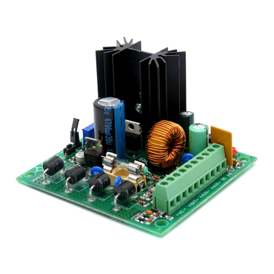
1.2. Block diagram (fig.1). Fig.1. Block diagram of the PSU module . 1.3. Description of elements and connection links of the PSU module (tab.1, tab.2, fig.2). Table 1. Element no. Element description [fig.2] START pushbutton (power activation without AC supply) JP-B, jumper - configuration of UVP battery protection function JP-B= protection function (disconnection) of the battery off... -
Page 4: Technical Parameters
Table 2. Description of power-supply unit outputs ~AC~ AC supply input (18V÷22V AC, see transformer selection) +BAT DC supply output of the battery -BAT (+BAT= red, -BAT=black) +AUX DC supply output -AUX (+AUX= +U, -AUX=GND) Technical output of AC absence – OC type level hi-Z = status: AC supplied level L = status: AC failure Technical output of power supply operation status (regulator) OC - type... -
Page 5: Installation
Table 3. Supply voltage AC: 18 V÷ 22 V, 50Hz, 4.3A max. DC: 20 V÷ 30 V, Transformer 80VA (eg. AWT 250, AWT 868) PSU module power P Output voltage 11,0 V÷13,8 V DC – buffer operation 10,0 V÷13,8 V DC – battery assisted operation Output voltage setting, escalation and keeping 120ms/50ms/15ms @Inom., Uac=min. -
Page 6: Installation Procedure
Prior to entering for the installation, the balance of load should be drawn up. Pending the normal operation, the sum of currents consumed by the consumers may not exceed I=3,5A, including baterry charging current I As the PSU module is designed for constant operation, it is not equipped with supply isolator, the proper overload protection in the supply circuit should be ensured. -
Page 7: Technical Output
3. PSU module operation indication. 3.1 Optical indication. The PSU module is equipped with three diodes indicating operation status: AC, LB, AUX. AC- red diode: under normal status (AC supply) the diode is permanently illuminated. The absence of AC • supply is indicated by the AC diode going off. - Page 8 GENERAL WARRANTY CONDITIONS 1. Pulsar K. Bogusz Sp.j. (manufacturer) grants a two-year quality warranty for the equipment, starting from the date of purchase placed on the purchase order.


Need help?
Do you have a question about the MSRK 3512 and is the answer not in the manual?
Questions and answers