
Related Manuals for Pulsar AWZ 201


Summary of Contents for Pulsar AWZ 201
- Page 1 PSU-B-13,8V/L-2A/1/EL-TR-17Ah/MC AWZ 201 v.1.0 Linear, buffer type power supply Release: 1 dated 12.10.2011 Supersedes the release: ………...
- Page 2 TABLE OF CONTENTS: 1. Technical description 2. Installation 3. Handling and operation 4. Maintenance 1. Technical description. The buffer power pack is dedicated for uninterrupted power supply for the equipment requiring the stabilized voltage 12V DC (±15%). The linear stabilizing system applied in the equipment delivers the voltage with lower level of noise and shorter response time for the interference as is the case where a pulse stabilizer is applied.
- Page 3 Technical parameters Power supply voltage 230V AC, 50 Hz (-15%/+10%) Transformer TR 50 VA Output voltage Uout *12.8 V ÷ 13.8 V DC 13.8 V DC – rated 13.4 V DC @ 2A Output current Iout Imax – 2A (const.) Power 28 W of supply power –...
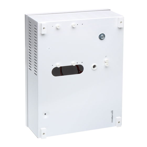
- Page 4 Figure 3. General view of the power pack.
- Page 5 ~AC~ joint +OUT + Vcc output fuse in transformer circuit -OUT - GND output Battery outputs Sabotage prevention switch Red diode TAMPER contacts – NC optical signalling Tab. 3. Description of the output joint. Green diode optical signalling Outputs Joint (Tab. 3) Voltage adjustment 230 –...
- Page 6 4. Connect the leads of the consumers to joints OUT + and - of the joint box on the power pack board [6]. (Optionally connect the MZN1 module between +OUT- and load). 5. Activate the 230 V AC power supply and insert the power network fuse protecting the transformer primary circuit [9].
- Page 7 3.3. Procedures in the case of power pack overloading. The power pack is equipped with the protection of the output stage with the application of the PTC polymer fuse. When the power pack is loaded with current exceeding 2A (110% ÷150% P) , the automatic disconnection of the output voltage takes place which is signalled by the green diode going off.
- Page 8 GENERAL WARRANTY CONDITIONS Pulsar K. Bogusz Sp.j. (manufacturer) grants a two-year quality warranty for the equipment, starting from the date of purchase placed on the purchase order. Should such purchase order be missing when the claim is submitted, the three-year guarantee period is counted from the date of the manufacturing of the device.
Need help?
Do you have a question about the AWZ 201 and is the answer not in the manual?
Questions and answers