
Related Manuals for Kramer VCO-1


Summary of Contents for Kramer VCO-1
- Page 1 USER MANUAL MODELS: VCO-1, VCO-8, VCO-16 Video Content Overlay Solution P/N: 2900-300592 Rev 1 www.kramerAV.com...
-
Page 4: Table Of Contents
Kramer Protocol 3000 Syntax 10.3 Protocol 3000 Commands Figures Figure 1: VCO-1 Front and Rear Panels Figure 2: VCO-8 and VCO-16 Front Panels Figure 3: VCO-8 and VCO-16 Rear Panels Figure 4: Connecting the VCO-8 / VCO-16 Figure 5: Connecting the VCO-1... - Page 5 Figure 68: New Template Added Figure 69: Setting the Movement and Transparency – the Program Editor Figure 70: Scheduling Tab Figure 71: Scheduling – Adding an Event Figure 72: Scheduling – Adding Overlays to the Event VCO-1, VCO-8, VCO-16 - Contents...
- Page 6 Figure 77: DHCP Mode DIP-Switch Setup Figure 78: Local Area Connection Properties Window Figure 79: Internet Protocol Version 4 Properties Window Figure 80: Internet Protocol Version 6 Properties Window Figure 81: Internet Protocol Properties Window VCO-1, VCO-8, VCO-16 – Contents...
-
Page 7: Introduction
Room Connectivity; GROUP 10: Accessories and Rack Adapters; GROUP 11: Sierra Video Products; GROUP 12: Digital Signage; GROUP 13: Audio; and GROUP 14: Collaboration. Congratulations on purchasing your Kramer VCO-1, VCO-8, VCO-16 Video Content Overlay Solution. This product, which incorporates HDMI™ technology, is ideal for: •... -
Page 8: Getting Started
Avoid interference from neighbouring electrical appliances that may adversely influence signal quality • Position your Kramer VCO-1, VCO-8, VCO-16 away from moisture, excessive sunlight and dust This equipment is to be used only inside a building. It may only be connected to other equipment that is installed inside a building. -
Page 9: Safety Instructions
Kramer Electronics has made arrangements with the European Advanced Recycling Network (EARN) and will cover any costs of treatment, recycling and recovery of waste Kramer Electronics branded equipment on arrival at the EARN facility. For details of Kramer’s recycling arrangements in your particular country go to our recycling pages at www.kramerav.com/support/recycling/. -
Page 10: Overview
1, 5, 8, or 16 and optionally to any number of displays over standard HDMI in full HD resolution (1080p60 or 1920x1200). Simply connect the Kramer VCO to each display with a single HDMI cable, choose any standard graphics file to be overlaid (such as a reminder that the bar will close at 11:00pm), and that’s all. - Page 11 VCO-8 and VCO-16 are housed in a 19” 1U rack mountable enclosure with rack “ears”. They use a 100-240 VAC universal switching power supply. VCO-1 is housed in a compact TOOLS size. Three units can be rack-mounted side by side in a 1U rack space with an optional RK-3T rack adapter tool.
-
Page 12: Defining The Video Content Overlay Solution
Defining the Video Content Overlay Solution This section defines the VCO-1, VCO-8 and VCO-16. Figure 1: VCO-1 Front and Rear Panels Feature Function IP ADDRESS DIP- For setting the last number in the machine LAN IPv4 address (see Switches Section 8.1.1) -
Page 13: Figure 2: Vco-8 And Vco-16 Front Panels
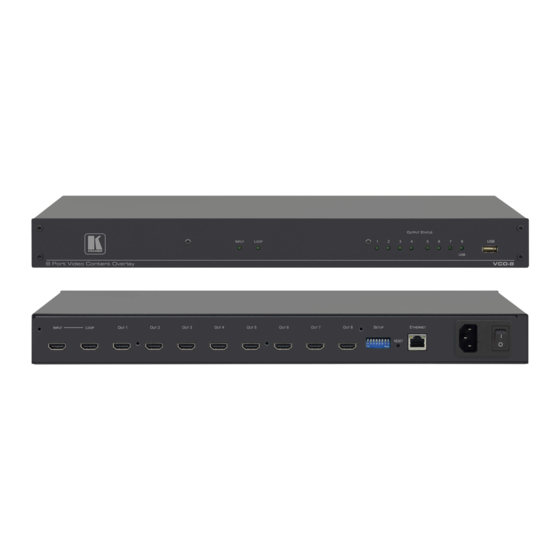
Figure 2: VCO-8 and VCO-16 Front Panels Feature Function INPUT LED Lights when an input signal is active; flashes slowly when no input signal is detected LOOP LED Lights on the looped device when a looped signal is in use OUTPUT STATUS LEDS Lights when an output signal is active USB CONNECTOR... -
Page 14: Figure 3: Vco-8 And Vco-16 Rear Panels
Figure 3: VCO-8 and VCO-16 Rear Panels Feature Function INPUT HDMI Connector Connect to the source LOOP HDMI Connector Connect to a machine to daisy chain additional displays OUT HDMI Connector Connect to the displays from 1 to 8 (VCO-8); from 1 to 16 (VCO-16) SETUP DIP-Switches For setting the Last number in the machine LAN IPv4 address (see Section... -
Page 15: Installing The Vco-8 And Vco-16 In A Rack
Installing the VCO-8 and VCO-16 in a Rack This section provides instructions for rack mounting the unit. VCO-1, VCO-8, VCO-16 - Installing the VCO-8 and VCO-16 in a Rack... - Page 16 Always switch off the power to each device before connecting it to your VCO-1, VCO-8, VCO-16. After connecting your VCO-1, VCO-8, VCO-16, connect its power and then switch on the power to each device. You do not have to connect all the outputs, connect only those that are required.
-
Page 17: Connecting The Vco-1, Vco-8, Vco-16
Figure 4: Connecting the VCO-8 / VCO-16 VCO-1, VCO-8, VCO-16 - Connecting the VCO-1, VCO-8, VCO-16... -
Page 18: Connecting The Vco-8 / Vco-16
Connecting the VCO-1 To connect the VCO-1 as illustrated in the example in Figure 1. Connect an HDMI source (for example, a media player) to the HDMI IN connector. Alternatively, you can connect the DVI connector on the DVD player to the HDMI connector on the VCO-1 via a DVI-HDMI adapter. -
Page 19: Looping The Vco-8 And Vco-16
3. On the second VCO-16 unit, connect the OUT HDMI connectors to acceptors (for example, LCD displays) In the Kramer VCO Setup App, each device in the daisy chain has a separate IP address and each of the 32 outputs is given a unique name and can be set with its own specific overlay. -
Page 20: Figure 6: A Set Of 2 Looped Vco-16 Units
Figure 6: A Set of 2 Looped VCO-16 Units VCO-1, VCO-8, VCO-16 - Looping the VCO-8 and VCO-16... -
Page 21: Using The Kramer Vco Setup Application
Using the Kramer VCO Setup Application Use the Kramer VCO Setup App to manage and send an overlay to each output. The VCO Setup App allows you to take a template which can include one or more graphic files and a playback program, modify the program and settings if needed, and load the resulting overlay onto specific device outputs. -
Page 22: Figure 7: Installing The Vco Setup App - Warning
3. Click Run. The following window appears: Figure 8: Installing the VCO Setup App – Setup Application Description 4. Click Next>. Figure 9: Installing the VCO Setup App – Legal info VCO-1, VCO-8, VCO-16 - Using the Kramer VCO Setup Application... -
Page 23: Figure 10: Installing The Vco Setup App - Setting The Destination Folder
6. Check the destination folder and change if needed then click Install. The software is installed: Figure 11: Installing the VCO Setup App– Installing the Software Figure 12: Installing the VCO Setup App – Installation is Complete VCO-1, VCO-8, VCO-16 - Using the Kramer VCO Setup Application... -
Page 24: Figure 13: Installing The Vco Setup App - The Setup & About Tab
(see Section 7.2) • Overlays – Create templates and overlays (see Section 7.3) • Scheduling – Schedule the overlays per output (see Section 7.4) VCO-1, VCO-8, VCO-16 - Using the Kramer VCO Setup Application... -
Page 25: Setup & About
1. Click the Setup & About tab. The Setup & About tab appears: Figure 14: Setup & About Tab 2. Select the application language from the dropdown box. Figure 15: Setup & About – Selecting the Language VCO-1, VCO-8, VCO-16 - Using the Kramer VCO Setup Application... -
Page 26: Figure 16: Welcome To Device Wizard
The Device Wizard opens. The window on the left shows the list of the devices installed (empty in the example in Figure 16). Figure 16: Welcome to Device Wizard 2. Click Add New Device> to add a new device to the list. VCO-1, VCO-8, VCO-16 - Using the Kramer VCO Setup Application... -
Page 27: Figure 17: Device Wizard
Manually, by entering the IP address (if you have the IP address of the device), see Section 7.2.3 Automatically, by scanning for IP addresses up to a certain address, Section 7.2.4. VCO-1, VCO-8, VCO-16 - Using the Kramer VCO Setup Application... -
Page 28: Figure 18: Device Wizard - Add Device Manually
To manually add a new device to the list: 1. Check the manual option: Figure 18: Device Wizard – Add Device Manually 2. Click Next>. Figure 19: Device Wizard – Selecting a Device VCO-1, VCO-8, VCO-16 - Using the Kramer VCO Setup Application... -
Page 29: Figure 20: Device Wizard - Device Selected
The window shows a photo and a short description of the selected device. 4. Click Next>. This window lets you set the IP Address. Figure 21: Device Wizard – Setting the IP Address VCO-1, VCO-8, VCO-16 - Using the Kramer VCO Setup Application... -
Page 30: Figure 22: Device Wizard - Setting The Lower Number Of The Ip Address
7. To change the other parts of the IP address, check the change address box and click Next>. If you do not want to change the other parts of the IP address, keep that box unchecked and click Next>. VCO-1, VCO-8, VCO-16 - Using the Kramer VCO Setup Application... -
Page 31: Figure 23: Device Wizard - Setting The Higher Parts Of The Ip Address
Figure 23: Device Wizard – Setting the Higher parts of the IP Address 9. Connect the device as instructed and click Next>. The following window appears: Figure 24: Device Wizard – Changing the IP Address VCO-1, VCO-8, VCO-16 - Using the Kramer VCO Setup Application... -
Page 32: Figure 25: Device Wizard - Changing The Higher Parts Of The Ip Address
10. Change the number, for example, to 192.168.2.39. Figure 25: Device Wizard – Changing the Higher Parts of the IP Address 11. Click Next>. The following message appears: Figure 26: Changing the IP Address Message VCO-1, VCO-8, VCO-16 - Using the Kramer VCO Setup Application... -
Page 33: Figure 27: Device Wizard - Changing The Ip Address Higher Parts
The application changes the IP address on the machine while it’s connected. 13. Click Test! to test the connection or just click Next>. Figure 28: Device Wizard – Testing the IP Address Change VCO-1, VCO-8, VCO-16 - Using the Kramer VCO Setup Application... -
Page 34: Figure 29: Device Wizard Setting The Recommended Name
039 and each output is numbered in sequence: 03901, 03902, and so on). You can also add a short description to this particular device: Figure 30: Device Wizard – Set the Device Name VCO-1, VCO-8, VCO-16 - Using the Kramer VCO Setup Application... -
Page 35: Figure 31: Device Wizard - Device Installed
— below the list. This page shows the properties of the selected device and lets you change each individual output name. You can test the connection to the machine at this point. VCO-1, VCO-8, VCO-16 - Using the Kramer VCO Setup Application... -
Page 36: Figure 33: Device Wizard - Automatic Ip Address Detection
Figure 33: Device Wizard – Automatic IP Address Detection 2. Click Next>. If an IP address range is defined, multiple VCO devices may be found during the scan. Figure 34: Device Wizard – Searching for an IP Address VCO-1, VCO-8, VCO-16 - Using the Kramer VCO Setup Application... -
Page 37: Figure 35: Device Wizard - Device Ip Address Detected
Figure 35: Device Wizard – Device IP Address Detected 4. Click Add the Checked Devices>. The selected device shows its properties and output names. Figure 36: Device Wizard –The Device Details (following Automatic Scan) VCO-1, VCO-8, VCO-16 - Using the Kramer VCO Setup Application... -
Page 38: Setting The Overlays
Click + to add an overlay based on an existing overlay template and adjust it to your needs. Click ++ to create a new overlay. The overlay will be added to the My Overlays list. VCO-1, VCO-8, VCO-16 - Using the Kramer VCO Setup Application... -
Page 39: Figure 38: Setting The Overlays - The Overlay Tab
3. Select Create folder and type its name in the Create a new folder window (Birthday events in this example): Figure 39: Setting the Overlays – Create a New Folder The new folder is added to the list: VCO-1, VCO-8, VCO-16 - Using the Kramer VCO Setup Application... -
Page 40: Figure 40: Setting The Overlays - New Folder Added
Figure 41: Setting the Overlays – the Overlay Tab 5. In the Examples Folder select Advertisement1. The following window shows the name of the overlay template, recommends the optimal screen size for this template, and describes its features: VCO-1, VCO-8, VCO-16 - Using the Kramer VCO Setup Application... -
Page 41: Figure 42: Setting The Overlays - The Add New Overlay Window
Figure 42: Setting the Overlays – the Add New Overlay Window You can give the overlay a new name and add a description of the overlay: Figure 43: Setting the Overlays – Add a New Name and Description VCO-1, VCO-8, VCO-16 - Using the Kramer VCO Setup Application... -
Page 42: Figure 44: Setting The Overlays - The Overlay Added To The Overlay List
(which can be added) and the original template location (click Info to display the template summary and edit it if needed – via the template wizard, see Section 7.3.2): Figure 45: Setting the Overlays – Template Details VCO-1, VCO-8, VCO-16 - Using the Kramer VCO Setup Application... -
Page 43: Figure 46: Setting The Overlays - Bind Overlay To Machine
Figure 46: Setting the Overlays – Bind Overlay to Machine For some overlays you may need to enter the Overlay settings, which are specific per overlay, as illustrated in the following example: VCO-1, VCO-8, VCO-16 - Using the Kramer VCO Setup Application... -
Page 44: Figure 47: Setting The Overlays - The Overlay Settings
Figure 47: Setting the Overlays – the Overlay Settings 9. Click Render now to render the image and show it. The following message appears: Figure 48: Setting the Overlays – Building Overlay Message VCO-1, VCO-8, VCO-16 - Using the Kramer VCO Setup Application... -
Page 45: Figure 49: Setting The Overlays - Rendering The Overlay
10. Click OK. Figure 49: Setting the Overlays – Rendering the Overlay 11. Click Show Rendered to view the Overlay: Figure 50: Setting the Overlays – View of the Overlay VCO-1, VCO-8, VCO-16 - Using the Kramer VCO Setup Application... -
Page 46: Figure 51: Adding A New/External Template - Launching The Template Wizard
37), click +. Figure 51: Adding a New/External Template – Launching the Template Wizard 2. Click Launch Templates Wizard. The Template Wizard appears: Figure 52: Adding a New/External Template – Template Wizard VCO-1, VCO-8, VCO-16 - Using the Kramer VCO Setup Application... -
Page 47: Figure 53: Adding A New/External Template - Available File Operations
Right-click a template folder to create a new folder, create a new template (see Section 7.3.3) and perform other operations. Figure 54: Adding a New/External Template – Available Folder Operations VCO-1, VCO-8, VCO-16 - Using the Kramer VCO Setup Application... -
Page 48: Figure 55: Adding A New/External Template - Ready-To-Use Template - External Source
Figure 55: Adding a New/External Template – Ready-to-Use Template – External Source 4. Select From an existing folder (the Web site source is currently unavailable) and click Next>: Figure 56: Adding a New/External Template – Selecting the Folder VCO-1, VCO-8, VCO-16 - Using the Kramer VCO Setup Application... -
Page 49: Figure 57: Adding A New/External Template - Selecting The Template
5. Click Select folder to choose an external template within that folder: Figure 57: Adding a New/External Template – Selecting the Template 6. Click OK. Figure 58: Adding a New/External Template – Available Operations VCO-1, VCO-8, VCO-16 - Using the Kramer VCO Setup Application... -
Page 50: Figure 59: Adding A New/External Template - New Template Added
To create an overlay template: 1. In the Overlays tab (see Figure 37), right-click the All Overlays folder and click Add overlay from scratch or click ++. Figure 60: Creating a New Overlay VCO-1, VCO-8, VCO-16 - Using the Kramer VCO Setup Application... -
Page 51: Figure 61: Template Wizard - Setting The Resolution
Click <Back or Close Wizard to cancel the process. 2. Click Resolution OK, Next>. The following window appears: Figure 62: Template Wizard – Adding and Editing Window VCO-1, VCO-8, VCO-16 - Using the Kramer VCO Setup Application... - Page 52 Figure 4: Template Wizard – Select a File Format 3. Select a file format, for example, PNG. The capabilities of each format are described for each selection. Figure 4: Template Wizard – Adding Graphics VCO-1, VCO-8, VCO-16 - Using the Kramer VCO Setup Application...
-
Page 53: Figure 63: Template Wizard - Editing The Png Graphic
When using a JPG format, you can also set a transparent color and use transparency. When using a PNG format, the transparency implemented in the PNG file itself is supported (created via an external editor program). VCO-1, VCO-8, VCO-16 - Using the Kramer VCO Setup Application... -
Page 54: Figure 64: Template Wizard - Resizing Options
VCO devices can manage images that are up to 200% of the screen size (horizontally, vertically or both). Figure 64: Template Wizard – Resizing Options 7. Click JPEG File OK, Add>. Figure 65: Template Wizard – Adding Graphics VCO-1, VCO-8, VCO-16 - Using the Kramer VCO Setup Application... -
Page 55: Figure 66: Template Wizard - Create Playback Program
If you want to edit the graphic, you need to install the appropriate program. 9. Click Graphic Files OK, Next>. Figure 66: Template Wizard – Create Playback Program VCO-1, VCO-8, VCO-16 - Using the Kramer VCO Setup Application... -
Page 56: Figure 67: Template Wizard - Add Template Description And See Preview
7.3.4) and then click Next>. Add a description of the template and view, select or edit the template preview. Figure 67: Template Wizard – Add Template Description and see Preview VCO-1, VCO-8, VCO-16 - Using the Kramer VCO Setup Application... -
Page 57: Figure 68: New Template Added
• When used for an overlay, this window lets you edit the playback template for this specific overlay, resulting in an overlay program that is different from its template program VCO-1, VCO-8, VCO-16 - Using the Kramer VCO Setup Application... -
Page 58: Figure 69: Setting The Movement And Transparency - The Program Editor
The left lower side shows the preview of the selected image (an image is available only after it is rendered via the Render now button, see Figure 68, or after it is loaded to a VCO device). VCO-1, VCO-8, VCO-16 - Using the Kramer VCO Setup Application... - Page 59 Save program Save the program without exiting (a red star appears for unsaved changes) Save Program & Exit Save the program and exit (a red star appears for unsaved changes) VCO-1, VCO-8, VCO-16 - Using the Kramer VCO Setup Application...
- Page 60 100% transparent: The image moves upwards. It appears gradually (60% transparency) and moves smoothly from the previous point (Move from previous image is checked) within 2 seconds: VCO-1, VCO-8, VCO-16 - Using the Kramer VCO Setup Application...
- Page 61 The third image is not transparent (0%) and within 5 seconds move from the previous to the current position. The image fades out of the screen. VCO-1, VCO-8, VCO-16 - Using the Kramer VCO Setup Application...
-
Page 62: Scheduling The Overlays
Scheduling the Overlays Once an overlay is loaded to an output of a Kramer VCO device, it will keep playing on that input until a different overlay is loaded to that device/output (you can manually play, pause or stop an overlay). -
Page 63: Figure 70: Scheduling Tab
1. Select the Scheduling tab. The Scheduling tab appears. 2. Click + next to My Playlists to add a new playlist name. The Playlist name appears under My Playlists: Figure 70: Scheduling Tab VCO-1, VCO-8, VCO-16 - Using the Kramer VCO Setup Application... -
Page 64: Figure 71: Scheduling - Adding An Event
Figure 71: Scheduling – Adding an Event You may create as many events as you need. We recommend that you create one event first and then you can duplicate it and make the necessary changes. VCO-1, VCO-8, VCO-16 - Using the Kramer VCO Setup Application... -
Page 65: Figure 72: Scheduling - Adding Overlays To The Event
If, for example, two overlays that are bound to the same output appear in an event, a conflicting message appears. 5. Click Save Event. VCO-1, VCO-8, VCO-16 - Using the Kramer VCO Setup Application... -
Page 66: Figure 73: Scheduling - Firing An Event
6. Click Fire Event Now to make sure that the event list is OK. Figure 73: Scheduling – Firing an Event You can also use fire event just to load a number of overlays with one click. VCO-1, VCO-8, VCO-16 - Using the Kramer VCO Setup Application... -
Page 67: Figure 74: Scheduling - Enable Scheduling
8. Click Save Event (appears with a red star when there are unsaved changes to the event). VCO-1, VCO-8, VCO-16 - Using the Kramer VCO Setup Application... - Page 68 For example, for such an event you may configure overlays based on the “Nothing” template (see Figure 41); this configuration will remove any overlay from the VCO devices. VCO-1, VCO-8, VCO-16 - Using the Kramer VCO Setup Application...
- Page 69 In this example, the event will fire each day at 13:49:26. VCO-1, VCO-8, VCO-16 - Using the Kramer VCO Setup Application...
- Page 70 8:30). Set both events to the same repeat rate (1 hour, for example). This will result in altering the overlays from one to another every 30 minutes. VCO-1, VCO-8, VCO-16 - Using the Kramer VCO Setup Application...
- Page 71 Loop until, uncheck date and enter a stop time. On the next day, it will start firing again (if scheduled), and stop firing at the selected “Loop until” time. VCO-1, VCO-8, VCO-16 - Using the Kramer VCO Setup Application...
-
Page 72: Defining An Ip Address For A Device
8 bits). Use 8-bit binary code for this number (DIP#1 is LSB, DIP#8 is MSB). Valid numbers are 1 to 254 (default factory setting is 39). The following are examples of IP address setups of the last number of the IP address (192.168.1.XXX): VCO-1, VCO-8, VCO-16 - Defining an IP Address for a Device... - Page 73 1 1 1 1 0 1 0 0 0 0 0 0 1 1 0 0 1 0 0 0 1 1 0 0 0 1 0 0 1 1 0 0 VCO-1, VCO-8, VCO-16 - Defining an IP Address for a Device...
- Page 74 IP address. To reset the IP Address: 1. Power on the device, while pressing the RESET (or TEST for VCO-1) button for 5 seconds. VCO-1, VCO-8, VCO-16 - Defining an IP Address for a Device...
-
Page 75: Figure 76: Setting The High Parts Of The Ip Address
7.2.3). Figure 76: Setting the High Parts of the IP Address The first three numbers of the IP address are set via the Kramer K-Upload. The factory default is set to: 192.168.1.39 (the last number is set via the DIP-switches). -
Page 76: Operating Via The Ethernet
(“KRAMER_xxxxxx”, with xxxxxx representing the last 6 hexadecimal digits of the MAC address of this device). Operating via the Ethernet You can connect to the VCO-1, VCO-8, VCO-16 via Ethernet using either of the following methods: • Directly to the PC using a crossover cable (see Section 8.2.1) - Page 77 8.2.1 Connecting the Ethernet Port Directly to a PC You can connect the Ethernet port of the VCO-1, VCO-8, VCO-16 directly to the Ethernet port on your PC using a crossover cable with RJ-45 connectors. This type of connection is recommended for identifying the VCO-1, VCO-8, VCO-16 with the factory configured default IP address.
-
Page 78: Figure 78: Local Area Connection Properties Window
5. Click Properties. The Internet Protocol Properties window relevant to your IT system appears as shown in Figure 79 Figure Figure 79: Internet Protocol Version 4 Properties Window VCO-1, VCO-8, VCO-16 - Defining an IP Address for a Device... -
Page 79: Figure 80: Internet Protocol Version 6 Properties Window
6. Select Use the following IP Address for static IP addressing and fill in the details as shown in Figure For TCP/IPv4 you can use any IP address in the range 192.168.1.1 to 192.168.1.255 (excluding 192.168.1.39) that is provided by your IT department. VCO-1, VCO-8, VCO-16 - Defining an IP Address for a Device... -
Page 80: Figure 81: Internet Protocol Properties Window
8.2.2 Connecting the Ethernet Port via a Network Hub or Switch You can connect the Ethernet port of the VCO-1, VCO-8, VCO-16 to the Ethernet port on a network hub or using a straight-through cable with RJ-45 connectors. VCO-1, VCO-8, VCO-16 - Defining an IP Address for a Device... -
Page 81: Technical Specifications
Humidity: 10% to 90%, RHL non-condensing Dimensions: VCO-1: 12cm x 7.1cm x 2.4cm (4.7" x 2.8" x 0.94") W, D, H VCO-8, VCO-16: 19" x 7" x 1U (W, D, H) rack mountable Shipping Dimensions: VCO-1: 15.7cm x 12cm x 8.7cm (6.2" x 4.7" x 3.4") W, D, H VCO-8, VCO-16: 55cm x 27.6cm x 10.7cm (21.6"... -
Page 82: Default Communication Parameters
Set the DIP-switches to 1 1 1 0 0 1 0 0 positions (DIP#1 to DIP#8, 1=on, 0=off). Ethernet (TCP/IP) Command Protocol Command Format: ASCII protocol 3000 Example (Stop playback, and remove overlay from the screen for #Y 0,150,0,0<CR> output 1): VCO-1, VCO-8, VCO-16 - Technical Specifications... -
Page 83: Communication Protocol
The VCO-1, VCO-8, VCO-16 Video Content Overlay Solution can be operated using the Kramer Protocol 3000 serial commands. The command framing varies according to how you interface with the VCO-1, VCO-8, VCO-16. In the following example, the firmware version number command is entered as follows: •... -
Page 84: 10.1 Understanding Protocol 3000
You can enter commands directly using terminal communication software (e.g., Hercules) by connecting a PC to the Ethernet port on the VCO-1, VCO-8, VCO-16. To enter CR press the Enter key (LF is also sent but is ignored by the command parser). - Page 85 Spaces between parameters or command terms are ignored. Commands in the string do not execute until the closing character is entered. A separate response is sent for every command in the chain. VCO-1, VCO-8, VCO-16 - Communication Protocol...
-
Page 86: 10.2 Kramer Protocol 3000 Syntax
10.2 Kramer Protocol 3000 Syntax The Kramer Protocol 3000 syntax uses the following delimiters: • CR = Carriage return (ASCII 13 = 0x0D) • LF = Line feed (ASCII 10 = 0x0A) • SP = Space (ASCII 32 = 0x20) Some commands have short name syntax in addition to long name syntax to enable faster typing. -
Page 87: Protocol 3000 Commands
Protocol handshaking Get: Response ~nn@ CR LF Notes Validates the Protocol 3000 connection and gets the machine number Step-in master products use this command to identify the availability of a device K-Config Example “#”,0x0D VCO-1, VCO-8, VCO-16 - Communication Protocol... - Page 88 This command deletes all user data from the device. The deletion can take some time. Your device may require powering off and powering on for the changes to take effect. K-Config Example Reset the device to its factory default configuration: “#FACTORY”,0x0D VCO-1, VCO-8, VCO-16 - Communication Protocol...
- Page 89 The machine name is not the same as the model name. The machine name is used to identify a specific machine or a network in use (with DNS feature on). K-Config Example Get device name: “#NAME?”,0x0D VCO-1, VCO-8, VCO-16 - Communication Protocol...
- Page 90 Get: PROT-VER? End User Public Description Syntax Set: Get: Get protocol version #PROT-VER?CR Response ~nn@PROT-VERSP3000:versionCR LF Parameters Version – Format: XX.XX where X is a decimal digit K-Config Example Get the protocol version: “#PROT-VER?”,0x0D VCO-1, VCO-8, VCO-16 - Communication Protocol...
- Page 91 K-Config Example Get the firmware version number: “#VERSION?”,0x0D 10.3.1.8 RESET Functions Permission Transparency Set: Administrator Public RESET Get: Description Syntax Set: Reset device #RESETCR Get: Response ~nn@RESETSPOKCR LF K-Config Example Reset the device: “#RESET?”,0x0D VCO-1, VCO-8, VCO-16 - Communication Protocol...
- Page 92 End User Communication Description Syntax Set: Get: #NET-MAC?CR Get MAC address Response ~nn@NET-MACSPmac_addressCR LF Parameters mac_address – Unique MAC address. Format: XX-XX-XX-XX-XX-XX where X is hex digit. K-Config Example Get the MAC address: “#NET-MAC? XX-XX-XX-XX-XX-XX”,0x0D VCO-1, VCO-8, VCO-16 - Communication Protocol...
- Page 93 A network gateway connects the device via another network and maybe over the Internet. Be careful of security problems. For proper settings consult your network administrator K-Config Example Set the gateway IP address to 192.168.0.1: “#NET-GATE 192.168.000.001”,0x0D VCO-1, VCO-8, VCO-16 - Communication Protocol...
- Page 94 LF Parameters out – output number (counts from 0). For VCO-1 always equals to 0; for VCO-8 (0 to 7) and VCO-16 (0 to 15). EDID_STRING – the EDID information read from the monitor currently connected to the required output.
- Page 95 Pause playback, showing overlay statically, at its last shown frame (freeze) Read VCO-1: OUTPUT[1] [0:32765] Current playback program Playback position (at the moment the VCO-8: OUTPUT[8] Position command was received) VCO-16: (Read only) OUTPUT[16] VCO-1, VCO-8, VCO-16 - Communication Protocol...
- Page 96 576i/50 1024x768/70 720p/50 1024x768/75 720p/59 1024x768/85 720p/60 1152x864/75 1080i/50 1280x768/60 reduced blanking 1080i/59 1280x768/60 1080i/60 1280x768/75 1080p/23 1280x800/60 1080p/24 1280x960/60 1080p/25 1280x960/85 1080p/29 1280x1024/60 1080p/30 1280x1024/75 1080p/50 1360x768/60 1080p/59 1366x768/60 1080p/60 1400x1050/60 reduced blanking VCO-1, VCO-8, VCO-16 - Communication Protocol...
- Page 97 1400x1050/75 1080sf/25 1440x900/60 reduced blanking 1080sf/29 1440x900/60 reduced blanking 1080sf/30 1440x900/75 640x480/60 1440x900/85 640x480/72 1600x1200/60 640x480/75 1680x1050/60 reduced blanking 640x480/85 1680x1050/60 800x600/60 1920x1200/60 reduced blanking 800x600/72 UNIDENTIFIED INPUT SIGNAL 800x600/75 NO INPUT SIGNAL 800x600/85 VCO-1, VCO-8, VCO-16 - Communication Protocol...
- Page 99 SAFETY WARNING Disconnect the unit from the power supply before opening and servicing For the latest information on our products and a list of Kramer distributors, visit our Web site where updates to this user manual may be found. We welcome your questions, comments, and feedback.
Need help?
Do you have a question about the VCO-1 and is the answer not in the manual?
Questions and answers