
Related Manuals for Kramer VP-701XL


Summary of Contents for Kramer VP-701XL
- Page 1 VP-701XL, VP-703XL, VP-704XL O RAMER PERATION ANUAL Kramer VP-701/3/4XL Manual...
- Page 2 VP-701XL, VP-703XL, VP-704XL O RAMER PERATION ANUAL...
-
Page 3: Table Of Contents
5.4.3 Forcing NTSC output resolution ................ 18 5.4.4 Forcing PAL output resolution ................18 INPUTS AND OUTPUTS ................19 VP-701XL & VP-703XL rear panel ..............19 VP-704XL rear panel..................19 Computer inputs/outputs ................... 19 Video inputs (VP-704XL only) ................19 Video outputs .................... - Page 4 VP-701XL, VP-703XL, VP-704XL O RAMER PERATION ANUAL Items Associated with the Adjust outputs group ..........23 Items Associated with the Adjust windows group ..........25 Items Associated with the Adjust keyers group..........29 Items Associated with the Adjust sources group..........31 8.6.1 RGB Source Menu Items...................
- Page 5 VP-701XL, VP-703XL, VP-704XL O RAMER PERATION ANUAL 14 CONNECTOR PINOUTS ................57 14.1 HD15 connector ....................57 14.2 RS232 / D9 socket .................... 57 14.3 4 Pin mini-DIN S-video connector (YC) input............. 57 15 SPECIFICATIONS ..................58 15.1 Video Inputs ......................
-
Page 6: Disclaimer
DISCLAIMER This product is intended for professional and/or home use. This product is not intended for use in a medical environment and does not have the required certifications for such use. Similarly, use aboard any aircraft or spacecraft while in flight or as an adjunct to any surface, airborne or marine navigation system or any offshore marine activity, including control of any watercraft, or any use similar to those specifically herein mentioned is prohibited. -
Page 7: Manual Version Information
Release Date: March, 2007 Manual Copyright Notice This Operation Manual is the intellectual property of Kramer Electronics ©2007. No portion of this manual may be copied or reproduced in any manner or by any means, including, but not limited to electronic and electro-mechanical, without its... -
Page 8: Important Safety Instruction
IMPORTANT SAFETY INSTRUCTION To insure the best from this product, please read this manual carefully. Keep it in a safe place for future reference. To reduce the risk of electric shock, do not remove the cover from the unit. No user serviceable parts inside. Refer servicing to qualified personnel. 2.1 Power and connections This unit is not disconnected from the AC power source as long as it is connected to the wall outlet. - Page 9 Slots and openings in the sides of the unit are provided for ventilation. To ensure reliable operation, avoid obstruction of these openings and ensure the unit is installed in a well-ventilated area. 2.6 Intellectual property Some IC chips in this product include confidential and/or trade secret property. Therefore you may not copy, modify, adapt, translate, distribute, reverse engineer, reverse assemble or decompile the contents thereof.
- Page 10 2 IMPORTANT: CONSIGNES DE SECURITE Afin de tirer le meilleur de ce produit, merci de lire attentivement ce manuel. Gardez-le dans un endroit sûr pour pouvoir le consulter à nouveau. Afin de réduire le risque de choc électrique, ne retirez pas l’unité de sa protection. Aucune pièce réparable par l’utilisateur à...
- Page 11 L’installation de cette unité doit se faire dans un endroit frais et sec, éloigné de sources excessives de chaleur, de vibrations, de poussière, d’humidité et de froid. 2.5 Aération Les rainures et les ouvertures sur les cotés de l’unité servent à l’aérer. Pour permettre une utilisation sûre, évitez d’obstruer ces ouvertures et assurez-vous que l’unité...
-
Page 12: Instrucciones Importantes De Seguridad
2 INSTRUCCIONES IMPORTANTES DE SEGURIDAD Para sacar el mejor provecho de este producto, léase este manual con detenimiento. Guárdelo en un lugar seguro para poder hacerle referencia en el futuro. Para reducir el riesgo de calambre, no quite la cubierta del aparato. No hay piezas utilizables dentro. - Page 13 Este aparato se debe instalar en un lugar seco y fresco, lejos de fuentes de calor excesivas, la vibración, el polvo, la humedad y el frío. 2.5 Ventilación El aparato viene provisto de ranuras y agujeros en los lados para la ventilación. Para asegurar una operación eficaz, se debe evitar la obstrucción de estos agujeros y también asegurar que el aparato se instale en una zona con adecuada ventilación.
- Page 14 2 WICHTIGE SICHERHEITSVORSCHRIFTEN Lesen Sie diese Bedienungsanleitung bitte sorgfältig, um Ihr Produkt optimal nützen zu können, und bewahren Sie sie zum späteren Nachschlagen an einem sicheren Ort auf. Entfernen Sie bitte keinesfalls die Abdeckung, um der Gefahr eines Stromschlags vorzubeugen. Im Inneren des Geräts befinden sich keine Teile, die vom Benutzer gewartet werden können.
- Page 15 2.3 Aufstellung Das Gerät sollte an einem kühlen, trockenen Ort aufgestellt werden, fern von übermäßiger Wärme, Vibrationen, Staub, Feuchtigkeit und Kälte. 2.5 Belüftung Seitliche Schlitze und Öffnungen sorgen für die Belüftung des Geräts. Um die ordnungsgemäße Belüftung zu gewährleisten, dürfen diese Öffnungen nicht verdeckt werden.
- Page 16 2 BELANGRIJKE VEILIGHEIDSINSTRUCTIES Lees deze handleiding zorgvuldig door om het beste uit uw product te halen. Bewaar het op een veilige plek voor raadpleging in de toekomst. Haal nooit het omhulsel van de eenheid af, dit om de kans op een elektrische schok te verminderen.
- Page 17 Deze eenheid moet geïnstalleerd worden op een koele droge plaats, uit de buurt van bronnen van extreme hitte, vibraties, stof, vocht en kou. 2.5 Ventilatie De sleuven en openingen aan de zijkant van de eenheid zijn voor ventilatie. Zorg er voor dat de eenheid op een goed geventileerde plek geïnstalleerd wordt zodat deze betrouwbaar werkt.
-
Page 18: Device Summary
The following is a summary of the main types of product available as marked on the front of each unit: VP-701XL & VP-703XL Down Converters Down converting an image is when a computer PC or HD input is inputted to the unit. - Page 19 Upgradeability All units benefit from firmware upgradeability, thus reducing product obsolescence by allowing the installation of the latest version of firmware. This not only applies to the software used to control the unit, but also to the range of resolutions stored inside the unit, the addition of new features, and upgrades to the heart of the image processing hardware.
-
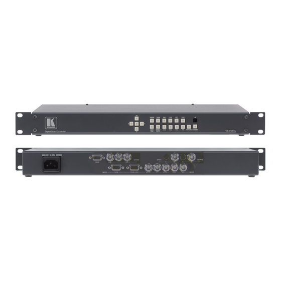
Page 20: Product Images
PRODUCT IMAGES Your product should look like one of the units below. The rack-mount units have built-in power supplies. VP-701XL VP-703XL VP-704XL... -
Page 21: Front Panel Controls
Several other buttons on the front panel provide quick access to certain features of the unit. VP-701XL & VP-703XL front panel VP-704XL front panel Button controls A sub-set of the following buttons will be available on the front of the unit,... -
Page 22: Special Button Combinations And Functions
Jumps to the Zoom pan menu item and allows immediate panning of a zoomed image using multi-directional switch. AUTO Activates Auto Trak for the analog RGB input TRAK ASPECT Changes the aspect ratio of the output. This cycles between 3 RATIO different settings. -
Page 23: Forcing Ntsc Output Resolution
exception of repeating the above combination to un-lock the unit and for storing the current locked buttons setting (thus letting you make sure the unit always starts up with the buttons locked). The IR remote’s LOCK and STORE buttons will always be active, giving another way to turn button/IR remote locking off. -
Page 24: Inputs And Outputs
The units have different video inputs and outputs depending on your model. VP-701XL & VP-703XL rear panel (Not shown is the VP-701XL’s 12v DC input, nor the VP-703XL’s AC mains input.) VP-704XL rear panel (Not shown is the VP-704XL’s AC mains input.) -
Page 25: Video Outputs
The CV and YC outputs always function simultaneously and can be set to either standard NTSC or PAL – see ‘Adjust outputs’ for more information. The VP-701XL and VP-703XL both have dual CV/YC outputs – all four connections are active simultaneously, showing identical images. -
Page 26: Infra-Red Remote Control
INFRA-RED REMOTE CONTROL Your unit is compatible with infra-red remote controls as shown below: Resets back to power-on defaults Stores current Selects input: settings 1/2/3=RGB/CV/YC Enables Keyer Enables Lock & Mix mode Fades in/out Starts AutoSet Locks the IR & panel buttons (Not used.) Selects flicker Sets Shrink/PIP... -
Page 27: Menu Layout And Settings Adjustment
MENU LAYOUT AND SETTINGS ADJUSTMENT From here on, we’ll be looking at the menu structure employed in the series and, more importantly, the individual menu items that allow you to take advantage of the power of the unit. You’ll be using the MENU and buttons and the on-screen display (OSD) to view the options and settings available to you. -
Page 28: Group Names And Descriptions
(Model number) Kramer Electronics The first is the ‘welcome’ display shown above indicating the model of the unit. kramerelectronics.com SW: 65. PT: 12, BT: 13 Moving to the next menu item displays the firmware information screen (the numbers on your unit will be different to those shown). The SW number refers to the version of firmware loaded into the unit, this can be upgraded from our website. - Page 29 selected lock source (RGB1 in this example). The lock mode can be either Off, Genlock or Lock & Mix, with the operation of these shown in the following table: Lock mode Description The output resolution of the Output is defined by the setting for Output Resolution and there will be no background source visible.
-
Page 30: Items Associated With The Adjust Windows Group
Adjust outputs Output type [RGBHV] This menu item allows you to select the type of signal output your unit will provide. Types of output vary depending on the resolution selected and include various types of component signals Y/R-Y/B-Y or YPbPr, the full range of RGB type signals RGBHV, RGBS and RGsB (Sync on green). - Page 31 Adjust windows Zoom level % [ 100] Changing this option, sets the amount of picture magnification you wish to use for the window Source. You are provided with the options to zoom the image from 100% to 1000% (10x zoom). Adjust windows H/V zoom % [100] [100]1.333...
- Page 32 Adjust windows Shrink level% [ 50] [On] Shrink Level determines the percentage of the monitor’s total available screen space that the selected Window image occupies. Adjustment is provided for a reduction down to 10% of the overall output size. In most cases, this feature is used for picture-in-picture (PIP) when a background image is being used (for units with overlay abilities).
- Page 33 Zoom and Shrink functions to be adjusted independently, thus allowing custom aspect ratios to be created, or to convert from one aspect ratio to another. When left as “Simple”, the H/V components of Zoom and Shrink are adjusted equally i.e. H is equal to V.
-
Page 34: Items Associated With The Adjust Keyers Group
picture to break-up at the point of the switch (as the unit synchronizes with a new source). This feature is normally left On. However, if you have a very unstable input, such as a video tape player with a poor (jumping) output signal, you may wish to turn the feature off. - Page 35 NTSC NTSC NTSC NTSC (XGA is 1024x768) You will see that the Swap between foreground and background has no effect on the output resolution as this is always set by the Lock source. Adjust keyers Y Key min/max [ 0] [ 32] The Min/Max parameters are used to select what range of Y (luminance/grey-scale) values are made transparent within the selected window/lock source.
-
Page 36: Items Associated With The Adjust Sources Group
Items Associated with the Adjust sources group The ‘Adjust Sources’ menu group accesses the parameters associated with the processing amplifiers used for each input (RGB, CV, YC, etc.). They allow you to fine-tune an incoming signal to optimize its color, brightness or even sharpness. Not all settings are available for all input types. - Page 37 Source: RGB1 BR size adj. 0] [ 0] This menu item allows manual positioning of the Bottom and Right portion of the image. These settings are often used to correct the position of a PC signal on an input, or to eliminate any undesired noise at the top or bottom of a PAL or NTSC video source.
- Page 38 Source: RGB1 RGB input type [RGBHV] There are several types of signals that are called RGB signals as a generic term. Each has slightly different characteristics that set it apart from similar RGB signals – such as how the synchronization signal is sent. This menu item lets you set the input type to use.
-
Page 39: Cv & Yc Source Menu Items
Film 3:2 Enables 3:2 pull down conversion of the incoming NTSC video. (This option is ignored if the source is not NTSC video). M. Comp Low Enables Pixel Adaptive Motion Compensation. Three levels M. Comp Med. are available with ‘Low’ providing the least compensation M. -
Page 40: Items Associated With The Adjust Resolutions Group
Fortunately, your unit provides a way for you to make the two signals occur at the same time on the selected image. The adjustment range provides both positive and negative levels of delay with 0 being the default. Items associated with the Adjust resolutions group The Adjust Resolutions Menu Group only appears when the Advanced Menus function is turned on within the System Menu Group. - Page 41 800 x 600 60 Hz Interlaced [ Off] This adjustment specifies whether the image is interlaced or progressive scan. It toggles simply On or Off, so there are no flashing brackets. 800 x 600 60 Hz H.freq.crse [37.879] kHz Course Frequency Adjust The H freq.crse (Horizontal Sync Frequency - Course) adjustment provides the option for changing the Horizontal Sync timing Frequency in 100 Hz steps.
- Page 42 The well-known 800 x 600 computer resolution standard simply means that there are 800 pixels/line visible horizontally and there are 600 lines visible vertically. This item provides a way to change the number of active pixels and lines. 800 x 600 60 Hz H/V Start [ 88] x 23 There is a period of time between the end of the Horizontal Sync pulse and the...
-
Page 43: Items Associated With The System Group
+H+V -H+V +H-V -H-V Items Associated with the System group The final Sub Menu is for adjustments of System parameters. The “System” in this case means the unit’s functions that are generally unrelated to individual inputs, outputs or any of the various production features. System SW: 16, PT: 12,... - Page 44 System Push to store This screen provides a quick and easy way to store all current operating parameters. The unit will remember the set up you are currently using at the time of data storage and also when you next apply power. To store the current settings, press and release the control button.
- Page 45 System Resolutions This screen is an informational screen showing the total number of the defined resolutions in the resolution database. Future firmware releases may increase the total number of resolutions defined in the database. System Power cycles Power Cycles refers to how many times the unit has been powered since it left the factory.
-
Page 46: Rs232 Port
RS232 PORT Connection Your unit is fitted with a standard ‘D9’ socket allowing it to be controlled from a computer or other type of terminal or console with a similar interface. Most computers fitted with an RS232 port, known as a ‘COM’ port, will have a ‘D9’ plug on them. -
Page 47: Rs232 / Ip Control Specification
RS232 / IP CONTROL SPECIFICATION PLEASE NOTE: Not all units support RS232 and/or IP (Ethernet) communications – check earlier in the manual to see if this feature is present on your unit. This section outlines how to control a unit via an RS232 or Ethernet link (if fitted to your unit), using ASCII-based commands. -
Page 48: Packet Format
The ACK flag will be returned as 0 if the command is invalid for some reason – for example a bad FUNCTION, WINDOW, OUTPUT or PAYLOAD value. An ACK=0 message will be otherwise identical to the one you sent, so you know exactly which message has the error. - Page 49 returned means message was okay. ACK=0 returned means an error was present in the message. Bit 5 = 0 Reserved for future use. Bit 4 = 0 Reserved for future use. Bit 3 = 0 Reserved for future use. Bit 2 = 1 This bit *must* be set. Bit 1 = 0 Reserved for future use.
-
Page 50: Function List
eg. '000001' is 1 in decimal, '010000' is 65536 in decimal, and 'FFFFF0' is -16 in decimal. ASCII-hex byte that is the (check) sum of all previous bytes (excluding the SOP 'F' character). Eg. The command F0400410082000001 has the checksum of 04+00+41+00+82+00+00+01=C8, so the complete command to send is F0400410082000001C8. - Page 51 Adjust outputs Lock source (connector) 0x10 = RGB1, 0x11 = RGB2, 0x12 = RGB3 0x30 = CV1, 0x31 = CV2, 0x32 = CV3 0x40 = YC1, 0x41 = YC2, 0x42 = YC3 0x50 = SDI1, 0x51 = SDI2 0xD0 = OUT1, 0xD1 = OUT2 0xF0 = TC1, 0xF1 = TC2 Lock method 0..2 = Off, Genlock, Lock &...
- Page 52 0x50 = SDI1, 0x51 = SDI2 0xD0 = OUT1, 0xD1 = OUT2 0xF0 = TC1, 0xF1 = TC2 Window Enable 0..1 = Off, On Zoom level % 100..1000 Zoom level H % 100..1000 (only used in Advanced A/R mode) Zoom level V % 100..1000 (only used in Advanced A/R mode) Aspect ratio in...
- Page 53 Logos Logo enable 0..1 = Off, On Logo number 0..9 Logo selection H/V out shift (H) 0..100 % H/V out shift (V) 0..100 % Max fade level 0..100% Layer priority 0..5 Borders Border enable 0..1 = Off, On Border H size 0..99 Border V size 0..99...
- Page 54 Contrast 3..8 0BC 0..180 Saturation 3..8 0B9 0..180 3..8 0BA -180..180 Sharpness 3..8 080 -7..+7 Luma delay 3..8 0BD -4..3 Adjust transitions (on certain models only) Transition type 0..2 = Cut, fade, wipe Switching fade time 0 (off) to 50 (5.0 seconds) Wipe type 0 = Left ->...
-
Page 55: Examples
Resolutions Read only Number of testcards Read only Number of logos Read only Board temp. (deg.C) Read only Air temp. (deg.C) Read only Regulators temp.(deg.C) Read only PLD temp. (deg.C) Read only Fan speed (rpm) Read only Led brightness 0..100 RS232 Baud rate 0..6 = 9600, 19200, 28800, 33600, 38400, 57600, 115200... -
Page 56: Common Operations
COMMON OPERATIONS This section provides step by step instructions for some common operations. 11.1 Operation of the Keyer Some units come equipped with a very powerful Luminance and Chrominance Keyer. The Keyer can take some time to master and below is a breakdown and series of simple steps to help you master the Keyer’s operation When adjusting the values, please bear in the mind the following: The Y value is the Luminance value, so 0 is black and 255 is very bright (white). - Page 57 Adjust any of the Softness values to improve the key. If your input signal is slightly noisy or if you want to soften the edges within the image, then this may require you to decrease the ‘min’ values and increase the ‘max’ values to broaden the range of colors keyed out.
-
Page 58: Troubleshooting And Technical Support
TROUBLESHOOTING AND TECHNICAL SUPPORT If problems are experienced, please read through the symptom topics below in order to resolve the problem. After doing so, if you still need to, contact Technical Support at http://www.kramerelectronics.com. Please have the following details of the problem handy: Whether the problem happens only at specific times or has only just started occurring (and what other things have changed at the same time). -
Page 59: There Is Excessive Flicker On The Output
Either manually correct the resolution data, or restore the data to full factory conditions by doing a firmware update. The user should avoid altering the resolution parameter data unless absolutely necessary. 12.4 There is excessive flicker on the Output. Try using a different Flicker reduction mode. Turning the contrast down and the brightness up on the output device can have a large effect on flicker. -
Page 60: The Picture On The Video Display Is Green
12.10 The picture on the video display is green. The Output type is probably incorrectly set to YUV mode, whereas you are connecting to an RGB monitor – see Adjust outputs menu. 12.11 The RGB input is selected but the image is rolling or pink. Check the Adjust sources menu and confirm that the input type and sync method is set correctly. -
Page 61: Return Procedure
RETURN PROCEDURE Before returning your unit for repair, there are several checks you can make yourself to make sure the problem is actually caused by a failure. 13.1 Are you sure there's a fault? Many 'faults' are due to incorrect set-up or use so a simple checklist is provided below to help you identify potential problems. -
Page 62: Connector Pinouts
CONNECTOR PINOUTS 14.1 HD15 connector 1. Red / Pr / R-Y 2. Green / Y 3. Blue / Pb / B-Y 4. ID2 (input & output linked) 5. GND 6. GND 7. GND 8. GND 9. No connection 10. GND 11. -
Page 63: Specifications
SPECIFICATIONS See product front and rear diagrams for details of product I/O. Not all units in the series have all the inputs and outputs listed here. 15.1 Video Inputs Input impedance: 75 Ohm Television standards supported: NTSC and PAL Composite video via BNC S-Video (YC) via 4-Pin mini-DIN Connector CV/YC video decoder: 8-bit Digital De-Interlacing (NTSC / PAL up-conversion only): pixel-level motion adaptive... -
Page 64: Locking/Mixing
Connectors: HD-15 and/or 5 x BNC PC Resolutions: any up to 2048x2048 (user adjustable) HDTV Resolutions: any up to 1080p Vertical Refresh Rate: any to 250Hz 15.5 Locking/Mixing CV/YC SC/H phase adjustments: +/- 180 degrees (for units with CV/YC output only) Keyer: chromakey (YUV) or lumakey (Y) Mixer: PC / Video, foreground/background swappable... -
Page 65: Power Requirement
Storage humidity: 10% to 85%, non-condensing 15.10 Power Requirement External power supply: 12V DC @1A maximum. Actual current consumption varies between units. Internal over-voltage & over-current protection. Full PSU specification: 12v DC regulated 1Amp PSU with a 2.5mm locking center- pin positive DC power connector. -
Page 66: Contact Information
CONTACT INFORMATION Should you have and questions or require assistance with this product in areas not covered by this manual, please contact: KRAMER ELECTRONICS, LTD. 3 Am VeOlamo Street. Jerusalem 95463, Israel Tel: (972-2)-654-4000. Fax: (972-2)-653-5369 e -mail: info@kramerel.com... -
Page 67: Warranty Policy
Except as below, this warranty covers all defects in material or workmanship in this product. The following are not covered by the warranty: 1. Any product which is not distributed by Kramer or which is not purchased from an authorized Kramer dealer. If you are uncertain as to whether a dealer is authorized, please contact Kramer at one of the agents listed in the web site www.kramerelectronics.com. - Page 68 EXCLUSION OF DAMAGES Kramer’s liability for any defective products is limited to the repair or replacement of the product at our option. Kramer shall not be liable for: 1.
- Page 69 For the latest information on our products and a list of Kramer distributors, visit our web site: www.kramerelectronics.com, where updates to this user manual may be found. We welcome your questions, comments and feedback. Caution Safety Warning: Disconnect the unit from the power suppler before opening/servicing.
Need help?
Do you have a question about the VP-701XL and is the answer not in the manual?
Questions and answers