Table of Contents
Advertisement
Chapter 1:Introduction of FATEK FBS Series PLC
1.1 Appearance of Main Unit...............................................................................................................H1-1
1.2 Appearance of Expander/Module.................................................................................................H1-2
1.3 Appearance of Communication Expansion Module ....................................................................H1-4
1.4 List of FBS-PLC Models ................................................................................................................H1-5
1.5 Specifications of Main Unit ............................................................................................................H1-7
1.6 Environmental Specifications ........................................................................................................H1-8
1.7 Connection Diagrams of Various Models.....................................................................................H1-9
1.7.1 NC Control Main Unit..............................................................................................................H1-9
1.7.2 Basic/Advanced Main Unit.....................................................................................................H1-10
1.7.3 Digital I/O Expander................................................................................................................H1-12
1.7.4 Digital I/O Expansion Module.................................................................................................H1-13
1.7.5 High-Density Digital I/O Expansion Module ..........................................................................H1-14
1.7.6 Numeric I/O Expansion Module.............................................................................................H1-14
1.7.7 Analog I/O Expansion Module...............................................................................................H1-14
1.7.8 Temperature Input Module.....................................................................................................H1-15
1.7.9 Expansion Power....................................................................................................................H1-15
1.7.10 Communication Module (CM)..............................................................................................H1-16
1.7.11 Communication Board (CB).................................................................................................H1-17
1.8 Drawings with External Dimensions .............................................................................................H1-18
2.1 Single-Unit System of FBS-PLC...................................................................................................H2-1
2.2 Formation of Multiple Units............................................................................................................H2-2
2.2.1 Connection of multiple FBS-PLC...........................................................................................H2-2
2.2.2 Connection of FBS-PLC with host computer or intelligent peripherals................................H2-3
3.1 I/O Expansion.................................................................................................................................H3-1
【Hardware】
Contents
Advertisement
Table of Contents

Related Manuals for FATEK FBS Series


Summary of Contents for FATEK FBS Series
-
Page 1: Table Of Contents
【Hardware】 Contents Chapter 1:Introduction of FATEK FBS Series PLC 1.1 Appearance of Main Unit.......................H1-1 1.2 Appearance of Expander/Module....................H1-2 1.3 Appearance of Communication Expansion Module ..............H1-4 1.4 List of FBS-PLC Models ........................H1-5 1.5 Specifications of Main Unit ......................H1-7 1.6 Environmental Specifications ......................H1-8 1.7 Connection Diagrams of Various Models..................H1-9... - Page 2 3.1.1 Digital I/O Expansion and I/O Numbering ................H3-1 3.1.2 Numeric I/O Expansion and I/O Channel Mapping ..............H3-3 3.2 Expansion of Communication Port ....................H3-4 Chapter 4:Installation Guide 4.1 Installation Environment.........................H4-1 4.2 PLC Installation Precautions ......................H4-1 4.2.1 Placement of PLC........................H4-1 4.2.2 Ventilation Space........................H4-2 4.3 Fixation by DIN RAIL ........................H4-3 4.4 Fixation by Screws.........................H4-4 4.5 Precautions on Construction and Wiring ..................H4-6...
- Page 3 7.3.3 Structure and Wiring of Single-End TRIAC Output Circuit...........H7-5 7.4 Speed up the Single-End Transistor Output Circuit (only applicable to high and intermediate-speed) ..............................H7-6 7.5 Output Device Protection and Noise Suppression...............H7-6 7.5.1 Protection of Relay Contact and Noise Suppression ............H7-6 7.5.2 Protection of Transistor and Noise Suppression..............H7-8 Chapter 8:Test Run, Monitoring and Maintenance 8.1 Inspection after Wiring and before First Time Power on..............H8-1...
- Page 4 【Instruction】 Contents Chapter 1: PLC Ladder Diagram and the Coding Rules of Mnemonic 1.1 The Operation Principle of Ladder Diagram ............1-1 ....................1-1 1.1.1 Combination Logic ....................1-2 1.1.2 Sequential Logic 1.2 Differences Between the Conventional and PLC Ladder Diagram ......1-3 1.3 Ladder Diagram Structure and Terminology ............
- Page 5 Chapter 5: Description of Function Instructions 5.1 The Format of Function Instructions ............... 5-1 ......................5-1 5.1.1 Input Control ............5-2 5.1.2 Instruction Number and Derivative Instructions ......................5-3 5.1.3 Operand ..................5-6 5.1.4 Functions Output (FO) 5.2 Use Index Register(XR) for Indirect Addressing ............. 5-6 5.3 Numbering System ....................
- Page 6 Division (FUN14) ........... 6-30 Increment (FUN15) ........... 6-32 Decrement (FUN16) ........... 6-33 Compare (FUN17) ........... 6-34 Logical and (FUN18) ........... 6-35 Logical or (FUN19) ........... 6-36 Binary to bcd conversion (FUN20) ........... 6-37 Bcd to binary conversion (FUN21) ........... 6-38 Chapter 7:Advanced Function Instructions Flow control instructions1 (FUN22) ............
- Page 7 8.5 Application Examples ..................... 8-15 8.6 Syntax Check Error Codes for Step Instruction ............8-22 【 Appendix 】 DAP Simple Human Machine Interface 1.1 Profile ........................-2 1.2 Important points before operation ................-2 -DAP ................-3 1.3 The Main Functions of FB 1.4 Setter Functions of General Information ..............
-
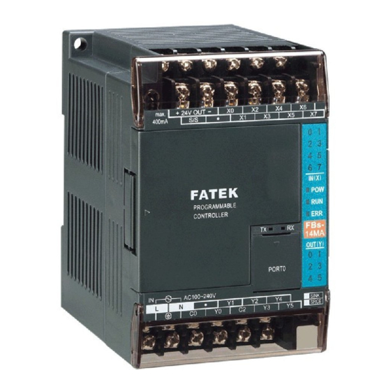
Page 8: Appearance Of Main Unit
【 Hardware】 Chapter 1 Introduction of FATEK FB Series PLC The FATEK FB Series PLC is a new generation of micro PLC equipped with excellent functions comparable to medium or large PLC, with up to five communication ports. The maximum I/O numbers are 256 points for Digital Input (DI) and Digital Output (DO), 64 words for Numeric Input (NI) and Numeric Output (NO). - Page 9 ○ Indicators for transmit (TX) and receive (RX) status of built-in communication port (Port0). ○ Indicator for Digital Input (Xn). ○ Indicator for Digital Output (Yn). ○ Indicator for system status (POW, RUN, ERR). ○ I/O output expansion header cover [units of 20 points or beyond only], with esthetic purpose and capable of securing expansion cable.
- Page 10 Front view of output expansion Output expansion slot 擴充輸出插槽蓋板 指示燈 slot with cover plate removed 移除之正視圖 Output status 輸出狀態 I 2 3 indicator 指示燈 IN X FATEK OUT Y SINK SRCE 擴充輸出插槽 Output expansion slot 擴充輸入 Expansion cable DIN RAIL卡鉤 扁平排線接頭 I/O 端子台 connector...
-
Page 11: Appearance Of Communication Expansion Module
螺絲固定孔 4.5×2 ψ4.5 × 2 擴充輸出插槽蓋板 Front view of output expansion I5 I6 header with cover plate 移除之正視圖 輸入狀態 Input status IN X FATEK 指示燈 indicator Expansion cable 擴充輸入 connector 扁平排線接頭 擴充輸出插槽 Output expansion I/O 牛角插座 I/O Header socket DIN RAIL卡鉤... -
Page 12: List Of Fbs-Plc Models
List of FBS PLC Models Item Name Model Number Specifications 2 points 7920KHz 5VDC differential input, 10 points 24VDC digital input (20KHz), 2 points 7920KHz -20MN□◇Δ–◎ 5VDC differential output, 6 points (R/T/S) digital output (Model “T” 6 points 20KHz output), 1 RS232 or USB port (expandable up to 5), built-in RTC, detachable terminal block 4 points 920KHz 5VDC digital differential input, 16 Points 24VDC digital input (20KHz for 12 Points), NC Control... - Page 13 Hand held programmer for FBs-PLC FP-07C Programming Device WinProladder WinProladder Programming software for Windows FATEK DDE communication server FATEK Comm. Server Extension cable adapter -XTNR Others Include 22AWG I/O cable for 30Pin Header connector, 200cm long ( for FBs-24EX, -24EYT, and...
-
Page 14: Specifications Of Main Unit
Specifications of Main Unit “*” Default Settings Item Specification Note Execution Speed 0.33uS/per Sequence Command Space of Control Program 20K Words Program Memory FLASH ROM or SRAM+Lithium battery for Back-up Sequence Command Application Command 300 (113 types) Include Derived Commands Flow Chart (SFC) Command Corresponding to External Digital Input Output Contact(DI) -
Page 15: Environmental Specifications
1500Vp-p, width 1us Withstand Voltage 1500VAC, 1 minute L, N to any terminal Warning The listed environmental specifications are for FB -PLC under normal operation. Any operation in environment not conform to above conditions should be consulted with FATEK. H1 -8... -
Page 16: Connection Diagrams Of Various Models
1.7 Connection Diagrams of Various Models 1.7.1 NC Control Main Unit [7.62mm Detachable Terminal Block] 20 point digital I/O main unit (12 points IN, 8 points OUT) 24V OUT max. 400mA -20MN Power AC100~240V SINK SRCE 24V OUT max. 400mA Power -20MN-D 24VDC... -
Page 17: Basic/Advanced Main Unit
1.7.2 Basic/Advanced Main Unit [7.62mm Terminal Block, fixed in model MA, detachable in models MC/MN] 10 point digital I/O main unit (6 points IN, 4 points OUT) 14 point digital I/O main unit (8 points IN, 6 points OUT) 24V OUT 24V OUT max. - Page 18 32 point digital I/O main unit (20 points IN, 12 points OUT) 24V OUT max. 400mA -32MA / FB -32MC Power AC100~240V SINK SRCE 24V OUT max. 400mA Power -32MA-D / FB -32MC-D 24VDC SINK SRCE 40 point digital I/O main unit (24 points IN, 16 points OUT) 24V OUT max.
- Page 19 1.7.3 Digital I/O Expansion Unit [7.62mm fixed terminal block] 24 point I/O expansion unit (14 points IN, 10 points OUT) 24V OUT max. 400mA -24EAP Power AC100~240V SINK SRCE 24V OUT max. 400mA Power -24EAP-D 24VDC SINK SRCE 40 point I/O expansion unit (24 points IN, 16 points OUT) max.
-
Page 20: Digital I/O Expansion Module
1.7.4 Digital I/O Expansion Module [7.62mm fixed terminal block] 8 point digital I/O module (4 points IN, 4 points OUT) 8 point digital input module (8 points IN ) -8EA -8EX SINK SRCE 8 point digital output module (8 points OUT) 16 point digital I/O module (8 points IN, 8 points OUT) -8EY -16EA... -
Page 21: High-Density Digital I/O Expansion Module
1.7.5 High-Density Digital I/O Expansion Module [30Pin/2.54mm Header connector] 24 point high-density input module 24 point high-density transistor output module (24 points IN) (24 points OUT, SINK Type) -24EX -24EYT S/S1 S/S2 S/S3 29 30 1.7.6 Numeric I/O Expansion Module [2.54mm Header connector] 7 segment LED display module Thumbwheel switch multiplex input module... -
Page 22: Temperature Input Module
4 channel D/A output module 4 channel A/D input, 2 channel D/A output module -4DA -4A2D 1.7.8 Temperature Input Module [7.62mm fixed terminal block] 2/6 channel thermocouple input module 16 channel thermocouple input module -TC2/TC6 -TC16 T12+ T13+ T14+ T15+ T10+ T11+ T14-... -
Page 23: Communication Module (Cm)
1.7.10 Communication Module (CM) [DB-9F connector/3Pin or 4Pin Plug able terminal block] 2 RS232 ports 2 RS485 ports FBs-CM55 FBs-CM22 1 RS232 + 1 RS485 ports 1 RS232 + 1 RS485 + Ethernet FBs-CM25 FBs-CM25E 2 RS485 ports + Ethernet RS232 RS485 Converter RS232 to RS485... -
Page 24: Communication Board (Cb)
1.7.11 Communication Board (CB) [DB9F/3Pin plug able terminal block](Below are outlooks of CB and the corresponding cover plates) 1 RS232 port 2 RS232 ports PROGRAMMABLE PROGRAMMABLE CONTROLLER CONTROLLER PORT2 PORT1 PORT2 PORT1 -CB2 -CB22 1 RS485 port 2 RS485 ports PROGRAMMABLE PROGRAMMABLE CONTROLLER... -
Page 25: Drawings With External Dimensions
1.8 Drawings with External Dimensions (1) Outlook I: Main Unit:FB -10M△, FB -14M△ Expansion Module:FB -16E△, FB -20EX * (Main Unit and Expansion Module have the same type of base, with different top cover, as shown in the figure) PROGRAMMABLE CONTROLLER 2 - 4.5 units:mm... - Page 26 ○ 1 and 2 have the same type of base, with different top cover. Top cover of Module 1 is shown in *(Modules the following figure) FATEK 2 - 4.5 units:mm ( 4 ) Outlook IV: Communication Module:FB -CM22, FB...
- Page 27 Outlook V: Programming Panel:FP-07C units : mm (6) Outlook VI : Data Access Panel : FB-DAP 17.6 9.98 H1 -2 0...
-
Page 28: Chapter 2 System Architecture
Chapter 2 System Architecture Single-Unit System of FB -PLC The Single-Unit system means a system built only by a single FBs-PLC and its expansion unit/modules and communication boards/modules. Such system have a limited capability (refer), beyond that capability can incorporate CPU communication via LINK function for expansions (please refer to the next paragraph). -
Page 29: Connection Of Multiple Fbs-Plc
Regarding communication resources, the FBs-PLC hardware can accommodate up to 5 communication ports (with a maximum speed of 921.6Kbps). In addition to providing the standard FATEK communication protocol, it also supports the Modbus master/slave protocol or any user-defined protocol. This functionality easily renders the connections with intelligent peripherals such as electronic scale, bar code reader, and various meters and gauges. -
Page 30: Connection Of Fbs-Plc With Host Computer Or Intelligent Peripherals
Connection can be established as long as the upper-level computer or intelligent peripherals use either one of the two protocols. In the application, in which driver for FATEK or Modbus is not available, FATEK also provide standard DDE communication server, which enables FBs-PLC to connect with any computer system supporting DDE. -
Page 31: Chapter 3:Expansion Of Fbs-Plc
Chapter 3 Expansion of FB -PLC If the I/O point of the. Main unit of the applied FB -PLC is not enough for a specific application, then can expand it with the additional expansion units/modules. Besides I/O point there also have the requirements to expand the communication port in some occasions. - Page 32 main unit. Users can easily find each terminal with its I/O number and LED status indication, as shown in the figure below using X10 and Y6 as an example: max. 24V OUT 400mA I0 I I IN X PROGRAMMABLE CONTROLLER OUT Y PORT0 AC100~240V...
-
Page 33: Numeric I/O Expansion And I/O Channel Mapping
3.1.2 Numeric I/O Expansion and I/O Channel Mapping The numeric I/O in FBs-PLC treat 16 single-bit data as one 16-bit numeric data (Word) ranging from the 0~65535. Since all numeric data of FBs-PLC are stored in the register inside PLC (16-bit width), therefore numeric I/O is also called register I/O. -
Page 34: Expansion Of Communication Port
(In the cumulative calculation of NI channels, care only for NI channels and disregard DI/O and NI. Similarly, in the case of NO channels, disregard DI/O and NI channels.) The following figure helps users find out the relation between NI/O channels and PLC’s IR and OR. FATEK 24V IN 24V IN... - Page 35 Model Number Specifications 1 RS232 (port2) communication board FBs-CB2 2 RS232 (port1 & port2) communication boards FBs-CB22 1 RS485 (port2) communication board FBs-CB5 2 RS485 (port1 & port2) communication boards FBs-CB55 FBs-CB25 1 RS232 (port1) + 1 RS485 (port2) communication board FBs-CBE 1 Ethernet communication board 2 RS232 (port3 &...
-
Page 36: Installation Environment
PORT0 AC100~240V SINK SINK SINK SRCE SRCE SRCE Suggested arrangement max. 24V OUT of multiple unit expansion 400mA 多台擴充之 建議排列方式 IN X IN X FATEK PROGRAMMABLE PROGRAMMABLE CONTROLLER CONTROLLER OUT Y OUT Y AC100~240V SINK SINK SRCE SRCE H4 -1... -
Page 37: Ventilation Space
4.2.2 Ventilation Space The heat in FB -PLC is ventilated via air circulation. There should reserve more than 20mm space, both below and above PLC, and with vertical installation, for ventilation. as shown in the figure below: Heat ventilation 熱氣逸散方向 吸頂... -
Page 38: Fixation By Din Rail
4.3 Fixation by DIN RAIL In an environment with slight vibration (less than 0.5G), this is the most convenient way of fixation and is easy for maintenance. Please use DIN EN50022 DIN RAIL, as shown in the figure below. 35mm 1.0mm (1.38 in.) (0.039 in.) -
Page 39: Fixation By Screws
4.4 Fixation by Screws In environments with larger vibration (more than 0.5G), the unit must be secured by M3 or M4 screws. Positions and sizes of screw holes in various models of FB -PLC are illustrated in the following: 60mm 尺寸... - Page 40 1750mm 尺寸 Size D: (6.890in) (0.157in) 90mm (3.543in) 2 - 4.5 (0.177 in) 21mm (0.827in) 40mm 尺寸 20mm Size E: (1.575in) (0.787in) 90mm (3.543in) 3.8mm (0.150in) 2 - 4.5 (0.177 in) 21mm (0.827in) 25mm 尺寸 Size F: 3.8mm (0.984in) (0.150in) 90mm (3.543in) 2 - 4.5...
-
Page 41: Precautions On Construction And Wiring
4.5 Precautions on Construction and Wiring 1. During the wiring of FB –PLC, please follow local national standards or regulations for installation. 2. Please chose the wires with proper wire gauge for I/O wiring according to the current loads. 3. Shorter wires are preferred. It is advised that the length of I/O wiring does not exceed 100m (10m for high-speed input). - Page 42 Chapter 5 Power Supply Wiring, Power Consumption Calculation, and Power Sequence Requirements -PLC internally has three kinds of circuit: a 5VDC logic circuit, a 24VDC output circuit, and a 24VDC input circuit. They are all powered by the built-in power supply of main/expansion units. Expansion modules other than main/expansion units do not contain any power supply and are powered by the power supply inside the main/expansion units or expansion power supply (FB -EPOW).
- Page 43 Note The schematic diagram of AC power supply wiring in main/expansion units is shown below. Also be cautious about the following: Please follow the wiring schemes regulated by local national standards to use single-pole switch(break hot wire 〝L〞 ), or double-pole switch(break both〝L〞and〝N〞 ), to turn on or off the AC input power. In wiring, hot wire〝L〞must be connected to the L terminal on unit, while the ground line〝N〞connected to the terminal.
- Page 44 Model Sp e c . POW-10-D POW-16-D -EPOW-D Item Rated Voltage 24VAC -15% / 20% Max. Power Consumption Inrush Current 20A@24VDC Allowable Power Interrupt 20ms(min.) 3A,250VAC Fuse Spec. Isolation Type Transformer/Photo Coupler Isolation, 500VDC/minute 5V,±5%,1A(max) 5V,±5%,0.4A(max) 5VDC(logic circuit) N/A* 24V±10%,200mA(max)* 24V,±10%,400mA(max) 24V,±10%,250mA(max) 24VDC(output circuit) Directly from input power, but limited by specifications of circuit and fuses, with...
-
Page 45: Residual Capacity Of Main Unit/Expansion Unit
5.3 Residual Capacity of Main/Expansion Unit & Current Consumption of Expansion Module Besides its own circuits usage, the residual capacities of three sets of built-in power supply of main/expansion unit are big enough for other expansion modules usage. In addition, the expansion power (FB -EPOW) module can also provides the power for expansion modules usage. -
Page 46: Maximum Current Consumption Of Expansion Module
5.3.2 Maximum Current Consumption of Expansion Module Without its own power supply, expansion modules must be supported by the main/expansion unit, expansion power, or external power supply (24VDC input circuit alone). The following table lists the maximum consumption current of each expansion module. - Page 47 5.4 Requirement of Power Sequence in Main Unit & Expansion Unit/Module When the power is on, the FB -PLC main unit first detects the type and number of expansion unit/module attached to its expansion interface and get the actual I/O configuration. Therefore, while the main unit performs detection, the power in expansion unit/module should be already UP, otherwise, the detected I/O configuration will not correct.
-
Page 48: Specifications Of Digital Input (Di) Circuits
Chapter 6 Digital Input (DI) Circuit The FB -PLC provides the ultra high speed differential double end 5VDC inputs (i.e., single input with two terminals without common) and the single-end 24VDC inputs which use the common terminal to save terminals. The response speeds of single-end common input circuits are available in high, medium and low. -
Page 49: Structure And Wiring Of 5Vdc Ultra High Speed Differential Input Circuit
6.2 Structure and Wiring of 5VDC Ultra High Speed Differential Input Circuit Only the MN main unit of FBs provides the 5VDC ultra high speed differential input circuit, which is mainly used for the input of hardware high speed counter (HHSC) with a maximum working frequency up to 920 KHz. In practice, to ensure the high speed and high noise immunity, please use Line-Driver for differential line driving. -
Page 50: 24Vdc Single-End Input Circuit And Wiring For Sink/Srce Input
6.3 24VDC Single-End Input Circuit and Wiring for SINK/SRCE input The 24VDC single-end digital input circuits of FB -PLC are available for high, medium and low speed. They all have the similar circuit structures but with different response speeds. To save input terminals, the circuit of single-end input is implemented by connecting one end of all input points (photo coupler) inside the PLC to the same internal common point labeled as S/S. -
Page 51: Specifications Of Digital Output Circuits
Chapter 7 Digital Output (DO) Circuit The digital outputs of FB -PLC are available in the following two structures: the 5VDC ultra high speed Line-driver type differential output (i.e., one output occupying two terminals), and the single-end output circuit for saving terminals. There are three kinds of output device for the single-end output, which are relays, TRIAC and transistors. - Page 52 Differential Item Single-End Transistor Output Output Single-End Relay Single-End TRIAC Output Ultra High High Medium Output Specification Speed Speed Speed Speed Maximum switching 920KHz(1-phase) 100KHz 20KHz 200HZ For ON/OFF, not for frequent exchange (working) Frequency 460KHz(2-phase) <250VAC,30VDC Working Voltage 5VDC±10% 5~30VDC 100~240VAC 2A/single,...
-
Page 53: 5Vdc Ultra High Speed Line-Driver Differential Output Circuit And Its Wiring
7.2 5VDC Ultra High Speed Line-Driver Differential Output Circuit and its Wiring The 5VDC ultra high speed Line-Driver differential output circuit of FB -PLC is only available for the main unit of the MN model. Its output can connect to general photo coupler circuit or Line-Receiver input circuit, with the connection shown in the figure below. -
Page 54: Structure And Wiring Of Single-End Transistor Sink & Srce Output Circuit
- P L C AC/DC AC/DC AC/DC AC/DC 電源 電源 power power FUSE FUSE 動 作 次 數 萬 次 接點電流(A) Contact Current (A) 7.3.2 Structure and Wiring of Single-End Transistor SINK and SRCE Output Circuit Transistor Single-End SINK Output -PLC FUSE FUSE... -
Page 55: Structure And Wiring Of Single-End Triac Output Circuit
Transistor Single-End SRCE Output -PLC FUSE FUSE power 電源 2PTs Common Output Block 共點輸出區塊 4PTs Common Output Block 共點輸出區塊 The figure above uses output block s of 2PTs common and 4PTs common as an example to explain the differences in structural and wiring for SINK and SRCE output circuits, respectively.(8PTs common has the same block structure and wiring, except with different point number) The single-end SINK output and SRCE transistor output in FB -PLC are... -
Page 56: Speed Up The Single-End Transistor Output Circuit (Only Applicable To High And Intermediate-Speed)
7.4 Speed up the Single-End Transistor Output Circuit (only applicable to high- and medium-speed) Either with the SINK or SRCE structure in single-end output transistor circuit, when the transistor switches from ON to OFF, the junction capacitor between transistor CE electrodes should be charged to near the load voltage VDD before it can stop the current running through the photocoupler inside the load, which increase the OFF time and decrease the response speed. - Page 57 A. Suppression of Surge Current 以 Connect a small resistor R in series to lower the surge current, but note that too large R will affect the driving capability or cause too much voltage drop. PLC output 輸出 relay 繼電器 Load Load 湧浪電流使接點熔化黏住...
-
Page 58: Protection Of Transistor And Noise Suppression
7.5.2 Protection of Transistor Output and Noise Suppression The transistor output in FB -PLC already includes Zener diode for counter-electromotive force, which is sufficient for low power inductive load and medium frequency of ON/OFF application. In conditions of high power or frequent ON/OFF, please construct another suppression circuit to lower noise interference and prevent voltage from exceeding the limit or overheating that may damage the transistor output circuit. -
Page 59: Chapter 8 Test Run, Monitoring And Maintenance
Chapter 8 Test Run, Monitoring and Maintenance Warning During maintenance, be sure to turn off the input power of PLC in case the actions to touch any terminal on PLC, or insert and extract accessories (e.g., expansion ribbon cables) is required. Otherwise, electric shock, short circuit, damaged PLC or PLC malfunction will be caused if the power is on. - Page 60 8.3 LED Indicators on PLC Main Unit and Troubleshooting 輸入狀態指示 "Xn" Input Status Indicator “Xn” 24V OUT max. 400mA 電源指示 "POW" Power Indicator “POW” 0 I 2 3 5 6 7 Receive Indicator “RX” 接收指示 "RX" IN X 運轉指示 "RUN" Operation Indicator “RUN”...
- Page 61 Error Description Code Application program contains the functions not supported by this Mismatch of PLC ID VS. program ID Check sum error in LADDER program System STACK abnormal Watch-Dog occurs Exceed main unit I/O Syntax check error occurs Expansion I/O modules over limit Expansion I/O points over limit System FLASH ROM CRC error Reserved...
-
Page 62: Maintenance
Not overloaded, but the inductive load without proper snubber circuit causes high voltage sparks between relay contact at 〝OFF〞 and generate carbon deposition, which separates contacts and causes permanent OFF or intermittent ON/OFF, or punches through transistor or TRIAC with high voltage, resulting in permanent ON or OFF. 8.4 Maintenance -PLC itself has no user serviceable parts and all maintenance has to be conducted by professional personnel. -
Page 63: Chapter 1 Plc Ladder Diagram And The Coding Rules Of Mnemonic
【Instruction】 Chapter 1 PLC Ladder Diagram and the Coding Rules of Mnemonic In this chapter, we would like to introduce you the basic principles of ladder diagram, in addition, the coding rules of mnemonic will be introduced as well, it's essential for the user who use FP-07C as a programming tool. If you are familiar with PLC Ladder Diagram and mnemonic coding rules, you may skip this chapter. -
Page 64: Sequential Logic
Conventional Ladder Diagram PLC Ladder Diagram circuit 1 circuit 1 circuit 2 circuit 2 circuit 3 circuit 3 The above example illustrated the combination logic using the actual wiring diagram, conventional Ladder Diagram, and PLC Ladder Diagram. Circuit 1 uses a NO (Normally Open) switch that is also called "A" switch or contact. Under normal condition (switch is not pressed), the switch contact is at OFF state and the light is off. -
Page 65: Differences Between The Conventional And Plc Ladder Diagram
Conventional Ladder Diagram PLC Ladder Diagram When we first connect this circuit to the power source, X6 switch is ON but X5 switch is OFF, therefore the relay Y3 is OFF. The relay output contacts 1and 2 are OFF because they belong to A contact (ON when relay is ON). Motor does not run. If we press down the switch X5, the relay turns ON as well as contacts 1and 2 are ON and the Motor starts. - Page 66 Input processing (Reading the status of all external input terminals) First step PLC sequentially executes M100 the stored program and gets new output results (has not sent to external terminals yet) Y126 X100 M505 Last step Output processing (Output the resulting signals to external output terminals) Besides the time scan difference mentioned above, the other difference between the conventional and PLC Ladder Diagram is “Reverse flow”...
-
Page 67: Ladder Diagram Structure And Terminology
1.3 Ladder Diagram Structure and Terminology Sample Ladder Diagram Element Node Parallel block Serial block Element Node Parallel block Serial block Origin line Origin line Branch Branch Network 1 Network 1 Network 2 Network 2 Network 3 Network 3 (Remark:The maximum size of FBs-PLC network is 16 rows×22 columns) As shown above, the Ladder Diagram can be divided into many small cells. - Page 68 We must energize the coil of relay first (using OUT instruction) in order to turn on the relay. After the coil is energized, its contact status will be ON too. As shown in the example above, if Y0 turns ON, then the relay contact A is ON and contact B is OFF, TU contact only turns ON for one scan duration and TD contact is OFF.
- Page 69 Node: The connection point between two or more elements(please refer to section 5.3) Block: a circuit consists of two or more elements. There are two basic types of blocks: • Serial block:Two or more elements are connected in series to form a single row circuit. Example: •...
-
Page 70: The Coding Rules Of Mnemonic
Network: Network is a circuit representing a specified function. It consists of the elements, branches, and blocks. Network is the basic unit in the Ladder Diagram which is capable of executing the completed functions, and the program of Ladder Diagram is formed by connecting networks together. The beginning of the network is the origin line. - Page 71 Remark 2: Also using the AND instruction directly if an OUT TR instruction has been used at a branch line to store the node statuses. Example: OUT TR OUT TR0 LD TR0 LD TR Using AND instruction for serial connection of a single element. Example: Using OR instruction for parallel connection of a single element.
- Page 72 ANDLD instruction is used to connect parallel blocks in series. Example: ORLD Must use ANDLD instruction ANDLD The ANDLD instruction must be used if the element or serial block is in front of the parallel block. If the parallel block is in front of the element or serial block, AND instruction can be used to connect all parts together.
-
Page 73: The De-Composition Of A Network
1.5 The De-Composition of a Network (Users of WinProladder can skip this section) The key process of de-composition of a network is to separate the circuits that appear between two vertical lines into independent elements and serial blocks, then coding those elements and serial blocks according to the mnemonic coding rules and then connect them (with ANDLD or ORLD instruction) from left to right and top to bottom to form a parallel or a serial-parallel blocks, and finally to form a complete network. -
Page 74: Using Temporary Relays
1.6 Using Temporary Relays (Users of WinProladder can skip this section) The network de-composition method for mnemonic coding demonstrated in section 1.5 does not apply to the branched circuit or branched block. In order to input the program using the method shown in section 1.5, It must first to store the statuses of branched nodes in temporary relays. -
Page 75: Program Simplification Techniques
Example: OUT TR0 OUT TR LD TR ←─ Begins from row 2 LD TR0 LD TR ←─ Begins from row 3 Example: OUT TR1 OUT TR block 2 block 1 ORLD OUT TR LD TR1 Uses AND Instruction OUT TR0 ←─... - Page 76 When a single element or a serial block is connected in parallel with a parallel block, ANDLD instruction can be omitted if put the parallel block in front. ORLD ANDLD If the branch node of a branch circuit is directly connected to the output coil, this coil could be located on top of the branch line (first row) to reduce the code.
- Page 77 Conversion of the bridge circuit This network structure is not allowed in PLC program 1 - 15...
- Page 78 MEMO...
-
Page 79: Chapter 2 Fbs-Plc Memory Allocation
Chapter 2 FBs-PLC Memory Allocation 2.1 FB -PLC Memory Allocation Remark: SRAM -PACK 1. When the Read Only Register (ROR) has been configured by the user, the X(256) X255 X255 contents of R5000~R8071 (depends Y(256) Y255 Y255 on the quantity of configuration) will T(256) T255 T255... -
Page 80: Digital And Register Allocations
2.2 Digital and Register Allocations 〝 *〞 is default, user configurable Typee Symbol Item Range Remarks X0~X255 (256) Digital Input (DI) Mapping to external digital I/O Y0~Y255 (256) Digital Output (DO) TR0~TR39 (40) Temporary Relay For branched points M0~M799 (800)* Non-Retentive M0~M1399 configurable as M1400~M1911 (512) -
Page 81: Special Relay Details
Remark: During power up or changing operation mode from STOP→RUN, all contents in non-retentive relays or registers will be cleared to 0; the retentive relays or registers will remain the same state as before. 2.3 Special Relay Details Relay No. Function Description 1. - Page 82 Relay No. Function Description 3. Pulse Signals ◤M1920 0.01S Clock pulse T(M1920)=0.01S "1" ◤M1921 0.1S Clock pulse T(M1921)=0.1S "0" ◤M1922 1S Clock pulse T(M1922)=1S T is the pulse period ◤M1923 60S Clock pulse T(M1923)=60S ◤M1924 "RUN" Initial pulse (first scan) "STOP"...
- Page 83 Relay No. Function Description 6. HSC0/HSC1 Controls (MC/MN) M1940 HSC0 software Mask 1: Mask HSC0 software Clear 1: Clear M1941 M1942 HSC0 software Direction 0: Count-up, 1: Count-down Reserved M1943 Reserved M1944 Reserved M1945 HSC1 software Mask 1: Mask M1946 M1947 HSC1software Clear 1: Clear...
- Page 84 Relay No. Function Description Dialing success flag 1: Indicating that dialing is successful (when Port 1 is connected M1965 with Modem). M1966 Dialing fail flag 1: Indicating that dialing has failed (when Port 1 is connected with Modem). M1967 Port 2 High Speed Link working 0: Continuous cycle.
- Page 85 Relay No. Function Description 10. PSO0~PSO3 Controls M1991 Selection of stopping the pulse output 0:Immediately stop while stopping pulse output (FUN140) 1:Slow down stop while stopping pulse output M1992 PSO0 Busy indicator 0:PSO0 Busy 1:PSO0 Ready M1993 PSO1 Busy indicator 0:PSO1 Busy 1:PSO1 Ready M1994...
-
Page 86: Special Registers Details
2.4 Special Registers Details Register No. Function Description Input Registers For Analog or Numeric inputs R3840 CH0 : R3840 │ │ │ R3903 CH63 : R3903 Output Registers For Analog or Numeric outputs R3904 CH0 : R3904 │ │ │ R3967 CH63 : R3967 Raw Temperature Registers... - Page 87 Register No. Function Description R4010 Each bit represents 1 sensor, Installed temperature sensor flag │ if bit value = 1 means installed. R4011 R4012 Each bit represents 1 temperature point, if bit value = PID Temperature control flag │ 1 means enable control. R4013 R4014 Reserved...
- Page 88 =Others : initialize the addressed data registers been written into ROM Pack while power up R4047 Communication protocol setting for Port1~ Set the FATEK or Modbus RTU communication Port4 protocol Transmission Delay & Receive Low Byte:Port 4 Receive Time-out interval time (Unit...
- Page 89 Register No. Function Description R4059 Error code while Port 2 in High Speed CPU Used by FUN151 Mode 3 of Port 2 LINK mode High byte Low Byte R4059 Err code Err count Error code: 0AH, No response 01H, Framing Error 02H, Over-Run Error 04H, Parity Error 08H, CRC Error...
- Page 90 Register No. Function Description R4072 Low Word of PSO 0 R4073 High Word of PSO 0 R4074 Low Word of PSO 1 R4075 High Word of PSO 1 R4076 Pulse count remaining for output Low Word of PSO 2 R4077 High Word of PSO 2 R4078 Low Word of PSO 3...
- Page 91 Register No. Function Description R4096 HSC0 current value Low Word R4097 HSC0 current value High Word R4098 HSC0 preset value Low Word R4099 HSC0 preset value High Word R4100 HSC1 current value Low Word R4101 HSC1 current value High Word R4102 HSC1 preset value Low Word R4103...
- Page 92 Register No. Function Description R4139 CPU Status Bit0 =0, PLC STOP =1, PLC RUN Bit1 , Reserved Bit2 =1, Ladder program checksum error Bit3 =0, Without ROM Pack =1, With ROM Pack Bit4 =1, Watch-Dog error Bit5 =1, MA model main unit Bit6 =1, With ID protection Bit7 =1, Emergency stop Bit8 =1, Immediate I/O over range...
- Page 93 =55H, Remote-Diagnosis/Remote-CPU-Link without checking of station number for by way of Port 1 through Modem connection, it supports user FATEK's external communication protocol program controlled dial up function =AAH, Remote diagnosis by way of Port 1 through Modem connection, it supports Passive receiving &...
- Page 94 Register No. Function Description R4155 Port 1 & Port 2 without station number Low Byte of R4155: checking for FATEK's external =1, Port 1 without station number communication protocol checking for FATEK's external communication protocol (communicating with MMI/SCADA) =Others,Port 1 checks station number, it allows...
- Page 95 Register No. Function Description Low Byte of R4163 : R4163 Modem dialing control setting =1, Ignore the dialing tone and the busy tone when dialing. =2, Wait the dialing tone but ignore the busy tone when dialing. =3, Ignore the dialing tone but detect the busy tone when dialing.
- Page 96 Register No. Function Description D4000 Port 1 User-defined Baud Rate Divisor Port 1 user-defined Baud Rate (1125~1152000 bps) (R4146 must be 56XFH) D4000 = (18432000/Baud Rate) - 1 D4001 Port 2 User-defined Baud Rate Divisor Port 2 user-defined Baud Rate (1125~1152000 bps) (R4158 must be 56XFH) D4001 = (18432000/Baud Rate) - 1 D4002...
-
Page 97: Chapter 3 Fbs-Plc Instruction Lists
Chapter 3 FBs-PLC Instruction Lists 3.1 Sequential Instructions Execution Instruction Operand Symbol Function Descriptions Instruction type Time Starting a network with a normally open (A) contact 0.33uS Starting a network with a normally closed ORG NOT X,Y,M, (B) contact Starting a network with a differential up S,T,C Network ORG TU... - Page 98 PLC’s. For ease of use, FATEK PLC function instructions are divided into two groups, the Basic function group which includes 26 commonly used function instructions and 4 SFC instructions and the advanced function group which includes other more complicated function instructions, such as high-speed counters and interrupts.
- Page 99 General Timer/Counter Function Instructions Derivative Name Operand Function descriptions Instruction General timer instructions (“nnn” range 0~255) T nnn General counter instructions (“nnn” range 0~255) C nnn Single Operand Function Instructions DIFU To get the up differentiation of a D relay and store the result to D DIFD To get the down differentiation of a D relay and store the result to D TOGG...
- Page 100 Derivative Name Operand Function descriptions Instruction I→F Integer to floating point number conversion F→I Floating point number to integer conversion FADD Sa,Sb,D Addition of floating point number FSUB Sa,Sb,D Subtraction of floating point number FMUL Sa,Sb,D Multiplication of floating point number FDIV Sa,Sb,D Division of floating point number...
- Page 101 Data Movement Instructions Derivative Name Operand Function descriptions instruction Transfer the W or DW data specified at S to D Invert the W or DW data specified at S, and then transfers the result MOV/ to D Read the status of the bits specified by N within S, and send it to BITRD BITWR Write the INB input status into the bits specified by N within D...
- Page 102 Derivative Name Operand Function descriptions instruction G→B Gray code to Binary conversion Decode the binary data formed by N bits starting from Ns bit within DECOD S,Ns,N S, and store the result in the register starting from D Encoding the N bits starting from the Ns bit within S, and store the ENCOD S,Ns,N...
- Page 103 I/O Function Instructions Derivative Name Operand Function descriptions instruction IMDIO Update the I/O signal on the main unit immediately TKEY IN,D,KL Convenient instruction for 10 numeric keys input HKEY IN,OT,D,KL Convenient instruction for 16 keys input IN,OT,D Convenient instruction for digital switch input 7SGDL S,OT,N Convenient instruction for multiplexing 7-segment display...
- Page 104 SU,D Communication Function Instructions M-Bus MD,S,Pt Modbus protocol communication CLINK MD,S,Pt Fatek/Generic protocol communication Table Function Instructions R→T Rs,Td,L,Pr Store the Rs value into the location pointed by the Pr in Td T→R Ts,L,Pr,Rd Store the value at the location pointed by the Pr in Ts into Rd Store the value at the location pointed by the Pr in Ts into the T→T...
- Page 105 Derivative Name Operand Function descriptions instruction MBRD Ms,L,Pr Read the bit status pointed by the Pr in Ms to the OTB output MBWR Md,L,Pr Write the INB input status to the bits pointed by the Pr in Ms Store the results to Md after shift one bit of the Ms. Shifted out bit will MBSHF Ms,Md,L appear at OTB and the shift in bits comes from INB...
-
Page 106: Sequential Instructions
Chapter 4 Sequential Instructions The sequential instructions of FBs-PLC shown in this chapter are also listed in section 3.1. Please refer to Chapter 1, "PLC Ladder diagram and the Coding rules of Mnemonic instruction", for the coding rules in applying those instructions. In this chapter, we only introduce the applicable operands, ranges and element characteristics, functionality. -
Page 107: Element Description
※For the relays marked with a ‘◤’ symbol in the special relay table(please refer to section 2.3)is write prohibited. In addition, TU and TD contacts are not supported for those relays as well. The operands marked with a ‘*‘ symbol in the table shown above should exclude those special relays. -
Page 108: Open And Short Contact
Ladder Diagram Mnemonic code X 0 --------------------- ○ Y 0 --------------------- ○ Y 1 --------------------- ○ X 1 --------------------- ○ Y 0 --------------------- ○ N+1 times scan N times scan Scan Time t A : The internal accumulator of PLC Besides the TU/TD instructions which can detect the status change of reference operand, FBs-PLC also provides the instructions to detect the change of node status (power flow). -
Page 109: Output Coil And Inverse Output Coil
FUN7 is the UDCTR function. While rising edge of CK input occur, FUN7 will count up if the U/D status is 1 or count down if the U/D status is 0. The example shown above, U/D status is fixed at 1 since U/D is directly connected from the origin-line to a SHORT contact, therefore FUN7 becomes an Up counter. -
Page 110: Set Coil And Reset Coil
From the above example, if turn the X0 "ON" then "OFF", Y0 will keep at "ON". When change the PLC state from RUN to STOP then RUN or turn the power off then on, the Y0 still keep at ON state. But if use the OUT Y0 instruction instead of the OUT L Y0 , Y0 status will be OFF. - Page 111 Node A Inverse Incerse Node B differential up differential down t : Scan time 4 - 6...
-
Page 112: Chapter 5: Description Of Function Instructions
Chapter 5 Descriptions of Function Instructions 5.1 The Format of Function Instructions In this chapter we will introduce the function instructions of FBs-PLC in details. All the explanations for each function will be divided into four parts including input control, instruction number/name, operand and function output. If use the FP-07 to input the mnemonic instruction, except for the T, C, SET, RST and SFC instructions that can be entered directly by pressing a single key stroke on FP-07, other function instructions must be entered by key in the instruction number rather than the instruction name. -
Page 113: Instruction Number And Derivative Instructions
All input controls of the function instructions should be connected by the corresponding elements, otherwise a syntax error will occur. As shown in example 3 below, the function instruction FUN7 has three inputs and three elements before FUN7. ORG X0, LD X1 and LD X2 corresponds to the first input CK↑, second input U/D and third input CLR. Example 3: Ladder Diagram FP-07 Mnemonic code... -
Page 114: Operand
Remark: In order to differentiate between 16-bit and 32-bit instructions while using the ladder diagram and mnemonic code, we add the postfix letter D after the "Instruction number" to represent 32-bit instructions and the size of their operand are 32-bit as shown in example 4 on P.6-6. The instruction FUN 11D has a postfix letter D, therefore the source and destination operands need to prefix a letter D as well, such as the augend Sa : R0 is actually Sa=DR0=R1-R0 and Sb=DR2=R3-R2. - Page 115 The names and functions of the major operands: Abbreviation Name Descriptions The data of source (S) operand are only for reading and reference and will not be Source changed with the execution of the instruction. If there are more than one source operands, each operand will be identified by the footnote such as Sa and Sb.
- Page 116 TMR CTR Range R3840 R3904 R3968 R5000 16/32-bit V、Z Ope- ∣ ∣ ∣ ∣ ∣ ∣ ∣ ∣ ∣ ∣ ∣ ∣ P0~P9 rand +/- number WX240 WY240 WM1896 WS984 T255 C255 R3839 R3903 R3967 R4167 R8071 D4095 ○ ○ ○...
-
Page 117: Functions Output (Fo)
5.1.4 Functions Output (FO) The “Function Output” (FO) is used to indicate the operation result of the function instruction. Like control input, each function outputs shown in the screen of programming software are all attached with a word which comes from the abbreviation of the output functionality. - Page 118 As shown in the above diagram, you only need to change the V value to change the operand address. After combining the index addressing with the FBs-PLC function instructions, a powerful and highly efficient control application can be achieved by using very simple instructions. Using the program shown in the diagram below as an example, you only need to use a block move instruction (BT_M) to achieve a dynamic block data display, such as a parking management system.
- Page 119 Indirect addressing program example Ladder Diagram Mnemonic Codes SHORT 103.BT_M Ts : R100 V Ts: R100V Td : R2000 Td: R2000 L: resident Pointer Register data base in PLC Resident 2 Sensor R100 Name Station R101 Tel. No. (V=0) Resident 1 R102 Car plate No.
-
Page 120: Numbering System
Warning 1. Although using pointer register for indirect addressing application is powerful and flexible, but changing the V and Z values freely and carelessly may cause great damages with erroneous writing to the normal data areas. The user should take special caution during operation. 2. - Page 121 ● Floating Point Number: The format of floating point number of Fatek-PLC follows the IEEE-754 standard, which use a double word for storage and can be expressed as follow: floating point number = sign + Exponent + Mantissa ▲ If the sign bit is 0 the number is positive, if the sign bit is 1 the number is negative.
-
Page 122: The Coding Of Numeric Numbers For Fbs-Plc
5.3.2 The Coding of Numeric Numbers for FBs-PLC FBs-PLC use the binary numbering system for its internal operations that is the data of external BCD inputs must be converted to binary number before the PLC can process. As we know the binary code is very difficult to read and input to the PLC for human, therefore FP-07 and WinProladder use the decimal unit or hexadecimal unit to input or to display the data. -
Page 123: Representation Of Negative Number
5.3.5 Representation of Negative Number (Beginners should skip this section) As prior discussion, when the MSB is 1, the number will be a negative number. The FBs-PLC negative numbers are represented by 2’S Complement, i.e. to invert all the bits (B15~B0 or B31~B0) of its equivalent positive number (The so-called 1’S Complement is to change the bits equal 1 to 0 and the bits equal 0 to 1) then add 1. -
Page 124: Carry And Borrow In Addition/Subtraction
Increase (Decrease) Result 16-bit Operand 32-bit Operand Overflow/ Underflow −32767 −2147483646 −32768 −2147483647 OVF=1 32767 OVF=1 Increase −2147483648 32766 2147483647 32765 2147483646 −32767 −2147483647 −32768 −2147483648 Decrease UDF=1 32767 UDF=1 2147483647 32766 2147483646 32765 2147483645 Carry and Borrow in Addition/Subtraction Overflow/Underflow takes place when the operation of increment/decrement causes the value of the operand to exceed the positive/negative limit that can be represented in the PLC, consequently a flag of overflow/underflow is introduced. - Page 125 (difference) obtained from addition (subtraction) is different from the usual negative number representation. When the operation result is a negative value, 0 can never appear in the MSB of the sum (difference) operand. The carry flag represents the positive value 32768 (2147483648) and the borrow flag represents the negative value −32768 (−2147483648).
- Page 126 Chapter 6 Basic Function Instruction …………………………………6-2 …………………………………6-5 …………………………………6-8 …………………………………6-10 0: MC …………………………………6-12 1: MCE …………………………………6-14 2: SKP …………………………………6-15 3: SKPE …………………………………6-17 4: DIFU …………………………………6-18 5: DIFD …………………………………6-19 6: BSHF …………………………………6-20 7: UDCTR …………………………………6-21 8: MOV …………………………………6-23 9: MOV/ …………………………………6-24 10:TOGG …………………………………6-25 11:(+) …………………………………6-26 12:(-)
-
Page 127: T (Timer)
Basic Function Instruction TIMER Symbol Operand Tn: Timer Number. PV: Preset value of the timer. TB: Time Base (0.01S, 0.1S, 1S) TMR CTR Range R3840 R3904 R3968 R5000 Ope- ∣ ∣ ∣ ∣ ∣ ∣ ∣ ∣ ∣ ∣ ∣ ∣... - Page 128 Basic Function Instruction TIMER Example 1 Constant preset value Ladder diagram Key operations Mnemonic code .01S 1000 1000 M1957 .01S 1000 SHORT M 1957 An example of taking 1000 “Time-Up” signal directly from FO0. 327.67S 32767 10.0S 1000 (CV) M1957=0 (Defaulted) 1000 (CV)
- Page 129 Basic Function Instruction TIMER Ladder diagram Key operations Mnemonic code T 50 An example of applying the “time-up” status by using the T50 contact. (current value) 10.0S When R0=100 20.0S When R0=200 Time-Up Time Start Time-Up Remark: If the preset value of the timer is equal to 0, then the timer's contact status and FO0 (TUP) become 1 ("EN"...
-
Page 130: C (Counter)
Basic Function Instruction COUNTER (16-Bit: C0~C199,32-Bit: C200~C255) Symbol Operand Cn: The Counter number Preset value TMR CTR Range R3840 R3904 R3968 R5000 Ope- ∣ ∣ ∣ ∣ ∣ ∣ ∣ ∣ ∣ ∣ ∣ ∣ ∣ rand WX240 WY240 WM1896 WS984 T255 C255... - Page 131 Basic Function Instruction COUNTER (16-Bit: C0~C199, 32-bit: C200~C255) Example 1 16-Bit Fixed Counter Ladder diagram Key operations Mnemonic code SHORT M1973 M 1973 PV : M1973 PV : SHORT M 1973 An example of applying the “Count-Up” status by using FO0 directly. 32767 32766 32767 times...
- Page 132 Basic Function Instruction COUNTER (16-Bit: C0~C199, 32-Bit: C200~C255) Ladder diagram Key operations Mnemonic code C200 PV : C200 C200 An example of applying the “time-up” status by using the C200 contact. C200 (R1=0) 4 times When R0=4 9 times When R0=9 Count-Up Count Start Count-Up...
-
Page 133: Set (Set)
Basic Function Instruction (Set coil or all the bits of register to 1) Symbol Operand D: destination to be set (the number of a coil or a register) Range TMR CTR M1912 R3904 R3968 R5000 Ope- ∣ ∣ ∣ ∣ ∣... - Page 134 Basic Function Instruction (Set coil or all the bits of register to 1) Example 2 Set 16-Bit Register Ladder Diagram Key Operations Mnemonic Codes ↓ ↓ 1 0 1 1 0 1 1 0 1 1 1 0 1 1 0 0 ...
-
Page 135: Reset (Reset)
Basic Function Instruction RESET (Reset the coil or the register to 0) Symbol Operand D: Destination to be reset (the number of a coil or a register) Range TMR CTR M1912 R3904 R3968 R5000 Ope- ∣ ∣ ∣ ∣ ∣ ∣... - Page 136 Basic Function Instruction RESET (Reset the coil or register to 0) ↓ ↓ 1 1 0 1 1 1 1 0 1 1 1 1 1 1 1 0 X0 = ↓ ↓ 0 0 0 0 0 0 0 0 0 0 0 0 0 0 0 0 Example 3 32-Bit Register Reset Ladder Diagram...
-
Page 137: (Fun0)
Basic Function Instruction FUN 0 FUN 0 MATER CONTROL LOOP START Symbol Operand N: Master Control Loop number (N=0~127) the number N cannot be used repeatedly. Description There are a total of 128 MC loops (N=0~127). Every Master Control Start instruction, MC N, must ●... - Page 138 Basic Function Instruction FUN 0 FUN 0 MATER CONTROL LOOP START T201 Remark1:MC/MCE instructions can be used in nesting or interleaving as shown to the right: Remark2: When M1918=0 and the master input changes from • 0→1, and if pulse type function instructions exist in the master control loop, then these instructions will have a chance to be executed only once (when the first time the master control input changes from 0→1).
-
Page 139: Master Control Loop End (Fun01)
Basic Function Instruction FUN 1 FUN 1 MASTER CONTROL LOOP END Symbol Operand N: Master Control End number (N=0~127) N can not be used repeatedly. Description Every MCE N must correspond to a Master Control Start instruction. They must always be used as a pair ●... -
Page 140: (Fun02)
Basic Function Instruction FUN 2 FUN 2 SKIP START Symbol Operand N: Skip loop number (N=0~127), N can not be used repeatedly. Description There are total 128 SKP loops (N=0~127). Every skip start instruction, SKP N, must correspond to a skip ●... - Page 141 Basic Function Instruction FUN 2 FUN 2 SKIP START T201 6-16...
-
Page 142: Skip End (Fun03)
Basic Function Instruction FUN 3 FUN 3 SKIP END SKPE SKPE Symbol Operand N: SKIP END Loop number (N=0~127) N can not be used repeatedly. Description Every SKPE N must correspond to a SKP N instruction. They must always be used as a pair and you ●... -
Page 143: (Fun04)
Basic Function Instruction FUN 4 FUN 4 DIFFERENTIAL UP DIFU DIFU Symbol Operand D: a specific coil number where the result of the Differential Up operation is stored. Range M1912 Ope- ∣ ∣ ∣ ∣ rand Y255 M1911 M2001 S999 ○... -
Page 144: (Fun05)
Basic Function Instruction FUN 5 FUN 5 DIFFERENTIAL DOWN DIFD DIFD Symbol Operand N: a specific coil number where the result of the Differential Down operation is stored. Range M1912 Ope- ∣ ∣ ∣ ∣ rand Y255 M1911 M2001 S999 ○... -
Page 145: (Fun06)
Basic Function Instruction FUN 6 FUN 6 BIT SHIFT BSHF BSHF (Shifts the data of the 16-bit or 32-bit register to left or to right by one bit) Symbol Operand D: The register number for shifting Range TMR CTR R3904 R3968 R5000 Ope-... -
Page 146: Up/Down Counter (Fun07)
Basic Function Instruction FUN 7 FUN 7 UP/DOWN COUNTER UDCTR UDCTR (16-bit or 32-bit up and down 2-phase Counter) Symbol Ladder symbol Operand 7D.UDCTR CV : Clock Count-UP (FO0) CV: The number of the Up/Down Counter PV: Preset value of the counter or it's PV : Up/Down count register number... - Page 147 Basic Function Instruction FUN 7 FUN 7 UP/DOWN COUNTER UDCTR UDCTR (16-bit or 32-bit up/down 2-phase Counter) Ladder Diagram Key Operations Mnemonic Codes 7.UDCTR CV : PV : CV: R − PV: Up(add) Down(subtract) Remark 1: Since the counting operation of UDCTR is implemented by software scanning, therefore if the clock speed is faster than the scan speed, lose count may then happen (generally the clock should not exceed 20Hz depending on the size of the program).
-
Page 148: Move (Fun08)
Basic Function Instruction FUN 8 FUN 8 MOVE (Moves data from S to D) Description Operand S: Source register number D: Destination register number The S, N, D may combine with V, Z, P0~P9 to serve indirect addressing TMR CTR Range R3840 R3904... -
Page 149: (Fun09)
Basic Function Instruction FUN 9 FUN 9 MOVE INVERSE MOV/ MOV/ (Inverts the data of S and moves the result to a specified device D) Symbol Operand S: Source register number D: Destination register number S, N, D may combine with V, Z, P0~P9 to serve indirect addressing TMR CTR Range... -
Page 150: (Fun10)
Basic Function Instruction FUN 10 TOGGLE SWITCH FUN 10 TOGG (Changes the output status when the rising edge of control input occur) TOGG Symbol Operand D: the coil number of the toggle switch Range M1912 Ope- ∣ ∣ ∣ ∣ rand Y255 M1911... -
Page 151: Addition (Fun11)
Basic Function Instruction FUN 11 FUN 11 ADDITION (+) (+) (Performs addition of the data specified at Sa and Sb and stores the result in D) Symbol Operand Sa: Augend Sb: Addend D : Destination register to store the results of the addition Sa, Sb, D may combine with V, Z, P0~P9 to serve indirect addressing... -
Page 152: Subtraction (Fun12)
Basic Function Instruction FUN 12 FUN 12 SUBTRACTION (−) (−) (Performs subtraction of the data specified at Sa and Sb and stores the result in D) Symbol Operand Sa: Minuend Sb: Subtrahend D : Destination register to store the results of the subtraction Sa, Sb, D may combine with V, Z, P0~P9 to serve indirect addressing TMR CTR... -
Page 153: Multiplication (Fun13)
Basic Function Instruction FUN 13 FUN 13 MULTIPLICATION (*) (*) (Performs multiplication of the data specified at Sa and Sb and stores the result in D) Symbol Operand Sa: Multiplicand Sb: Multiplier D : Destination register to store the results of the multiplication. Sa, Sb, D may combine with V, Z, P0~P9 to serve indirect addressing TMR CTR... - Page 154 Basic Function Instruction FUN 13 FUN 13 MULTIPLICATION (*) (*) (Performs multiplication of the data specified at Sa and Sb and stores the result in D) Example 2 32-bit multiplication Ladder Diagram Key Operations Mnemonic Codes 13P.(*) Sa : Sa: R Sb : D<0 Sb:...
-
Page 155: Division (Fun14)
Basic Function Instruction FUN 14 FUN 14 DIVISION (/) (/) (Performs division of the data specified at Sa and Sb and stores the result in D) Symbol Operand Sa: Dividend Sb: Divisor D : Destination register to store the results of the division. - Page 156 Basic Function Instruction FUN 14 FUN 14 DIVISION (/) (/) (Performs division of the data specified at Sa and Sb and stores the result in D) Example 2 32-bit division Ladder Diagram Key Operations Mnemonic Codes 14P.(/) Sa: R Sb: R D:...
-
Page 157: Increment (Fun15)
Basic Function Instruction INCREMENT FUN 15 FUN 15 (Adds 1 to the D value) (+1) (+1) Operand D : The register to be increased D may combine with V, Z, P0~P9 to serve indirect addressing Range TMR CTR HSCR RTCR R3904 R3920 R4096... -
Page 158: Decrement (Fun16)
Basic Function Instruction DECREMENT FUN 16 FUN 16 (Subtracts 1 from the D value) (-1) (-1) Operand D : The register to be decreased D may combine with V, Z, P0~P9 to serve indirect addressing Range TMR CTR HSCR RTCR R3904 R3920 R4096... -
Page 159: (Fun17)
Basic Function Instruction COMPARE FUN 17 FUN 17 (Compares the data of Sa and Sb and outputs the results to function Outputs) Operand Sa: The register to be compared Sb: The register to be compared Sa, Sb may combine with V, Z, P0~P9 to serve indirect addressing Range HSCR RTCR... -
Page 160: (Fun18)
Basic Function Instruction FUN 18 FUN 18 LOGICAL AND Operand Sa: The register to be ANDed Sb: The register to be ANDed D : The register to store the result of AND The Sa, Sb, D may combine with V, Z, P0~P9 to serve indirect addressing application TMR CTR HSCR RTCR... -
Page 161: (Fun19)
Basic Function Instruction FUN 19 FUN 19 LOGICAL OR Operand Sa: The register to be ORed Sb: The register to be ORed D : The register to store the result of OR The Sa, Sb, D may combine with V, Z, P0~P9 to serve indirect addressing TMR CTR HSCR RTCR... -
Page 162: (Fun20)
Basic Function Instruction BIN TO BCD CONVERSION FUN 20 FUN 20 (Converts BIN data of the device specified at S into BCD and stores the result in D) →BCD →BCD Operand S : The register to be converted D : The register to store the converted data (BCD code) The S, D may combine with V, Z, P0~P9 to serve indirect addressing... -
Page 163: (Fun21)
Basic Function Instruction BCD TO BIN CONVERSION FUN 21 FUN 21 (Converts BCD data of the device specified at S into BIN and stores the result in D) →BIN →BIN Operand S : The register to be converted D : The register to store the converted data (BIN code) The S, D may combine with V, Z, P0~P9 to serve indirect addressing... -
Page 164: Chapter 7:Advanced Function Instructions
Chapter 7 Advanced Function Instructions Flow control instructions1 (FUN22).............7-1 Arithmetical operation instructions (FUN23~32) ........7 - 2 ~ 7 - 9 Logical operation instructions (FUN35~3 6 ) ………………….……..7-10 ~ 7-13 ... - Page 165 Advanced Function Instruction FUN22 BREAK FROM FOR AND NEXT LOOP FUN22 BREAK BREAK (BREAK) When execution control〝EN〞=1 or〝EN↑〞( instruction)changes from 0→1,it will terminate the FOR ● and NEXT program loop。 The program within the FOR and NEXT loop will be executed N times (N is assigned by FOR instruction) ●...
- Page 166 Advanced Function Instruction FUN 23 FUN 23 48-BIT DIVISION DIV48 DIV48 Sa:Starting register of dividend Sb:Starting register of divisor D : Starting register for storing the division result (quotient) Sa,Sb,can combine V, Z, P0~P9 for index addressing. Range R3904 R3968 R5000 V、Z Ope-...
- Page 167 Advanced Function Instruction FUN 24 FUN 24 (Summation of block data) S : Starting number of source register N : Number of registers to be summed (successive N data units starting from S) D : The register which stored the result (summation) S, N, D, can associate with V, Z, P0~P9 index register to serve the indirect addressing application.
- Page 168 Advanced Function Instruction FUN 25 MEAN FUN 25 MEAN (Average of the block data) MEAN S : Source register number N : Number of registers to be averaged (N units of successive registers starting from S) D : Register number for storing result (mean value) The S, N, D may combine with V, Z, P0~P9 to serve indirect address application TMR CTR...
- Page 169 Advanced Function Instruction FUN 26 FUN 26 SQUARE ROOT SQRT SQRT S : Source register to be taken square root D : Register for storing result (square root value) S, D may combine with V, Z, P0~P9 to serve indirect address application Range R3840 R3904...
- Page 170 Advanced Function Instruction FUN 27 NEGATION FUN 27 (Take the negative value) D : Register to be negated D may combine with V, Z, P0~P9 to serve indirect address application TMR CTR Range R3904 R3968 R5000 V、Z Ope- ∣ ∣ ∣...
- Page 171 Advanced Function Instruction FUN 28 ABSOLUTE FUN 28 (Take the absolute value) D : Register to be taken absolute value D may combine with V, Z, P0~P9 to serve indirect address application TMR CTR Range R3904 R3968 R5000 V、Z Ope- ∣...
- Page 172 Advanced Function Instruction FUN 29 FUN 29 SIGN EXTENSION D : Register to be taken sign extension D may combine with V, Z, P0~P9 to serve indirect address application TMR CTR Range R3904 R3968 R5000 V、Z Ope- ∣ ∣ ∣ ∣...
- Page 173 Advanced Function Instruction FUN 30 GENERAL PURPOSE PID OPERATION FUN 30 (Brief description) Ts : PID Operation time interval SR : Starting register of process control parameter table comprised by 8 consecutive registers. OR : PID output register PR : Starting register of the process parameter table comprised by 7 consecutive registers.
- Page 174 Advanced Function Instruction FUN31 CRC16 CALCULATION FUN31 CRC16 CRC16 (CRC16) MD :0, Lower byte of registers to be calculated the CRC16 :1, Reserved S:Starting address of CRC16 calculation N:Length of CRC16 calculation (In Byte) D:The destination register to store the calculation of CRC16, Range Register D stores the Upper Byte of CRC16...
- Page 175 Advanced Function Instruction FUN32 CONVERTING THE RAW VALUE OF 4~20MA ANALOG INPUT FUN32 ADCNV ADCNV (ADCNV) Ladder symbol Pl:0, the polarity setting of analog input module is at unipolar 32.ADCNV position Pl : Operation Control :1, the polarity setting of analog input module is at bipolar position 14/12 - Bit Selection S:Starting address of source registers...
- Page 176 Advanced Function Instruction FUN 35 FUN 35 EXCLUSIVE OR Sa : Source data a for exclusive or operation Sb :Source data b for exclusive or operation D : Register storing XOR results Sa, Sb, D may combine with V, Z, P0~P9 to serve indirect address application Range TMR CTR...
- Page 177 Advanced Function Instruction FUN 36 FUN 36 EXCLUSIVE NOR Ladder symbol Sa : Data a for XNR operation 36DP.XNR Sb : Data b for XNR operation Sa : Operation control Result as 0 D : Register storing XNR results Sb : Sa, Sb, D may combine with V, Z, P0~P9 to serve indirect address application Range...
- Page 178 Advanced Function Instruction FUN 37 FUN 37 ZONE COMPARE ZNCMP ZNCMP S : Register for zone comparison : The upper limit value : The lower limit value S, SU, SL may combine with V, Z, P0~P9 to serve indirect address application Range TMR CTR...
- Page 179 Advanced Function Instruction FUN 40 FUN 40 BIT READ BITRD BITRD S : Source data to be read N : The bit number of the S data to be read out. S, N may combine with V, Z, P0~P9 to serve indirect address application Range TMR CTR...
- Page 180 Advanced Function Instruction FUN 41 FUN 41 BIT WRITE BITWR BITWR D : Register for bit write N : The bit number of the D register to be written. D, N may combine with V, Z , P0~P9 to serve indirect address application Range TMR CTR...
- Page 181 Advanced Function Instruction FUN 42 FUN 42 BIT MOVE BITMV BITMV S : Source data to be moved Ns : Assign Ns bit within S as source bit D : Destination register to be moved Nd : Assign Nd bit within D as target bit S, Ns, D, Nd may combine with V, Z, P0~P9 to serve indirect address application Range...
- Page 182 Advanced Function Instruction FUN 43 FUN 43 NIBBLE MOVE NBMV NBMV S : Source data to be moved Ns: Assign Ns nibble within S as source nibble D : Destination register to be moved Nd: Assign Nd nibble within D as target nibble S, Ns, D, Nd may combine with V, Z, P0~P9 to serve indirect address application Range...
- Page 183 Advanced Function Instruction FUN 44 FUN 44 BYTE MOVE BYMV BYMV S : Source data to be moved Ns : Assign Ns byte within S as source byte D : Destination register to be moved Nd : Assign Nd byte within D as target byte S, Ns, D, Nd may combine with V, Z, P0~P9 to serve indirect address application Range...
- Page 184 Advanced Function Instruction FUN 45 FUN 45 EXCHANGE XCHG XCHG Da : Register a to be exchanged Ladder symbol 45DP.XCHG Db : Register b to be exchanged Da : Exchange control Da, Db may combine with V, Z, P0~P9 to serve indirect address application Db : Range...
- Page 185 Advanced Function Instruction FUN 46 FUN 46 SWAP BYTE SWAP SWAP D : Register for byte data swap D may combine with V, Z, P0~P9 to serve indirect address application Range TMR CTR R3904 R3968 R5000 V、Z Ope- ∣ ∣ ∣...
- Page 186 Advanced Function Instruction FUN 47 FUN 47 NIBBLE UNITE UNIT UNIT S : Starting source register to be united N : Number of nibbles to be united D : Registers storing united data S, N, D may combine with V, Z, P0~P9 to serve indirect address application Range TMR CTR...
- Page 187 Advanced Function Instruction FUN 48 FUN 48 NIBBLE DISTRIBUTE DIST DIST S : Source data to be distributed N : Number of nibbles to be distributed D : Starting register storing distribution data S, N, D may combine with V, Z, P0~P9 to serve indirect address application Range WS TMR CTR...
- Page 188 Advanced Function Instruction FUN49 FUN49 BYTE UNITE BUNIT BUNIT S :Starting address of source register to be united N :Number of bytes to be united D :Registers to store the united data S, N, D may associate with V、Z、P0~P9 index register to serve the indirect addressing application Range R5000...
- Page 189 Advanced Function Instruction FUN50 FUN50 BYTE DISTRIBUTE BDIST BDIST S :Starting address of source register to be distributed N :Number of bytes to be distributed D :Registers to store the distributed data S, N, D may associate with V 、 Z 、 P0~P9 index register to serve the indirect addressing application.
- Page 190 Advanced Function Instruction FUN 51 FUN 51 SHIFT LEFT SHFL SHFL D : Register to be shifted N : Number of bits to be shifted N, D may combine with V, Z, P0~P9 to serve indirect address application Range TMR CTR R3840 R3904 R3968...
- Page 191 Advanced Function Instruction FUN 52 FUN 52 SHIFT RIGHT SHFR SHFR D : Register to be shifted N : Number of bits to be shifted D, N may combine with V, Z, P0~P9 to serve indirect address application Range TMR CTR R3840 R3904 R3968...
- Page 192 Advanced Function Instruction FUN 53 FUN 53 ROTATE LEFT ROTL ROTL D : Register to be rotated N : Number of bits to be rotated D, N may combine with V, Z , P0~P9 to serve indirect address application Range TMR CTR R3840 R3904...
- Page 193 Advanced Function Instruction FUN 54 FUN 54 ROTATE RIGHT ROTR ROTR D : Register to be rotated N : Number of bits to be rotated D, N may combine with V, Z, P0~P9 to serve indirect address application Range TMR CTR R3840 R3904 R3968...
- Page 194 Advanced Function Instruction FUN55 FUN55 BINARY - CODE TO GRAY - CODE CONVERSION B→G B→G Ladder symbol S :Starting of source 55DP.B D :Starting address of destination Operation control S,D operand can combine V、Z、P0~P9 for index addressing Range TMR CTR R3840 R3904 R3968...
- Page 195 Advanced Function Instruction FUN55 FUN55 BINARY - CODE TO GRAY - CODE CONVERSION B→G B→G Example 2: When M0 =1, it will be perform the 32-bit code conversion ˙ Converting the 32-bit Binary-code in DR0 into Gray-code, 55DP.B and then storing the result into DR100. R100 DR0=...
- Page 196 Advanced Function Instruction FUN56 FUN56 GRAY - CODE TO BINARY - CODE CONVERSION G→B G→B S :Starting of source D :Starting address of destination S,D operand can combine V、Z、P0~P9 for index addressing Range TMR CTR R3840 R3904 R3968 R5000 V、Z 0~FFFFH Ope- ∣...
- Page 197 Advanced Function Instruction FUN56 FUN56 GRAY - CODE TO BINARY - CODE CONVERSION G→B G→B Example 2: When M0 =1, it will perform the 32-bit code conversion Converting the 32-bit Gray-code in DD0 into ˙ 56DP.G Binary-code, and then storing the result into DD100.
- Page 198 Advanced Function Instruction FUN 57 FUN 57 DECODE DECOD DECOD Ladder symbol S : Source data register to be decoded (16 bits) 57P.DECOD : Starting bits to be decoded within S Decode control Range error : Length of decoded value (1~8 bits) Ns : D : Starting register storing decoded results (2~256 points = 1~16 words)
- Page 199 Advanced Function Instruction FUN 58 FUN 58 ENCODE ENCOD ENCOD S : Starting register to be encoded : Bit position within S as the encoding start point : Number of encoding discrete points (2~256) D : Number of register storing encoding results (1 word) S, N , D may combine with V, Z, P0~P9 to...
- Page 200 Advanced Function Instruction FUN 58 FUN 58 ENCODE ENCOD ENCOD −1) beyond the B15 of S, then continue extending towards S+1, S+2, but it must If the encoding end point (b ● not exceed the range of specific type of operand. If it goes beyond this, then this instruction can only take the discrete points between b0 and the highest limit into account for encoding.
- Page 201 Care should be taken on total nibbles to be converted is N+1. N=0 means one digit to convert, N=1 means ● two digits to convert etc… When using the FATEK 7-segment expansion module(FBs-7SG) and the FUN84 (7SEG) handy instruction ● for mixing decoding and non-decoding application, FUN59 and FUN84 can be combined to simplify the program design.(Please refer the example in chapter 16)
- Page 202 Advanced Function Instruction FUN 59 FUN 59 7-SEGMENT CONVERSION →7SG →7SG 〈Example 1〉When M1 OFF→ON, convert hexadecimal to 7-Segment ˙Figure left shown the conversion of first digit(nibble) of 59P. R0 to 7-segment and store in low byte of R100, the high byte of R100 remain unchanged.
- Page 203 Advanced Function Instruction FUN 59 FUN 59 7-SEGMENT CONVERSION →7SG →7SG Nibble data of S Low byte of D 7-segment Display display format pattern Hexadecimal Binary number number 0000 0001 0010 0011 0100 0101 0110 0111 1000 1001 1010 1011 1100 1101 1110...
- Page 204 Advanced Function Instruction FUN 60 FUN 60 ASCII CONVERSION →ASC →ASC S : Alphanumerics to be converted into ASCII code D : Starting register storing ASCII results Range Alphanumeric R3904 R3968 R5000 1~12 Ope- ∣ ∣ ∣ ∣ ∣ ∣ ∣...
- Page 205 Advanced Function Instruction FUN 61 FUN 61 HOUR:MINUTE:SECOND TO SECONDS CONVERSION →SEC →SEC Ladder symbol S : Starting calendar data register to be 61P. converted Conversion control Result as 0 D : Starting register storing results TMR CTR Range R3840 R3904 R3968 R5000...
- Page 206 Advanced Function Instruction FUN 62 FUN 62 SECOND→HOUR:MINUTE:SECOND →HMS →HMS S :Starting register of second to be converted D :Starting register storing result of conversion (hour : minute : second) Range TMR CTR R3840 R3904 R3968 R5000 -117968399 Ope- ∣ ∣...
- Page 207 Advanced Function Instruction FUN 63 FUN 63 CONVERSION OF ASCII CODE TO HEXADECIMAL VALUE →HEX →HEX Ladder symbol Starting source register. 63P. Number of ASCII codes to be converted to Conversion control hexadecimal values. The starting register that stores the result (hexadecimal value).
- Page 208 Advanced Function Instruction FUN 63 FUN 63 CONVERSION OF ASCII CODE TO HEXADECIMAL VALUE →HEX →HEX 〈Example 1〉When M1 from OFF→ON, ASCII code converted to hexadecimal value. 63P. ˙ Converts the ASCII code of R0 into hexadecimal value and store to nibble0 (nibble1~nibble3 remain N : 1 unchanged) of R100 D : R100...
- Page 209 Advanced Function Instruction FUN 64 FUN 64 CONVERSION OF HEXADECIMAL VALUE TO ASCII CODE →ASCII →ASCII S : Starting source register N : Number of hexadecimal digit to be converted to ASCII code. D : The starting register storing result. S, N, D, can associate with V, Z, P0~P9 to do the indirect addressing application.
- Page 210 Advanced Function Instruction FUN 64 FUN 64 CONVERSION OF HEXADECIMAL VALUE TO ASCII CODE →ASCII →ASCII 〈Example 1〉When M1 changes from OFF→ON, it converts hexadecimal value to ASCII code. 64P. ASCII ˙Converts the Nibble 0 of R0 to ASCII code and stores it into R100 (High byte does not change).
- Page 211 Advanced Function Instruction PROGRAM END No operand When end control "EN" = 1, this instruction is activated. Upon executing the END instruction and "EN" = 1, the program flow will immediately returns to the starting point (0000M) to restart the next scan – i.e. all the programs after the END instruction will not be executed.
- Page 212 Advanced Function Instruction FUN 65 FUN 65 LABEL S : Alphanumeric, 1~6 characters This instruction is used to make a tag on certain address within a program, to provide a target address for execution of JUMP, CALL instruction and interrupt service. It also can be used for document purpose to improve the readability and interpretability of the program.
- Page 213 Advanced Function Instruction FUN 66 FUN 66 JUMP LBL : The program label to be jumped When jump control “EN”=1 or “EN↑” ( instruction) changes from 0→1, PLC will jump to the location behind the marked label and continuous to execute the program. This instruction is especially suit for the applications where some part of the program will be executed only under certain condition.
- Page 214 Advanced Function Instruction FUN 67 FUN 67 CALL CALL CALL LBL : The subroutine label name to be called. When call control “EN”=1 or “EN↑” ( instruction) changes from 0→1, PLC will call (perform) the subroutine bear the same label name as the one being called. When execute the subroutine, the program will execute continuous as normal program does but when the program encounter the RTS instruction then the flow of the program will return back to the address immediately after the CALL instruction.
- Page 215 Advanced Function Instruction FUN 68 FUN 68 RETURN FROM SUBROUTINE This instruction is used to represent the end of a subroutine. Therefore it can only appear within the subroutine area. Its input side has no control signal, so there is no way to serially connect any contacts. This instruction is self sustain, and is directly connected to the power line.
- Page 216 Advanced Function Instruction FUN 69 FUN 69 RETURN FROM INTERRUPT The function of this instruction is similar to RTS. Nevertheless, RTS is used to end the execution of sub program, and RTI is used to end the execution of interrupt service program. Please refer to the explanation of RTS instruction.
- Page 217 Advanced Function Instruction FUN 70 FUN 70 Ladder symbol N : Number of times of loop execution TMR CTR Range R3840 R3904 R3968 R5000 Ope- ∣ ∣ ∣ ∣ ∣ ∣ ∣ ∣ ∣ ∣ ∣ ∣ ∣ rand WX240 WY240 WM1896 WS984...
- Page 218 Advanced Function Instruction FUN 71 FUN 71 LOOP END NEXT NEXT Ladder symbol NEXT This instruction and the FOR instruction together form a program loop. The instruction itself has no input control, is connected directly to the power line, and cannot be in series with any conditions. When PLC has not yet entered the loop (has not yet executed to the FOR instruction, or has executed but then jumped out), but the NEXT instruction is reached, then PLC will not take any action, just as if this instruction did not exist.
- Page 219 Advanced Function Instruction FUN 74 FUN 74 IMMIDIATE I/O IMDIO IMDIO D : Starting number of I/O points to be refreshed N : Number of I/O points to be refreshed Range Xn of Yn of Main Main ∣ Ope- Unit. Unit.
- Page 220 Advanced Function Instruction FUN 76 FUN 76 DECIMAL- KEY INPUT TKEY TKEY IN : Key input point D : register storing key-in numerals KL: starting coil to reflect the input status D may combine with V, Z, P0~P9 to serve indirect address application TMR CTR Range...
- Page 221 Advanced Function Instruction FUN 76 FUN 76 DECIMAL- KEY INPUT TKEY TKEY The following diagram is the input wiring schematic for this example: -PLC input side If the X0~X3 key-in sequence follow the sequence in the following diagram. At step the X20 is 0, so there was no key generated, only steps are effective.
- Page 222 Advanced Function Instruction FUN 77 FUN 77 HEX-KEY INPUT HKEY HKEY Ladder symbol IN : Starting of digital input for key scan 77D.HKEY OT: Starting of digital output for multiplexing IN : Execution control Number key press key scan (4 points) OT : D : Register to store key-in numbers KL : Starting relay for key status...
- Page 223 Advanced Function Instruction FUN 78 FUN 78 DIGITAL SWITCH INPUT IN : Starting of input for thumb wheel switch OT : Starting of output for multiplexing scan (4 points) D : Register to store readout value WR: Working register, it can't repeat in use for 16-bit operation;...
- Page 224 Advanced Function Instruction FUN 79 FUN 79 7-SEGMENT OUTPUT WITH LATCH 7SGDL 7SGDL : Register storing the data (BCD) to be displayed OT : Starting number of scanning output N : Specify signal output and polarity of latch WR : Working register, it can't repeat in use S may combine with V、Z、P0~P9 to serve indirect addressing application TMR CTR...
- Page 225 Advanced Function Instruction FUN 79 FUN 79 7-SEGMENT OUTPUT WITH LATCH 7SGDL 7SGDL FACON PLC's transistor output has both a negative logic transistor output (NPN transistor - when the output status is ON, the terminal voltage of the transistor output is low), and a positive logic transistor output (PNP - when the output status is ON, the terminal voltage of the transistor output is high).
- Page 226 Advanced Function Instruction FUN 80 FUN 80 MULTIPLEX INPUT MUXI MUXI IN : Multiplex input point number OT : Multiplex output point number (must be transistor output point) N : Multiplex input lines (2~8) D : Register for storing results D may combine with V, Z, P0~P9 to serve indirect address application TMR CTR...
- Page 227 Advanced Function Instruction FUN 81 FUN 81 PULSE OUTPUT PLSO PLSO MD : Output mode selection Fr : Pulse frequency PC : Output pulse count UY : Up pulse output point (MD=0). DY : Down pulse output point (MD=0). HO : Cumulative output pulse register. (Can be not assigned).
- Page 228 Advanced Function Instruction FUN 81 FUN 81 PULSE OUTPUT PLSO PLSO When MD=1, the pulse output will reflect on the control output DIR (pulse direction. DIR=1, up; DIR=0, down) and CK (pulse output). This instruction can only be used once, and UY (CK) and DY (DR) must be transistor output point on the PLC main unit.
- Page 229 Advanced Function Instruction FUN 82 FUN 82 PULSE WIDTH MODULATION To : Pulse ON width (0~32767mS) Tp : Pulse period (1~32676mS) OT : Pulse output point TMR CTR Range R3840 R3904 R3968 R5000 of main Ope- ∣ ∣ ∣ ∣ ∣...
- Page 230 Advanced Function Instruction FUN 83 FUN 83 SPEED DETECTION S : Pulse input point for speed detection TI : Sampling duration (units in mS) D : Register storing results TMR CTR Range R3840 R3904 R3968 R5000 Ope- ∣ ∣ ∣ ∣...
- Page 231 Advanced Function Instruction FUN 84 FUN 84 PATTERN CONVERSION FOR 16/7-SEGMENT DISPLAY TDSP TDSP Md : Mode selection S : Starting address of begin converted characters Ns : Start of character Nl : Length of character D : Starting address to store the converted pattern S operand can be combined with V, Z, P0~P9 index registers for indirect addressing Range...
- Page 232 Advanced Function Instruction FUN 84 FUN 84 PATTERN CONVERSION FOR 16/7-SEGMENT DISPLAY TDSP TDSP x000 x001 x010 x011 x100 x101 ● If you don’t find the pattern that you want in left table, you can create the pattern by yourself just reference 0000 below table.
- Page 233 Advanced Function Instruction FUN 86 FUN 86 PID TEMPERATURE CONTROL INSTRUCTION TPCTL TPCTL Md: Selection of PID method =0, Modified minimum overshoot method =1, Universal PID method Yn: Starting address of PID ON/OFF output; it takes Zn points. Sn: Starting point of PID control of this instruction; Sn = 0~31.
- Page 234 Advanced Function Instruction FUN 86 FUN 86 PID TEMPERATURE CONTROL INSTRUCTION TPCTL TPCTL PVn : Process variable at time “n” PVn_1: Process variable when loop was last solved En: Error at time “n” ; E= SP – PVn Ts: Solution interval for PID calculation (Valid value are 10, 20, 40, 80,160, 320; the unit is in 0.1Sec) PID Parameter Adjustment Guide As the gain (Kc) adjustment getting larger, the larger the proportional contribution to the output.
- Page 235 Advanced Function Instruction FUN 86 FUN 86 PID TEMPERATURE CONTROL INSTRUCTION TPCTL TPCTL In the mean time, this instruction will also check whether highest temperature warning (the register for the set point of highest temperature warning is R4008). When successively scanning for ten times the current values of measured temperature are all higher than or equal to the highest warning set point, the warning bit will set to be ON and instruction output “ALM”...
- Page 236 Advanced Function Instruction FUN 86 FUN 86 PID TEMPERATURE CONTROL INSTRUCTION TPCTL TPCTL R4006: The setting point of large power output detection for SSR or heating circuit opened, or heating band obsolete. The unit is in % and the setting range falls in 80~100(%); system default is 90(%). R4007: The setting time to detect the continuing duration of large power output while SSR or heating circuit opened, or heating band obsolete.
- Page 237 Advanced Function Instruction FUN89/FUN89D (T1S) FUN89/FUN89D (T1S) FUN88/FUN88D (T.1S) FUN88/FUN88D (T.1S) CUMULATIVE TIMER FUN87/FUN87D (T.01S) FUN87/FUN87D (T.01S) CV : Register storing elapse time (current value) PV : Preset value of timer TMR CTR Range R3840 R3904 R3968 R5000 0~32767 Ope- ∣...
- Page 238 Advanced Function Instruction FUN89/FUN89D (T1S) FUN89/FUN89D (T1S) FUN88/FUN88D (T.1S) FUN88/FUN88D (T.1S) CUMULATIVE TIMER FUN87/FUN87D (T.01S) FUN87/FUN87D (T.01S) Off delay energizing timer: This timer's output Y0 is usually de-energized. When this timer's input control 89.T1S X0 is off, only after delay by 10 sec will CV : output Y0 become energized (ON).
- Page 239 Advanced Function Instruction FUN 90 FUN 90 WATCHDOG TIMER N : The watchdog time. The range of N is 5~120, unit in 10mS (i.e. 50ms~1.2 sec) When execution control "EN" = 1 or "EN↑" ( instruction) transition from 0 to 1, will set the watchdog time to Nx10ms.
- Page 240 Advanced Function Instruction FUN 91 FUN 91 RESET WATCHDOG TIMER RSWDT RSWDT This instruction has no operand. When execution control "EN" = 1 or "EN↑" ( instruction), the WDT timer will be reset (i.e. WDT will start timing again from 0). The functions of WDT have already been described in FUN90 (WDT instruction).
- Page 241 Advanced Function Instruction FUN 92 FUN 92 HARDWARE HIGH SPEED COUNTER CURRENT VALUE (CV) ACCESS HSCTR HSCTR CN : Hardware high speed counter number 0: SC0 or HST0 1: SC1 or HST1 2: SC2 or HST2 3: SC3 or HST3 4: STA The HSC0~HSC3 counters of FBs-PLC are 4 sets of 32bit high speed counter with the variety counting modes such as up/down pulse, pulse-direction, AB-phase.
- Page 242 Advanced Function Instruction FUN 93 HARDWARE HIGH SPEED COUNTER CURRENT VALUE AND PRESET FUN 93 HSCTW VALUE WRITING HSCTW S : The source data for writing CN : Hardware high speed counter to be written 0: HSC0 or HST1 1: HSC1 or HST2 2: HSC2 or HST3 3: HSC3 or HST4 4: HSTA...
- Page 243 Advanced Function Instruction FUN 94 FUN 94 ASCII WRITE ASCWR ASCWR Ladder symbol 94D.ASCWR MD: Output mode MD : Output control Acting =0, output to communication port1. others, reserved for future usage. S : Starting register of file data. Pause control Error Pt : Starting working register for this instruction instance.
- Page 244 Advanced Function Instruction FUN 94 FUN 94 ASCII WRITE ASCWR ASCWR Interface signals: M1927: This signal is control by CPU, it is applied in ASCWR MD:0 : ON, it represents that the RTS (connect to the CTS of PLC) of the printer is “False”. I.e.
- Page 245 Advanced Function Instruction FUN 95 FUN 95 RAMP FUNCTION FOR D/A OUTPUT RAMP RAMP Tn : Timer for ramp function PV : Preset value of ramp timer (the unit is 0.01 second) or the increment value of every 0.01 second : Lower limit value (ramp floor value).
- Page 246 Advanced Function Instruction FUN 95 FUN 95 RAMP FOR D/A OUTPUT FUNCTION RAMP RAMP Program example 95.RAMP M100 Tn : T20 Move the ramping value to AO output register PV : R100 R3904 M101 R101 R102 M102 R103 8.MOV S : R103 D : R3904 T20: Ramp timer (timer with 0.01 second time base) R100: preset value of ramp timer (the unit is 0.01 second, 100 for a second).
- Page 247 Advanced Function Instruction Table Instructions Fun No. Mnemonic Functionality Fun No. Mnemonic Functionality R→T Register to table data move T_FIL Table fill T→R Table to register data move T_SHF Table shift T→T Table to table data move T_ROT Table rotate BT_M Block table move QUEUE...
- Page 248 Advanced Function Instruction FUN100 FUN100 REGISTER TO TABLE MOVE R→T R→T Ladder symbol Rs : Source data , can be constant or register 100DP.R Td : Source register for destination table Rs : Move control Move to end L : Length of destination table Td : Pr : Pointer register Pointer increment...
- Page 249 Advanced Function Instruction FUN101 FUN101 TABLE TO REGISTER MOVE T→R T→R Ladder symbol Ts : Source table starting register 101DP.T L : Length of source table Ts : Move control Move to end Pr : Pointer register Rd : Destination register Pr : Pointer increment Pointer error...
- Page 250 Advanced Function Instruction FUN102 FUN102 TABLE TO TABLE MOVE T→T T→T Ladder symbol Ts : Starting number of source table register 102DP.T Td : Starting number of destination table register Move control Move to end L : Table (Ts and Td) length Pr : Pointer register Pointer increment Pointer error...
- Page 251 Advanced Function Instruction FUN103 FUN103 BLOCK TABLE MOVE BT_M BT_M Ts :Starting register for source table Td : Starting register for destination table L: Lengths of source and destination tables Ts, Rd may combine with V, Z, P0~P9 to serve indire TMR CTR Range R3840...
- Page 252 Advanced Function Instruction FUN104 FUN104 BLOCK TABLE SWAP T_SWP T_SWP Ta : Starting register of Table a Tb : Starting register of Table b : Lengths of Table a and b Ts, Rd may combine with V, Z, P0~P9 to serve indirect address application Range R3904...
- Page 253 Advanced Function Instruction FUN105 FUN105 REGISTER TO TABLE SEARCH R-T_S R-T_S Rs : Data to search, It can be a constant or a register Ts : Starting register of table being searched L : Label length Pr : Pointer of table Rs, Ts may combine with V, Z, P0~P9 to serve indirect address application TMR CTR...
- Page 254 Advanced Function Instruction FUN106 FUN106 TABLE TO TABLE COMPARE T-T_C T-T_C Ta : Starting register of Table a Tb : Starting register of Table b L : Lengths of Table Pr : Pointer Ta, Tb may combine with V, Z, P0~P9 to serve indirect address application TMR CTR Range...
- Page 255 Advanced Function Instruction FUN107 FUN107 TABLE FILL T_FIL T_FIL Rs : Source data to fill, can be a constant or a register Td : Starting register of destination table L :Table length Rs, Td may combine with V, Z, P0~P9 to serve indirect address application Range R3840...
- Page 256 Advanced Function Instruction FUN108 FUN108 TABLE SHIFT T_SHF T_SHF Ladder symbol IW : Data to fill the room after shift operation, can be a 108DP.T_SF constant or a register IW : Shift control Ts : Source table Ts : Td : Destination table storing shift results Left/Right direction Td : : Lengths of tables Ts and Td...
- Page 257 Advanced Function Instruction FUN109 FUN109 TABLE ROTATE T_ROT T_ROT Ts : Source table for rotate Td : Destination table storing results of rotation L : Lengths of table Ts, Td may combine with V, Z, P0~P9 to serve indirect address application TMR CTR Range R3840...
- Page 258 Advanced Function Instruction FUN110 FUN110 QUEUE QUEUE QUEUE IW : Data pushed into queue, can be a constant or a register QU : Starting register of queue : Size of queue Pr : Pointer register OW : Register accepting data popped out from queue QU may combine with V, Z, P0~P9 to serve indirect address application...
- Page 259 Advanced Function Instruction FUN110 FUN110 QUEUE QUEUE QUEUE If no data has yet been pushed into the queue or the pushed in data has already been popped out (Pr = 0), then the queue empty flag will be set to 1. In this case, even if there is further popping out action, this instruction will not be executed.
- Page 260 Advanced Function Instruction FUN111 FUN111 STACK STACK STACK IW : Data pushed into stack, can be a constant or a register ST : Starting register of stack : Size of stack Pr : Pointer register OW : Register accepting data popped out from stack ST may combine with V, Z, P0~P9 to serve indirect address application...
- Page 261 Advanced Function Instruction FUN111 FUN111 STACK STACK STACK When no data has yet been pushed into the stack or the pushed in data has already been popped out (Pr = 0), the stack empty flag "EPT" will set to 1. In this case any further pop up actions, will be ignored. If more data is pushed than popped out, sooner or latter the stack will be full (pointer Pr points to ST position), and the stack full flag "FUL"...
- Page 262 Advanced Function Instruction FUN112 FUN112 BLOCK COMPARE(DRUM) BKCMP BKCMP Rs : Data for compare, can be a constant or a register Ts : Starting register block storing upper and lower limit L : Number of pairs of upper and lower limits D : Starting relay storing results of comparison TMR CTR...
- Page 263 Advanced Function Instruction FUN112 FUN112 BLOCK COMPARE(DRUM) BKCMP BKCMP The program in the diagram above coordinates a rotary encoder or other rotating angle detection device (directly connect to a rotating mechanism), which can form a mechanical device equivalent to the mechanical structure of an actual drum (see mechanism shown within dotted line in diagram below).
- Page 264 Advanced Function Instruction FUN113 FUN113 DATA SORTING SO RT SO RT S : Starting register of source registers to sort D : Starting register of destination registers to store the data after sorted L : Total register for sorting Range TMR CTR R3840 R3904...
- Page 265 Advanced Function Instruction FUN114 FUN114 ZONE WRITE Z -W R Z -W R D : Starting address of being set or reset N : Quantity of being set oe reset, 1~511 D 、 N operand can combine V 、 Z 、 P0~P9 for index addressing while word operation WS TMR CTR Range...
- Page 266 Advanced Function Instruction Matrix Instructions Fun No. Mnemonic Functionality Fun No. Mnemonic Functionality MAND Matrix AND MBRD Matrix Bit Read Matrix OR MBWR Matrix Bit Write MXOR Matrix XOR MBSHF Matrix Bit Shift MXNR Matrix XNOR MBROT Matrix Bit Rotate MINV Matrix Inverse MBCNT...
- Page 267 Advanced Function Instruction FUN120 FUN120 MATRIX AND MAND MAND Ladder symbol 120P.MAND Ma : Starting register of source matrix a Ma : Operation control Mb : Starting register of source matrix b Mb : Md : Starting register of destination matrix L : Length of matrix (Ma, Mb and Md) Md : Ma, Mb, Md may combine with V, Z, P0~P9 to serve...
- Page 268 Advanced Function Instruction FUN121 FUN121 MATRIX OR Ma : Starting register of source matrix a Mb : Starting register of source matrix b Md : Starting register of destination matrix L : Length of matrix (Ma, Mb and Md) Ma, Mb, Md may combine with V, Z, P0~P9 to serve indirect address application TMR CTR Range...
- Page 269 Advanced Function Instruction FUN122 FUN122 MATRIX EXCLUSIVE OR(XOR) MXOR MXOR Ladder symbol Ma : Starting register of source matrix a 122P.MXOR Mb : Starting register of source matrix b Ma : Operation control Md : Starting register of destination matrix Mb : L : Length of matrix (Ma, Mb and Md) Md :...
- Page 270 Advanced Function Instruction FUN123 FUN123 MATRIX EXCLUSIVE NOR(XNR) MXNR MXNR Ladder symbol Ma : Starting register of source matrix a 123P.MXNR Mb : Starting register of source matrix b Ma : Operation control Md : Starting register of destination matrix Mb : L : Length of matrix (Ma, Mb and Md) Md :...
- Page 271 Advanced Function Instruction FUN124 FUN124 MATRIX INVERSE MINV MINV Ms : Starting register of source matrix Md : Starting register of destination : Length of matrix (Ms and Md) Ma, Md may combine with V, Z, P0~P9 to serve indirect address application TMR CTR Range...
- Page 272 Advanced Function Instruction FUN125 FUN125 MATRIX COMPARE MCMP MCMP Md : Starting register of matrix a Mb : Starting register of matrix b L : Length of matrix (Ma, Mb) Pr : Pointer register Ma, Mb may combine with V, Z, P0~P9 to serve indirect address application Range R3840...
- Page 273 Advanced Function Instruction FUN126 FUN126 MATRIX BIT READ MBRD MBRD Ladder symbol Ms : Starting register of matrix 126P.MBRD L : Matrix length Ms : Readout control Output bit Pr : Pointer register Ms may combine with V, Z, P0~P9 to serve Pointer increment Read to end Pr :...
- Page 274 Advanced Function Instruction FUN127 FUN127 MATRIX BIT WRITE MBWR MBWR Ladder symbol Md : Starting register of matrix 127P.MBWR L : Matrix length Md : Write control Write to end Pr : Pointer register Write-in bit Pointer error Pr : Md may combine with V, Z, P0~P9 to serve Pointer increment indirect address application...
- Page 275 Advanced Function Instruction FUN128 FUN128 MATRIX BIT SHIFT MBSHF MBSHF Ladder symbol 128P.MBSHF Ms : Starting register of source matrix Ms : Shift control Shift out bit Md : Starting register of destination Md : matrix L : Length of matrix (Ms and Md) Fill-in bit Ms, Md may combine with V, Z, P0~P9 to serve indirect address application...
- Page 276 Advanced Function Instruction FUN129 FUN129 MATRIX BIT ROTATE MBROT MBROT Ms : Starting register of source matrix Md : Starting register of destination matrix L : Length of matrix (Ms and Md) Ms, Md may combine with V, Z, P0~P9 to serve indirect address application TMR CTR Range...
- Page 277 Advanced Function Instruction FUN130 FUN130 MATRIX BIT STATUS COUNT MBCNT MBCNT Ms : Starting register of matrix L : Matrix length D : Register storing count results Ms may combine with V, Z, P0~P9 to serve indirect address application TMR CTR Range R3840 R3904...
- Page 278 Advanced Function Instruction FUN 139 FUN 139 HIGH SPEED PULSE WIDTH MODULATION OUTPUT HS PW M HS PW M PW : PWM output ( 0 = Y0、1 = Y2、2 = Y4、3 = Y6 ) OP : Output polarity ; 0 = Normal 1 = Inverse of output RS : Resolution ;...
- Page 279 Advanced Function Instruction FUN 139 FUN 139 HIGH SPEED PULSE WIDTH MODULATION OUTPUT HS PW M HS PW M (2).Pn ( Output frequency ) = 50, Rs = 0 ( 1/100 ), OR ( Output pulse width ) = 50 : Example 2 : If Pn ( Setting of output frequency ) = 200, Rs = 1( 1/1000 ), then 18432 9 1 .
- Page 280 Advanced Function Instruction FUN140 HIGH SPEED PULSE OUTPUT INSTRUCTION FUN140 HSPSO (Brief description on function) HSPSO Ladder symbol Ps : The Pulse Output (0~3) selection 140.HSPSO 0:Y0 & Y1 Ps : 1:Y2 & Y3 Execution control 2:Y4 & Y5 SR : 3:Y6 &...
- Page 281 Advanced Function Instruction FUN141 NC POSITIONING PARAMETER VALUE SETTING FUN141 MPARA (Brief description on function) MPARA Ps : The pulse output (0~3) selection SR : Starting register for parameter table; it has 18 parameters totally, and occupy 24 registers. Range R5000 Ope- ∣...
- Page 282 Advanced Function Instruction FUN142 STOP THE HSPSO PULSE OUTPUT FUN142 PSOFF (Brief description on function) PSOFF Ps : 0~3 Enforce the Pulse Output PSOn (n= Ps) to stop. Command descriptions When execution control “EN” =1 or “EN↑” ( instruction) changes from 0→1, this instruction will enforce the assigned number set of HSPSO (High Speed Pulse Output) to stop pulse output.
- Page 283 Advanced Function Instruction FUN143 CONVERT THE CURRENT PULSE VALUE TO DISPLAY VALUE FUN143 PSCNV (mm, Deg, Inch, PS) (Brief description on function) PSCNV Ps : 0~3; it converts the number of the pulse position to be the mm (Deg, Inch, PS) that has same unit as the set value, so as to make current position displayed.
- Page 284 Advanced Function Instruction FUN145 FUN145 ENABLE CONTROL OF THE INTERRUPT AND PERIPHERAL LBL : External input or peripheral label name that to be enabled. When enable control “EN” =1 or “EN↑” ( instruction) changes from 0→1, it allows the external input or peripheral interrupt action which is assigned by LBL.
- Page 285 Advanced Function Instruction FUN146 FUN146 DISABLE CONTROL OF THE INTERRUPT AND PERIPHERAL LBL : Interrupt label intended to disable or peripheral name to be disabled. When prohibit control “EN” =1 or “EN↑” ( instruction) changes from 0→1, it disable the interrupt or peripherial operation designated by LBL.
- Page 286 Advanced Function Instruction FUN150 FUN150 MODBUS MASTER INSTRUCTION M-BUS M-BUS ( WHICH MAKES PLC AS THE MODBUS MASTER THROUGH PORT 1~4) Pt :1~4, specify the communication port being acted as the Modbus master SR:Starting register of communication program WR :Starting register for instruction operation. It controls 8 registers, the other programs can not repeat in using.
- Page 287 For any PLC, whose ladder program contains the FUN151:MD0 instruction, will become master station of FATEK CPU LINK network. The master station PLC will base on the communication program stored in data registers in which the target station, data type, data length, etc, were specified to read or write slave station via “FATEK FB-PLC Communication Protocol”...
- Page 288 Advanced Function Instruction FUN160 FUN160 READ/WRITE FILE REGISTER RW F R RW FR Sa: Starting address of data register Sb: Starting address of file register Pr : Record pointer register L : Quantity of register to form a record, 1~511 Sa operand can combine V、Z、P0~P9 for index addressing.
- Page 289 Advanced Function Instruction FUN160 FUN160 READ/WRITE FILE REGISTER RW F R RW F R For ladder program application, only this instruction can access the file registers. ● The record pointer will be increased by 1 after execution while pointer control input "INC"=1. ●...
- Page 290 ○ ○ Description The format of floating point number of Fatek-PLC follows the IEEE-754 standard. For detail explanation of the format please refer to 5.3 (Numbering System)…page 5 - 9 . When conversion control "EN" = 1 or "EN↑" (...
- Page 291 ○ ○ Description The format of floating point number of Fatek-PLC follows the IEEE-754 standard. For detail explanation of the format please refer to 5.3 (Numbering System)…page 5 - 9 . When conversion control "EN" = 1 or "EN↑" ( instruction) has a transition from 0 to 1, will convert the floating point data from S~S+1 32bits register into D register( integer data ).
- Page 292 ○ Description The format of floating point number of Fatek-PLC follows the IEEE-754 standard. For detail explanation of the format please refer to 5.3 (Numbering System)…page 5 - 9 . Performs the addition of the data specified at Sa and Sb and writes the results to a specified register D when the add control input "EN"...
- Page 293 ○ Description The format of floating point number of Fatek-PLC follows the IEEE-754 standard. For detail explanation of the format please refer to 5.3 (Numbering System)…page 5 - 9 . Performs the subtraction of the data specified at Sa and Sb and writes the results to a specified register D when the subtract control input "EN"...
- Page 294 ○ Description The format of floating point number of Fatek-PLC follows the IEEE-754 standard. For detail explanation of the format please refer to 5.3 (Numbering System)…page 5 - 9 . Performs the multiplication of the data specified at Sa and Sb and writes the results to a specified register D when the multiplication control input "EN"...
- Page 295 ○ Description The format of floating point number of Fatek-PLC follows the IEEE-754 standard. For detail explanation of the format please refer to 5.3 (Numbering System) page 5 - 9 . Performs the division of the data specified at Sa and Sb and writes the result to the registers specified by register D when the division control input "EN"...
- Page 296 ○ Description The format of floating point number of Fatek-PLC follows the IEEE-754 standard. For detail explanation of the format please refer to 5.3 (Numbering System) page 5 - 9 . Compares the data of Sa and Sb when the compare control input "EN" =1 or "EN↑" ( instruction) from 0 to 1.
- Page 297 ○ Description The format of floating point number of Fatek-PLC follows the IEEE-754 standard. For detail explanation of the format please refer to 5.3 (Numbering System) page 5 - 9 . When compare control "EN" = 1 or "EN↑" ( instruction) changes from 0 to 1, compares S with upper limit SU and lower limit SL.
- Page 298 Advanced Function Instruction FUN 207 FUN 207 FLOATING POINT NUMBER ZONE COMPARE FZCP FZCP X0= FLOATING ZONE COMPARE Y0 = Results of execution 7 - 1 3 4...
- Page 299 ○ ○ Description The format of floating point number of Fatek-PLC follows the IEEE-754 standard. For detail explanation of the format please refer to 5.3 (Numbering System) page 5 - 9 When operation control "EN" = 1 or "EN↑" ( instruction) from 0 to 1, take the square root of the data specified by the S value or S~S+1 register, and store the result into the register specified by D~D+1.
- Page 300 ○ Description The format of floating point number of Fatek-PLC follows the IEEE-754 standard. For detail explanation of the format please refer to 5.3 (Numbering System) page 5 - 9 . When operation control "EN" = 1 or "EN↑" ( instruction) from 0 to 1, take the SIN value of the angle data specified by the S register and store the result into the register D~D+1 in floating point number format.
- Page 301 ○ ○ Description The format of floating point number of Fatek-PLC follows the IEEE-754 standard. For detail explanation of the format please refer to 5.3 (Numbering System) page 5-9. When operation control "EN" = 1 or "EN↑" ( instruction) from 0 to 1, take the COS value of the angle data specified by the S register and store the result into the register D~D+1 in floating point number format.
- Page 302 ○ ○ Description The format of floating point number of Fatek-PLC follows the IEEE-754 standard. For detail explanation of the format please refer to 5.3 (Numbering System) page 5-9. When operation control "EN" = 1 or "EN↑" ( instruction) from 0 to 1, take the COS value of the angle data specified by the S register and store the result into the register D~D+1 in floating point number format.
- Page 303 ○ Description The format of floating point number of Fatek-PLC follows the IEEE-754 standard. For detail explanation of the format please refer to 5.3 (Numbering System) page 5 - 9 . When operation control "EN" = 1 or "EN↑" ( instruction) from 0 to 1, the sign of the floating point number register specified by D will be toogled.
- Page 304 ○ Description The format of floating point number of Fatek-PLC follows the IEEE-754 standard. For detail explanation of the format please refer to 5.3 (Numbering System) page 5 - 9 . When operation control "EN" = 1 or "EN↑" ( instruction) from 0 to 1, calculate the absolute value of the floating point number register specified by D, and write it back into the original D register.
- Page 305 MEMO...
- Page 306 Chapter 8 Step Instruction Description Structured programming design is a major trend in software design. The benefits are high readability, easy maintenance, convenient updating and high quality and reliability. For the control applications, consisted of many sequential tasks, designed by conventional ladder program design methodology usually makes others hard to maintain. Therefore, it is necessary to combine the current widely used ladder diagrams with the sequential controls made especially for machine working flow.
- Page 307 8.2 Basic Formation of Step Ladder Diagram Single path Step S20 alone moves to step S21 through X0. X0 can be changed to other serial or parallel STP S20 combination of contacts. STP S21 Selective divergence/convergence Step S20 selects an only one path which divergent STP S20 condition first met.
- Page 308 Jump a. The same step loop There are 3 paths below step S20 as shown on the left. Assume that X2 is ON, then the process can jump directly STP S20 3-divergence to step S23 to execute without going through the process of selective convergence.
- Page 309 b. Single Cycle When step S20 is ON, if X2 is also ON, then “RST S21” M1924 instruction will let S21 OFF which will stop the whole step process. STP S0 STP S20 RST S21 STP S21 c. Mixed Process M1924 STP S0 STP S20...
- Page 310 This instruction is the initial step instruction from where the step control of each machine process can be derived. Up to 8 initial steps can be used in the FBs series, i.e. a PLC can make up to 8 process controls simultaneously. Each step process can operate independently or generate results for the reference of other processes.
- Page 311 STP Sxxx : S20 ≦ Sxxx ≦ S999 ( Displayed in WinProladder ) ● STP Sxxx : S20 ≦ Sxxx ≦ S999 ( Displayed in FP-07 ) This instruction is a step instruction, each step in a process represents a step of sequence. If the status of step is ON then the step is active and will execute the ladder program associate to the step.
- Page 312 FROM Sxxx : S0 ≦ Sxxx ≦ S999 ( Displayed in WinProladder ) ● FROM Sxxx : S0 ≦ Sxxx ≦ S999 ( Displayed in FP-07 ) The instruction describes the source step of the transfer, i.e. moving from step Sxxx to the next step in coordination with transfer condition.
- Page 313 【 Description 】 : 1. When ON, the initial step S0 is ON. If X0 is ON, then Y0 will be ON. 2. When S0 is ON: a. if X1 is ON, then step S20 will be ON and Y1 will be ON. b.
- Page 314 TO Sxxx : S0 ≦ Sxxx ≦ S999 ( Displayed in WinProladder ) ● TO Sxxx : S0 ≦ Sxxx ≦ S999 ( Displayed in FP-07 ) This instruction describes the step to be transferred to. 【 Example 】 WinProladder FP-07 M1924 M1924...
- Page 315 STPEND : ( Displayed in WinProladder ) ● STPEND : ( Displayed in FP-07 ) This instruction represents the end of a process. It is necessary to include this instruction so all processes can be operated correctly. A PLC can have up to 8 step processes (S0 ~ S7) and is able to control them simultaneously. Therefore, up to 8 STPEND instructions can be obtained.
- Page 316 8.4 Notes for Writing a Step Ladder Diagram 【 Notes 】 In actual applications, the ladder diagram can be used together with the step ladder. ● There are 8 steps, S0 ~ S7, that can be used as the starting point and are called the “initial steps”. ●...
- Page 317 Example 1 WinProladder FP-07 M1924 M1924 Net0 M1924 TO S0 STP S0 STP S0 TO S20 FROM TO S0 STP S20 STP S21 OUT TR Net1 TO S21 LD TR STP S20 STP S22 LD TR STP S21 FROM S20 TO S22 Net2 FROM S21...
- Page 318 Example 2 WinProladder FP-07 M1924 M1924 Net0 TO S0 M1924 STP S0 STP S0 TO S20 FROM TO S22 Net1 OUT TR STP S20 STP S22 STP S20 LD TR STP S21 TO S21 STP S21 FROM Net2 STP S22 STP S23 FROM S21 TO S23...
- Page 319 Example 3 WinProladder FP-07 M1924 M1924 M1924 TO S0 Net0 STP S0 STP S0 FROM TO S20 OUT TR Net1 TO S24 STP S20 STP S24 LD TR STP S20 TO S21 STP S21 STP S22 TO S22 FROM Net2 STP S21 STP S23 STP S22...
- Page 320 Application Examples Example 1 Grasp an object from tank A and put it in Tank B X1 : Left Limit X4 : Right Limit X0 : Start Y0 : Move Left Leadscrew Motor Y1 : Move Right X2 : Upper Limit Y2 : Lift Up Y3 : Stretch Down X3 : Lower Limit...
- Page 321 WinProladder FP-07 M1924 M1924 TO S0 OUT TR STP S0 Release claw OUT NOT AND NOT Return to the left limit LD TR Return to the upper limit AND NOT Turn the switch ON before moving to S20 FROM TO S20 Stretch arm downward STP S20 Move to S21 after stretching to the lower...
- Page 322 Example 2 Liquid Stirring Process No Liquid Limit Empty Limit Dried Liquid Switch Switch material Value 1 Y5 Value Y7 CH0 : R3840 Weighing Value 1 Y6 Clear Water Clean Water Value Y9 Stirring Unit Value 4 Y10 Finished Product Outlet Stirring Motor...
- Page 323 WinProladder FP-07 M1924 M1924 TO S0 STP S0 SET Y1 PV: 800 OUT TR FROM SET Y2 AND NOT FROM Warning indicators SET Y3 SET Y4 LD TR RST Y1 AND NOT RST Y2 LD TR OUT TR RST Y3 Reset warning RST Y4 LD TR...
- Page 324 Example 3 Pedestrian Crossing Lights Y0 (Red) Y0 (Red) Y3 (Red) Y3 (Red) Y1 (Amber) Y1 (Amber) Y2 (Green) Y2 (Green) Y4 (Green) Y4 (Green) (Green) (Green) Input Points: Pedestrian Push Button X0 Output Points: Road Red Light Y0 Pedestrian Push Button X1 Road Amber light Y1 Road Green Light Y2 Pedestrian Crossing Red Light Y3...
- Page 325 Pedestrian Crossing Lights Control Process Diagram ● M1924 STP S0 Road Green Light Pedestrian Crossing Light Pedestrian Push Button Pedestrian Crossing STP S20 STP S30 Red Light Road Green Light T0 3000 Pedestrian Crossing STP S21 STP S31 Green Light Road Amber Light T3 2000 STP S22...
- Page 326 Pedestrian Crossing Lights Control Program ● FP-07 WinProladder M1924 M1924 TO S0 STP S0 FROM TO S20 FROM TO S30 OUT TR STP S20 ANDLD LD TR T0 3000 AND TU TO S21 OPEN STP S21 LD TR 3000 FROM FROM TO S22 OUT TR...
- Page 327 8.6 Syntax Check Error Codes for Step Instruction The error codes for the usage of step instruction are as follows: E51 : TO(S0-S7) must begin with ORG instruction. E52 : TO(S20-S999) can't begin with ORG instruction. E53 : TO instruction without matched FROM instruction. E54 : To instruction must comes after TO, AND, OR, ANDLD or ORLD instruction.
- Page 328 Appendix 2: FBs BDAP User’s Manual T he f unc t io n o f th e d ata ac c es s boa r d ( F Bs- BD AP ) is ma in ly u s ed f or d is p la y in g a nd se ttin g o f th e ca le ndar time a nd d iscre te and re gister d ata o f PLC .
- Page 329 1.2 FBs BDAP Display Legend ① “RUN” indicator. When the PL C is in running s tate, this s ymbol w i ll be appeared. ② “ STO P” ind ic a t or. W h en th e P LC is i n s t o p s ta te , th is s ym bo l w il l b e ap pe ared . ③...
- Page 330 1.3 FBs BDAP Operation Procedure O pera t io n K e ypa ds : Th ere a r e s ix k e ypads in t otal f or o pera t io n . Escape key O K k e y -...
- Page 331 ⑥ U n d e r c a l e n d a r d i s p l a y m o d e , p r e s s - k e y t o dis p la y a nd m od i f y t h e P L C s t a ti o n n umb er ⑦...
- Page 332 Timer/Counter Status Monitoring: ○ T h e c u r r e n t v a l u e o f T, C e le me n t i f r e a c h t h e p r e s e t v a l u e w i l l s h o w ” ON” , o therw ise w il l s h o w ”...
- Page 333 Register Status Monitoring: ○ D e f a u l t u n s i g n e d 1 6 b i t d e c i m a l v a l u e d i s p l a y ○...
- Page 334 < 3 2 b i t s i gne d dec im al d is p la y> ○ E n te r ed i ti ng mod e . T he d ig i t to be e di t ed w il l b e b link ed . ○...
- Page 335 Appendix FB-DAP Simple Human Machine Interface In addition to timer, counter, register, and contact data access function, the date setter of FB-DAP can connect to many others for alarm message display, self-defined buttons, wireless card reading, and the like simple human-machine (HM) functions.
- Page 336 1.1 Profile 外徑 4 4 埋螺帽 ψ× 14.8 DATA ACCESS PANEL FB-DAP FATEK ON / OFF 118.45 CLEAR ADR / DOC DEC / HEX 22.43 CV / PV SHIFT ENTER 14.75 17.6 102.5 4.75 1.2 Important points before operation 1、 FB-DAP possesses a function to return to the operation mode (general data setter and self-definition 8/16 speed keys) before power failure and each DAP can be place in a different mode when connecting many sets.
- Page 337 case, the DAP shall be reset). 11、 Versions after the OS V3.15 (including) of FP-07 can be aimed for DOCs in 16 words of contacts, registers. 1.3 The Main Functions of FB-DAP The main functions of FB-DAP can be categorized as: setter functions of general information, FUN functions of parameter setting, wireless card reading, and message display function.
- Page 338 〝H〞 indicates hexadecimal ↓ ※ WX、WY、WM、WS can display one item only but each pressing status is available. ↑ ↑ Note:1、Pressing can move the cursor up and down or switch between CV or PV. 2、Pressing can decrease or increase the monitored item number. 3、For a monitored item value, input a new value directly and then press .
- Page 339 1.5 FUN Functions 1.5.1 In and out of FUN functions ■ Enter FUN functions Press 1 、 PASSWORD OPEN (Password open) 2 、 PASSWORD CLOSE (Password blocked) 3 、 PASSWORD SET (Password setting) 4 、 DEFINE FUN KEY (Self-define speed monitoring function key FUN KEY 0-9) Press 5 、...
- Page 340 1.5.2 FUN function description FUN 1~3(password) 1、 Password contains up to 4 digits(unrelated to LADDER program’s password). 2、 After the password is set, it will enter a password-locked status once it is started. 3、 After the password is locked, all the FUN functions are not available. FUN 4(DEFINE FUN KEY):Self-setting speed monitoring function keys FUN KEY 0 4、...
- Page 341 FUN 6(DEFINE SOFTKEY-8 KEYS):Self-defining 8 soft keys FUN 7(ENTER SOFTKEY MODE-8 KEYS):Enter 8 soft key mode 1. Can self-define 8 soft keys: 、 、 、 、 、 、 、 2. Definable range:R0~R3839、D0~D2943、M0~M1899. 3. In defining M0~M1899, this key can be defined as one of the 5 modes. Mode Definition Description...
- Page 342 definition as R0, defined as M0 mode 1 (Reset). 【Example】Assume After entering 16 soft key mode in function 9, Press Display the address or DOC of R0, and then pressing , its corresponding M1850 will be ON; OFF after it is released. Display the address or DOC of M0 and force M0 OFF.
- Page 343 The card numbers are all encoded and relate to machine sequence numbers (the first 4 codes are the machine’s sequence number, the last 12 codes defined by the client). Only through Fatek’s FB-DAP-A(B)R can a correct numbers be read. Under FUN function 17, FB-DAP-W can be input 12 0~F digits or use to change the card number.
- Page 344 Locations and application of the card number storage FB-DAP saves RF card numbers within sensing distance into two places in PLC. The places and application are described as follows: 4、Fixed in R3835~R3839(totaling 5 registers):During operation, M1910 shall be controlled. Card number format R3835 N1:DAP number 1~16(i.e.
- Page 345 1.7 Special message display function In general monitoring mode and soft key mode (16 KEYS or 8 KEYS), the user can configure the DAP to display every kind of message under some circumstances, and the two-line display on the LCD can be controlled separately to simultaneously display different messages.
- Page 346 1.7.2 The Information formats of messages(ASCII Table) The information formats of messages are very similar to the file information in ASCII in chapter 15 in the Advanced Manual that are all categorized as fixed background information and dynamic variable information. The first can be words in English, numbers, or signs, and the second binary, decimal or hexadecimal system.
- Page 347 Basic command signs Left move speed (repeatable) Message displayed at a left LCD move per n(1~255)× 0.1s。 Stop move (repeatable) Message stop in(1~255)× 0.1s,and then move left at a configured speed. , Comma Used as a statement to divide the file information. Information between two neighboring commas is a complete and executable statement (unnecessary for the start and end of a file).
- Page 348 MEMO...
Need help?
Do you have a question about the FBS Series and is the answer not in the manual?
Questions and answers
HOW CAN I MAKE CONNECT BTN hmi & my plc
To connect the FATEK FBS Series HMI to your PLC, follow these steps:
1. Select the Number of Devices – Choose an integer from 1 to 4 to define the number of PLCs to connect to the HMI.
2. Choose Manufacturer – Select "Fatek Automation Manufacturer Corporation."
3. Select Model and Connection Method – Choose "FB Series SIO" as the model series.
4. Verify System Configuration – Ensure that the external device (PLC) is supported by "FB Series SIO."
5. Select Communication Port – Choose the appropriate port on the display to connect to the PLC.
6. Enable System Data Synchronization – Check the option to synchronize the system data area between the HMI and PLC memory.
7. Use Ladder Program for Display Control – The PLC’s ladder program can be used to switch the display or control windows on the HMI.
Additional settings can be configured in GP-Pro EX software or the display’s offline mode.
This answer is automatically generated
When the PLC is powered up, all relative inputs on the PLC are lit. Within 5 seconds, all input lights go away. Only left with power LED lit. My machine is dead and will not do anything