Table of Contents
Advertisement
FBs-PLC User's Manual【Hardware】
Chapter 1:Introduction of FATEK FBs Series PLC
1.1 Appearance of Main Unit ................................................................................................................. H1-1
1.2 Appearance of Expansion Unit/Module .......................................................................................... H1-2
1.3 Appearance of Communication Expansion Module ..................................................................... H1-4
1.4 List of FBs-PLC Models ................................................................................................................... H1-5
1.5 Specifications of Main Unit ............................................................................................................... H1-8
1.6 Environmental Specifications .......................................................................................................... H1-9
1.7 Connection Diagrams of Various Models ...................................................................................... H1-10
1.7.1 NC Control Main Unit (MN) ........................................................................................................................... H1-10
1.7.2 Basic/Advanced Main Unit (MA/MC) ........................................................................................................... H1-11
1.7.3 Digital I/O Expansion Unit .............................................................................................................................. H1-13
1.7.4 Digital I/O Expansion Module ........................................................................................................................ H1-14
1.7.5 High-Density Digital I/O Expansion Module ................................................................................................ H1-15
1.7.6 Numeric I/O Expansion Module .................................................................................................................... H1-15
1.7.7 Analog I/O Expansion Module ...................................................................................................................... H1-15
1.7.8 Temperature Input Module ............................................................................................................................ H1-16
1.7.9 AI/AO/Temperature Combo Module .......................................................................................................... H1-17
1.7.10 Expansion Power Module ......................................................................................................................... H1-17
1.7.11 Voice Output Module ................................................................................................................................... H1-17
1.7.12 Potential Meter Module .............................................................................................................................. H1-17
1.7.13 Load Cell Module ....................................................................................................................................... H1-17
1.7.14 Communication Module (CM) .................................................................................................................... H1-18
1.7.15 Communication Board (CB) ........................................................................................................................ H1-19
1.7.16 Analog Expansion Board ........................................................................................................................... H1-20
1.7.17 Simple HMI .................................................................................................................................................... H1-20
1.8 Drawings with External Dimensions ............................................................................................... H1-21
2.1 Single-Unit System of FBs-PLC ...................................................................................................... H2-1
Contents
Advertisement
Table of Contents

Related Manuals for FATEK FBs Series


Summary of Contents for FATEK FBs Series
-
Page 1: Table Of Contents
FBs-PLC User’s Manual【Hardware】 Contents Chapter 1:Introduction of FATEK FBs Series PLC 1.1 Appearance of Main Unit ......................... H1-1 1.2 Appearance of Expansion Unit/Module ..................H1-2 1.3 Appearance of Communication Expansion Module ..............H1-4 1.4 List of FBs-PLC Models ........................H1-5 1.5 Specifications of Main Unit ....................... - Page 2 2.2 Formation of Multi-Unit System ....................... H2-2 2.2.1 Connection of Multiple FBs-PLC (CPU Link) ....................H2-2 2.2.2 Connection of FBs-PLC with Host Computer or Intelligent Peripherals ........... H2-3 Chapter 3:Expansion of FBs-PLC 3.1 I/O Expansion ........................... H3-1 3.1.1 Digital I/O Expansion and I/O Numbering ....................H3-1 3.1.2 Numeric I/O Expansion and I/O Channel Mapping ..................
- Page 3 Chapter 7:Digital Output (DO) Circuit 7.1 Specifications of Digital Output Circuit .................... H7-2 7.2 5VDC Ultra High Speed Line-Driver Differential Output Circuit and its Wiring ......H7-3 7.3 Single-End Output Circuit ........................ H7-3 7.3.1 Structure and Wiring of Single-End Relay Output Circuit ................H7-3 7.3.2 Structure and Wiring of Single-End Transistor SINK &...
-
Page 4: Appearance Of Main Unit
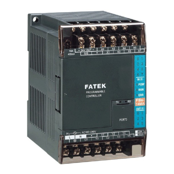
【 Hardware】 Chapter 1 Introduction of FATEK FB Series PLC The FATEK FB Series PLC is a new generation of micro PLC equipped with excellent functions comparable to medium or large PLC, with up to five communication ports. The maximum I/O numbers are 256 points for Digital Input (DI) and Digital Output (DO), 64 words for Numeric Input (NI) and Numeric Output (NO). -
Page 5: Appearance Of Expansion Unit/Module
○ Indicators for transmit (TX) and receive (RX) status of built-in communication port (Port0). ○ Indicator for Digital Input (Xn). ○ Indicator for Digital Output (Yn). ○ Indicator for system status (POW, RUN, ERR). ○ I/O output expansion header cover [units of 20 points or beyond only], with esthetic purpose and capable of securing expansion cable. - Page 6 Expansion unit/module with 60mm width case: [-16XY , -16Y , -20X ] ◇ ◇ I/O terminal block Output expansion Screw hole slot cover plate ψ × Output expansion slot Front view of output expansion slot with cover plate removed Output status indicator IN X OUT Y...
-
Page 7: Appearance Of Communication Expansion Module
Expansion module with 40mm width case: [ -24X, -24YT, -24YJ, -32DGI ] Output expansion slot Screw hole cover plate ψ × Front view of output expansion I I I2 slot with cover plate I8 I9 23 24 Input status IN X indicator FBs-24X Expansion cable... -
Page 8: List Of Fbs-Plc Models
List of FBs-PLC Models Module Name Specifications 6 points 24VDC digital input (2 points high speed 100KHz, 2 points medium speed 20KHz, 2 points FBs-10MA◇∆–◎–C medium speed total 5KHz); 4 points relay or transistor output (2 points high speed 100KHz, 2 points medium speed 20KHz);... - Page 9 Module Name Specifications Thumbwheel switch 8 sets 4 digits (total 32 digits) thumbwheel switch (or 128 points independent switch) multiplex input FBs-32DGI module, 30 pins header connector module 1 set 8 digits 7-segment/4 digits 16-segment LED display (or 64 points independent LED) output display FBs-7SG1 module, 16 pins header connector 16/7 Segment LED...
- Page 10 CARD-H FP-08 FBs- Series PLC handheld programmer Programming Devices FATEK-PLC Winproladder Programming software Winproladder FBs-PLC program memory pack with 20K Words program, 20K Words register, write protection switch Memory Pack FBs-PACK 10-bit single channel pulse width modulation(PWM) 0~10V analog output (AO) module...
-
Page 11: Specifications Of Main Unit
Specifications of Main Unit Item Specification Note Execution Speed 0.33uS/per Sequence Command Space of Control Program 20K Words Program Memory FLASH ROM or SRAM+Lithium battery for Back-up Sequence Command Application Command 326 (126 types) Include Derived Commands Flow Chart (SFC) Command Corresponding to External Digital Input Output Contact(DI) X0~X255 (256) -
Page 12: Environmental Specifications
1500Vp-p, width 1us Withstand Voltage 1500VAC, 1 minute L, N to any terminal Warning The listed environmental specifications are for FB -PLC under normal operation. Any operation in environment not conform to above conditions should be consulted with FATEK. H1-9... -
Page 13: Connection Diagrams Of Various Models
1.7 Connection Diagrams of Various Models 1.7.1 NC Control Main Unit [7.62mm Detachable Terminal Block] 20 point digital I/O main unit (12 points IN, 8 points OUT) 24V OUT max. 400mA -20MN Power ◇△ AC100~240V 24V OUT max. 400mA Power -20MN -D24/D12 ◇△... -
Page 14: Basic/Advanced Main Unit (Ma/Mc)
1.7.2 Basic/Advanced Main Unit [7.62mm Terminal Block, fixed in model MA, detachable in models MB/MC] 10 point digital I/O main unit (6 points IN, 4 points OUT) 14 point digital I/O main unit (8 points IN, 6 points OUT) 24V OUT 24V OUT max. - Page 15 32 point digital I/O main unit (20 points IN, 12 points OUT) 24V OUT max. 400mA -32MA ◇△ -32MB ◇△ Power -32MC ◇△ AC100~240V 24V OUT max. 400mA -32MA -D24/D12 ◇△ Power -32MB -D24/D12 ◇△ -32MC -D24/D12 ◇△ 24VDC / 12VDC 40 point digital I/O main unit (24 points IN, 16 points OUT) 24V OUT max.
-
Page 16: Digital I/O Expansion Unit
1.7.3 Digital I/O Expansion Unit [7.62mm fixed terminal block] 24 point I/O expansion unit (14 points IN, 10 points OUT) 24V OUT max. 400mA -24XY ◇ Power AC100~240V 24V OUT max. 400mA Power -24XY -D24/D12 ◇ 24VDC / 12VDC 40 point I/O expansion unit (24 points IN, 16 points OUT) 24V OUT max. -
Page 17: Digital I/O Expansion Module
1.7.4 Digital I/O Expansion Module [7.62mm fixed terminal block] 8 point digital I/O module (4 points IN, 4 points OUT) 8 point digital input module (8 points IN ) -8XY ◇ 8 point digital output module (8 points OUT) 16 point digital I/O module (8 points IN, 8 points OUT) ◇... -
Page 18: High-Density Digital I/O Expansion Module
1.7.5 High-Density Digital I/O Expansion Module [30Pin/2.54mm Header connector] 24 point high-density input module 24 point high-density transistor output module (24 points IN) (24 points OUT) -24YJ -24YT -24X S/S1 S/S2 S/S3 1.7.6 Numeric I/O Expansion Module [2.54mm Header connector] 7 segment LED display module Thumbwheel switch multiplex input module (4 digits ×... -
Page 19: Temperature Input Module
4 channel D/A output module 4 channel A/D input, 2 channel D/A output module -4A2D -4DA 1.7.8 Temperature Input Module [7.62mm fixed terminal block] 2/6 channel thermocouple input module 16 channel thermocouple input module -2TC -16TC T10+ T11+ T12+ T13+ T14+ T15+ T10-... -
Page 20: Expansion Power Module
1.7.9 Analog/Temperature Combo Module [7.62mm fixed terminal block] 2 channel A/D analog input & 4 channel 2 channel A/D analog input & 4 channel thermocouple input module RTD input module -2A4RTD -2A4TC 1.7.10 Expansion Power Module [7.62mm fixed terminal block] 24V OUT 24V OUT max. -
Page 21: Communication Module (Cm)
1.7.14 Communication Module (CM) [DB-9F connector/3Pin or 4Pin spring terminal block] 2 RS232 ports 2 RS485 ports FBs-CM22 FBs-CM55 1 RS232 + 1 RS485 ports 1 RS232 + 1 RS485 + Ethernet FBs-CM25 FBs-CM25E 2 RS485 ports + Ethernet RS232 RS485 /RS222 Converter 4 TX RS-232 to RS-485... -
Page 22: Communication Board (Cb)
RS485 Repeater GSM/GPRS RS485 HUB [7.62mm fixed terminal block] CH1+ GND2 GND1 CH2+ 4 ports RS485 HUB -CM5H RS-485 -CMGSM CH3+ GND4 Repeater COMMUNICATION GND3 CH4+ GSM MODULE FBs-CM5R 1.7.15 Communication Board (CB) [DB9F/3Pin spring terminal block](Below are outlooks of CB and the corresponding cover plates) 1 RS232 port 2 RS232 ports... -
Page 23: Analog Expansion Board
C ANopen PROGRAMMABLE CONTROLLER FBs-CBCAN CAN-H CAN-L FBs-CBCAN [5Pin European terminal block] 1.7.16 Analog Expansion Board 4 channel A/D analog input board 2 channel D/A analog output board PROGRAMMABLE PROGRAMMABLE CONTROLLER CONTROLLER VI0+ VI2+ VO0+ II0+ II2+ IO0+ VI1+ VI3+ VO1+ II1+ II3+... -
Page 24: Drawings With External Dimensions
1.8 Drawings with External Dimensions (1) Outlook I: Main Unit:FB -10M△, FB -14M△ Expansion Module:FB -16Y,FBs-16XY, FB -20X * (Main Unit and Expansion Module have the same type of base, with different top cover, as shown in the figure) PROGRAMMABLE CONTROLLER 2 - 4.5 units:mm... - Page 25 Outlook III: ○ 1 FB Expansion Module: -8X, FBs-8Y, FBs-8XY, FB -7SG1, FBs-7SG2, FB -6AD, FB -2DA, FB -4DA, -4A2D, FB -2TC, FB -6TC,FB -6RTD, FB -CM5H, FBs-2A4TC, FBs-2A4RTD, FBs-4PT, FBs-1LC, FBs-1HLC, FBs-6NTC, FBs-VOM ○ 2 FB -24X, FB -24YT, FBs-24YJ, FB -32DGI ○...
- Page 26 Outlook V: Programming Panel:FP-08 units:mm (6) Outlook VI: Data Access Panel:FB-DAP 17.6 9.98 H1-23...
- Page 27 (7) Outlook VII: 7-segment / 16-segment LED display board : D B . 5 6 - 8 R / D B . 8 - 8 R / D B 2 . 3 - 8 R / D B 4 . 0 - 4 R / D B A N . 8 - 4 R / D B A N 2 . 3 - 4 R 102.86 5.08 41.27...
- Page 28 364.46 78.53 12.98 78.18 12.98 78.18 12.98 78.63 ψ × D B4 .0-4R 79.8 33.91 6.03 33.90 2.97 D BAN .8- 4R 192.02 37.85 10.16 37.85 10.16 37.85 10.16 37.85 5.08 D BAN2 .3 -4R H1-25...
-
Page 29: Chapter 2 System Configuration
Chapter 2 System Configuration Single-Unit System of FB -PLC Intelligent Peripherals Digital I/O Expansion Unit/Module -24XY -40XY L o a d C e l l BASE -60XY Cell Phone -8XY Bar-code Reader Digital Input(DI) -16XY -1HLC -16Y SCADA -20X -CMGSM -24X -CM25E -24YT... -
Page 30: Formation Of Multi-Unit System
Regarding communication resources, the FBs-PLC hardware can accommodate up to 5 communication ports (with a maximum speed of 921.6Kbps). In addition to providing the standard FATEK communication protocol, it also supports the Modbus master/slave protocol or any user-defined protocol. This functionality easily renders the connections with intelligent peripherals such as electronic scale, bar code reader, and various meters and gauges. -
Page 31: Connection Of Fbs-Plc With Host Computer Or Intelligent Peripherals
Connection can be established as long as the upper-level computer or intelligent peripherals use either one of the two protocols. In the application, in which driver for FATEK or Modbus is not available, FATEK also provide standard DDE communication server, which enables FBs-PLC to connect with any computer system supporting DDE. -
Page 32: I/O Expansion
Chapter 3 Expansion of FB -PLC If the I/O point of the. Main unit of the applied FB -PLC is not enough for a specific application, then can expand it with the additional expansion units/modules. Besides I/O point there also have the requirements to expand the communication port in some occasions. - Page 33 on the main unit. Users can easily find each terminal with its I/O number and LED status indication, as shown in the figure below using X10 and Y6 as an example: 24V OUT max. 400mA I2 I3 IN X PROGRAMMABLE CONTROLLER OUT Y PORT0...
-
Page 34: Numeric I/O Expansion And I/O Channel Mapping
3.1.2 Numeric I/O Expansion and I/O Channel Mapping The numeric I/O in FBs-PLC treat 16 single-bit data as one 16-bit numeric data (Word) ranging from the 0~65535. Since all numeric data of FBs-PLC are stored in the register inside PLC (16-bit width), therefore numeric I/O is also called register I/O. - Page 35 VI0(V) The voltage and current inputs can’t II0(I) be used at the VI1(V) same time in the same channel. It II1(I) FBs-B2A1D only one (V or I) available. Both voltage and VO0(V) current will be outputted at the I O 0 ( I) same time.
-
Page 36: Expansion Of Communication Port
24V IN 24V IN FBs-32DGI 0 I 2 5V 10V IN X IN X OUT Y OUT Y FBs-7SG2 FBs-6AD FBs-2DA FBs-8XYR FBs-24MCR2-AC During the startup stage, FBs-PLC will automatically detect the types and CH numbers of expansion units/modules. While operation, the FBs-PLC will read the CH input values from the NI module and stores them into corresponding IR(R3804 ~ R3903) and outputs OR values (R3904~R3967) to channels on the NO module. - Page 37 2 RS232 (port3 & port4) communication modules FBs-CM22 2 RS485 (port3 & port4) communication modules FBs-CM55 1 RS232 (port3) + 1 RS485 (port4) communication expansion module FBs-CM25 1 RS232 (port3) + 1 RS485 (port4) communication module with Ethernet FBs-CM25E FBs-CM55E 1 RS485 (port3) + 1 RS485 (port4) communication module with Ethernet Communication boards, which can be directly installed on FBs main units, are employed for expansion of communication ports port1 and port2.
-
Page 38: Installation Environment
Chapter 4 Installation Guide Danger 1. Turn off all power during installation of FB -PLC or related equipments to prevent electric shock or damage to equipment. 2. Upon completion of all installation wiring, put the protective cover back on the terminal block before turning on the power to avoid electrical shock. -
Page 39: Ventilation Space
4.2.2 Ven tilation Sp ace The heat in FB -PLC is ventilated via air circulation. There should reserve more than 20mm space, both below and above PLC, and with vertical installation, for ventilation. as shown in the figure below: Heat ventilation Hanged max. -
Page 40: Fixation By Din Rail
4.3 Fixation by DIN RAIL In an environment with slight vibration (less than 0.5G), this is the most convenient way of fixation and is easy for maintenance. Please use DIN EN50022 DIN RAIL, as shown in the figure below. 35mm 1.0mm (1.38 in.) (0.039 in.) -
Page 41: Fixation By Screws
4.4 Fixation by Screws In environments with larger vibration (more than 0.5G), the unit must be secured by M3 or M4 screws. Positions and sizes of screw holes in various models of FB -PLC are illustrated in the following: 60mm 尺寸... - Page 42 尺寸 1750mm Size D: (6.890in) (0.157in) 90mm (3.543in) 2 - 4.5 (0.177 in) 21mm (0.827in) 40mm 尺寸 20mm Size E: (1.575in) (0.787in) 90mm (3.543in) 3.8mm (0.150in) 2 - 4.5 (0.177 in) 21mm (0.827in) 尺寸 25mm Size F: 3.8mm (0.984in) (0.150in) 90mm (3.543in) 2 - 4.5...
-
Page 43: Precautions On Construction And Wiring
4.5 Precautions on Construction and Wiring 1. During the wiring of FB –PLC, please follow local national standards or regulations for installation 2. Please choose the wires with proper wire gauge for I/O wiring according to the current loads. 3. Shorter wires are preferred. It is advised that the length of I/O wiring does not exceed 100m (10m for high-speed input). -
Page 44: Specifications And Wiring Of Ac Power Sourced Power Supply
Chapter 5 Power Supply Wiring, Power Consumption Calculation, and Power Sequence Requirements -PLC internally has three kinds of circuit: a 5VDC logic circuit, a 24VDC driver circuit (driver output devices, for example: relay, transistor, and etc), and a 24VDC input circuit. Only the 5VDC logic circuit and 24VDC output circuit are powered by the built-in power supply for main/expansion units or powered by expansion power supply modules (FBs-EPW-AC, FBs-EPW-D24), and the 24VDC input circuit can be choose to powered by the external power supply or the built-in power supply of main/expansion units or 24VDC sensor of FBs-EPW-AC/D12/D24. -
Page 45: Specifications And Wiring Of Dc Power Sourced Power Supply
:The 5VDC power of 10/14PTs main unit is generated from the 24VDC power in the output circuit, with specifications of Note * 5VDC±10% and 400mA (max) (Circuit is located on the I/O board of 10/14PTs main unit). :Without any I/O expansion interface, the 24VDC power in 10/14PTs main unit is for its output circuit alone and cannot be Note * used for other purposes. - Page 46 Model Sp e c . SPW14-D12/D24 SPW24-D12/D24 -EPW-D24 Item Rated Voltage 12 or 24VAC, -15%/+20% 24VAC, -15%/+20% Max. Power Consumption 21W / 14W 26W / 24W 21W / 14W Inrush Current 20A @ 12 or 24VDC 20A@24VDC <20ms Allowable Power Interrupt Fuse Spec.
-
Page 47: Residual Capacity Of Main/Expansion Unit
5.3 Residual Capacity of Main/Expansion Unit & Current Consumption of Expansion Module Besides its own circuits usage, the residual capacities of three sets of built-in power supply of main/expansion unit are big enough for other expansion modules usage. In addition, the expansion power (FB -EPW) module can also provides the power for expansion modules usage. -
Page 48: Maximum Current Consumption Of Expansion Module
7 1 0 m A To t a l 2 8 5 m A * F B S - 2 0 M N - D 2 4 6 7 0 m A To t a l 2 2 7 m A * F B S - 3 2 M N - D 2 4 6 2 7 m A To t a l 1 7 6 m A *... - Page 49 - FBs-2A4TC 39 mA 52 mA - FBs-2A4RTD 39 mA 32 mA - - FBs-B4AD 25 mA - - FBs-B2DA 223 mA - - FBs-B2A1D 158 mA Voice - - FBs-VOM 500 mA Output Module - FBs-4PT 25 mA 82 mA Special -...
-
Page 50: Calculation Example Of Power Capacity
5.3.3 Calculation Example of Power Capacity Power module selection is depending on the sum of current consumption of all modules. Therefore, user must know the current consumption of each module. Please refer to the above table, which has the maximum current consumption of each expansion module. - Page 51 R e s u l t : ( 1 ) F i r s t c a l c u l a t e c u r r e n t c o n s u m p t i o n o f i n t e r n a l 5 V D C l o g i c p o we r s u p p l y + 7 2 2 m A - 1 2 0 m A - 2 2 3 m A - 11 9 m A - 4 0 m A - 4 0 m A - 2 5 m A = + 1 5 5 m A ( O K ) ( 2 ) A n d t h e n c a l c u l a t e c u r r e n t c o n s u m p t i o n o f i n t e r n a l 2 4 V D C l o g i c p o we r s u p p l y + 3 2 5 m A - 1 2 4 m A - 1 3 6 m A - 1 3 6 m A = - 7 1 m A ( o v e r l o a d )
-
Page 52: Requirement Of Power Sequence In Main Unit And Expansion Unit/Module
5.4 Requirement of Power Sequence in Main Unit & Expansion Unit/Module When the power is on, the FB -PLC main unit first detects the type and number of expansion unit/module attached to its expansion interface and get the actual I/O configuration. Therefore, while the main unit performs detection, the power in expansion unit/module should be already UP, otherwise, the detected I/O configuration will not correct. -
Page 53: Specifications Of Digital Input (Di) Circuit
Chapter 6 Digital Input (DI) Circuit The FB -PLC provides the ultra high speed differential double end 5VDC inputs (i.e., single input with two terminals without common) and the single-end 24VDC inputs which use the common terminal to save terminals. The response speeds of single-end common input circuits are available in high, medium and low. -
Page 54: Structure And Wiring Of 5Vdc Ultra High Speed Differential Input Circuit
6.2 Structure and Wiring of 5VDC Ultra High Speed Differential Input Circuit Only the MN main unit of FBs provides the 5VDC ultra high speed differential input circuit, which is mainly used for the input of hardware high speed counter (HHSC) with a maximum working frequency up to 920 KHz. In practice, to ensure the high speed and high noise immunity, please use Line-Driver for differential line driving. -
Page 55: 24Vdc Single-End Input Circuit And Wiring For Sink/Source Input
6.3 24VDC Single-End Input Circuit and Wiring for SINK/SOURCE Input The 24VDC single-end digital input circuits of FB -PLC are available for high, medium and low speed. They all have the similar circuit structures but with different response speeds. To save input terminals, the circuit of single-end input is implemented by connecting one end of all input points (photo coupler) inside the PLC to the same internal common point labeled as S/S. -
Page 56: Chapter 7:Digital Output (Do) Circuit
Chapter 7 Digital Output (DO) Circuit The digital outputs of FB -PLC are available in the following two structures: the 5VDC ultra high speed Line-driver type differential output (i.e., one output occupying two terminals), and the single-end output circuit for saving terminals. There are three kinds of output device for the single-end output, which are relays, TRIAC and transistors. -
Page 57: Specifications Of Digital Output Circuit
7.1 Specifications of Digital Output Circuit Differential Single-End Transistor Output Item Output (T, J ) Single-End Relay Output Ultra High High Medium Specification Speed Speed Speed Speed Maximum output 920KHz 200KHz 20KHz For ON/OFF, not for frequent exchange ─ frequency* <250VAC, 30VDC Working Voltage 5VDC±10%... -
Page 58: 5Vdc Ultra High Speed Line-Driver Differential Output Circuit And Its Wiring
7.2 5VDC Ultra High Speed Line-Driver Differential Output Circuit and its Wiring The 5VDC ultra high speed Line-Driver differential output circuit of FB -PLC is only available for the main unit of the MN model. Its output can connect to general photo coupler circuit or Line-Receiver input circuit, with the connection shown in the figure below. -
Page 59: Structure And Wiring Of Single-End Transistor Sink & Source Output Circuit
- P L C AC/DC AC/DC AC/DC AC/DC 電源 電源 power power FUSE FUSE 動 作 次 數 萬 次 接點電流(A) Contact Current (A) 7.3.2 Structure and Wiring of Single-End Transistor SINK and SOURCE Output Circuit Transistor Single-End SINK Output -PLC FUSE FUSE... - Page 60 Transistor Single-End SOURCE Output -PLC FUSE FUSE power 電源 2PTs Common Output Block 4PTs Common Output Block 共點輸出區塊 共點輸出區塊 The figure above uses output block s of 2PTs common and 4PTs common as an example to explain the differences in structural and wiring for SINK and SOURCE output circuits, respectively.(8PTs common has the same block structure and wiring, except with different point number) The single-end SINK output and SOURCE transistor output in FB -PLC...
-
Page 61: Speed Up The Single-End Transistor Output Circuit (Only Applicable To High And Medium-Speed)
7.4 Speed up the Single-End Transistor Output Circuit (only applicable to high and medium-speed) Either with the SINK or SOURCE structure in single-end output transistor circuit, when the transistor switches from ON to OFF, the junction capacitor between transistor CE electrodes should be charged to near the load voltage VDD before it can stop the current running through the photocoupler inside the load, which increase the OFF time and decrease the response speed. - Page 62 A. Suppression of Surge Current Connect a small resistor R in series to lower the surge current, 以 but note that too large R will affect the driving capability or cause too much voltage drop. PLC output 輸出 relay 繼電器 Load Load 湧浪電流使接點熔化黏住...
-
Page 63: Protection Of Transistor Output And Noise Suppression
7.5.2 Protection of Transistor Output and Noise Suppression The transistor output in FB -PLC already includes Zener diode for counter-electromotive force, which is sufficient for low power inductive load and medium frequency of ON/OFF application. In conditions of high power or frequent ON/OFF, please construct another suppression circuit to lower noise interference and prevent voltage from exceeding the limit or overheating that may damage the transistor output circuit. -
Page 64: Chapter 8 Test Run, Monitoring And Maintenance
Chapter 8 Test Run, Monitoring and Maintenance Warning During maintenance, be sure to turn off the input power of PLC in case the actions to touch any terminal on PLC, or insert and extract accessories (e.g., expansion ribbon cables) is required. Otherwise, electric shock, short circuit, damaged PLC or PLC malfunction will be caused if the power is on. -
Page 65: Led Indications On Plc Main Unit And Troubleshooting
8.3 LED Indicators on PLC Main Unit and Troubleshooting 輸入狀態指示 "Xn" Input Status Indicator “Xn” 24V OUT max. 400mA 電源指示 "POW" Power Indicator “POW” Receive Indicator “RX” 接收指示 "RX" IN X 運轉指示 "RUN" Operation Indicator “RUN” PROGRAMMABLE CONTROLLER Transmit Indicator “TX” 傳送指示... - Page 66 are described in the following: Error Description Code Application program contains the functions not supported by this Mismatch of PLC ID VS. program ID Checksum error in LADDER program System STACK abnormal Watch-Dog occurs Exceed main unit I/O Syntax check error occurs Expansion I/O modules over limit Expansion I/O points over limit System FLASH ROM CRC error...
-
Page 67: Maintenance
2. Not overloaded, but Inrush current from capacitive load welds relay contacts at 〝 ON〞 , resulting in permanent ON, or burns transistor or TRIAC, resulting in permanent ON or OFF. 3. Not overloaded, but the inductive load without proper Snubber circuit causes high voltage sparks between relay contact at〝OFF〞and generate carbon deposition, which separates contacts and causes permanent OFF or intermittent ON/OFF, or punches through transistor or TRIAC with high voltage, resulting in permanent ON or OFF.
Need help?
Do you have a question about the FBs Series and is the answer not in the manual?
Questions and answers
Підключення сервопривода та інкодера