Table of Contents
Advertisement
Quick Links
- 1 Table of Contents
- 2 Ethernet Serial Interface
- 3 The Function of Ethernet Serial Converter
- 4 The Function of Serial Port Connectors
- 5 H a R D W a R E I N S Ta L L a T I O
- 6 D I P S W I T C H S E T T I N
- 7 Configuration Softw Are and Its Function
- 8 Configuration Thru Local Area Netw Ork
- Download this manual
Advertisement
Table of Contents

Related Manuals for FATEK FBs-CM25


Summary of Contents for FATEK FBs-CM25
- Page 1 FBs-CM25/CM55/CBE Ethernet Module User’s Manual Ve r. 2 . 1 Fatek Automation Corp. 7/1/2004 www.manasanat.ir...
-
Page 2: Table Of Contents
Preface ..................2 Specification . -
Page 3: Preface
To meet this trend, FATEK provides a series of Network interface modules, with which an economic and effective network solution for FATEK FBs-PLC can be obtained. -
Page 4: Ethernet Serial Interface
2.2 Ethernet Serial Interface Characteristics Description 1 0 B a s eT, I E E E 8 0 2 . 3 N e t w o r k I n t e r f a c e Tra n s m i s s i o n TC P, U D P, I P, A R P P r o t o c o l A p p l i c a t i o n P r o t o c o l... -
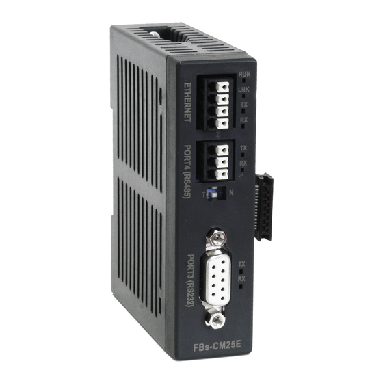
Page 5: Outline
3. Outline T h e o u t l i n e o f F B s - C M 2 5 E / C M 5 5 E m o d u l e i s s h o w n b e l o w FBs-CM25E FBs-CM55E a n d d e s c r i b e d a t f o l l o w :... -
Page 6: The Function Of Serial Port Connectors
4. The Function of Serial Port Connectors Port3 Connector: The signal level of Port3 connector is of RS232(CM25E) or RS485(CM55E). This port can be treated as a general communication port of CPU module and used for peripheral applications. Port4 Connector: The signal level of Port4 connector is of RS485(CM55E). -
Page 7: Application Architecture
5.1Application Architecture Base on the different requirements of network application this module provides two operating modes –Server Mode and Client Mode. When operates at server mode, the Ethernet module will wait for the message coming from the network. After decode the received message it will send the message thru serial port to the PLC main unit. - Page 8 The example illustrate on above is the simplest server mode application. Work station A and work station B are master that can send the command message actively to FBs-PLC, Upon receiving the command message, Ethernet module will send the message thru the port4 to FBs-PLC.
-
Page 9: Client Mode
When work at this mode, there is no need to write any program in PLC for operation. 5.1.2 Client Mode While work at client mode, the Ethernet module will wait the command message at port4. When it finds the message is for the PLC station located at remote site(Please refer section 5.3.6 for setting) then it will pack the message according to the content of port mapping table and send it to the network. - Page 10 network, the Ethernet module will perform the translation of message at the reverse order. First it will replace station number in message to the original station number and then re-calculate and update the check sum of message then send it to serial port. A standard client mode network application is shown as follows.
-
Page 11: H A R D W A R E I N S Ta L L A T I O
5 . 1 . 2 . 2 Vi r t u a l S e r ve r M o d e Though high security is the key feature of standard client mode, can’t accessed by other devices thru network is also a drawback. To take the balance between the security and connectivity, the Ethernet module provides a virtual server mode to meet the both end. -
Page 12: Cable Wiring
provides a jumper to disable the password protection temporary. This jumper can be accessed only when the module’s plastic cover is removed. The relative location of jumper is depicted at follow: NO PASS When the jumper cap of JP1 is at upper position (linked by white line), the password protection is disabled. -
Page 13: S O Ft W A R E C O N F I G U R A T I O
5.3 Softw are Configuration 5.3.1 Configuration Softw are and its Function ”Ether_cfg.exe” to aid the configuration of T h e r e i s a a c c o m pa n y s o ft w a r e Ethernet module. -
Page 14: Configuration Thru Local Area Netw Ork
Setup by Internet – With this method can setup the network configuration thru Internet. Most often is used to setup the station mapping or authorized IP. While use this method, can only setup one Ethernet module at a ti me and mus t specif y th e IP add ress of Et h ernet mod ule t o be edited . Considering the security, can set password to prevent the unintended access. -
Page 15: Co Mmo N Da Ta Setu
software - ether_cfg.exe. Use the mouse point to the ’Internet’ option buttons within the ’Configuration Channel’ group box and click it then the screen will be shown as below At this time can input the remote IP address of the Ethernet module desired for configuration. - Page 16 Protocol: There are two communication protocols were supported in this module. Modbus/TCP or Fatek. Modbus/TCP can be choosed only when the operation mode is set to Server mode while the Fatek mode can be used in both modes. Baud Rate(CM25E/CM55E): Communication speed between Ethernet module and PLC with 9600, 19200, 38400,57600,115200,230400 bps s i x options 。...
-
Page 17: S Ec Uri T Y Set U
enable the remote configuration to prevent the leakage of security hole. Please leave this option un-checked if remote configuration is not necessary. Import-Export button: Can use the Export function to save entire setup data of Ethernet module to file or use the Import function to retrieve the setup data stored in file to ease the editing job of configuration. - Page 18 Please input the new password at ’New Password’ and ’Confirm Password’ edit field and click the ’Change’ button to complete the setting of new password. Please click the ’Remove’ button if password protection is not necessary. The setting of access right- Use the setting of authorized IP to prevent the illegal access of data.
-
Page 19: Sta Ti O N & I P M A P P I N G S E T U
With this dialog to define a set of consecutive authorized IP addresses. Please input the first IP address of the consecutive IP addresses in the ’Grant IP’ field and input the size of IP addresses in ‘Group Size’ filed. 5.3.6 Station & IP mapping Setup This setting can only need to perform when Ethernet module is work at client mode. - Page 20 Move the cursor to the table locating in the center of window then click the right mouse button then the screen appears a pop-up menu as shown below Click ’Add’ to add one station mapping data. Click ’Del’ to delete a station mapping data.
-
Page 21: S E R V I C E P O R T S E T U
module can provide at most 19 groups of station mapping. 5.3.7 Service Port Setup T h e E t h e r n e t m o d u l e w h e n w o r k e i t h e r i n T C P o r U D P s e r v e r m o d e s h o u l d b e a s s i g n e d a s e r v i c e p o r t n u m b e r f o r c l i e n t a c c e s s . -
Page 22: Appendices
The communication protocol of FATEK TCP/UDP embeds the FATEK serial communication message in the TCP or UDP data packet. The port number used to convey the FATEK TCP/UDP message is configurable (default is 500, refer 5.3.7 for detail). Modbus/TCP Communication Protocol...
Need help?
Do you have a question about the FBs-CM25 and is the answer not in the manual?
Questions and answers