
Related Manuals for Kicker PRAMCQ09


Summary of Contents for Kicker PRAMCQ09
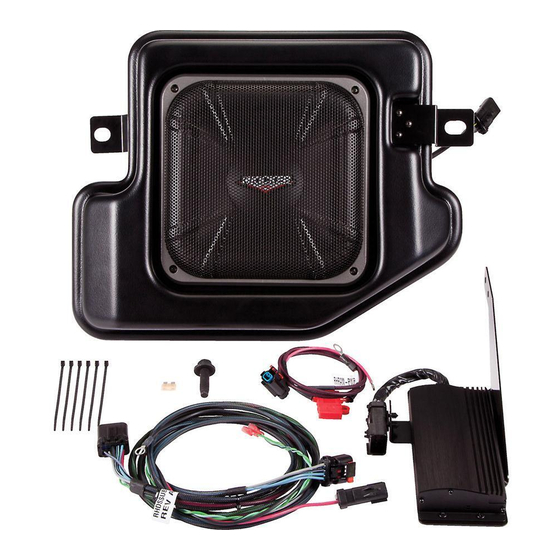
- Page 1 PRAMCQ09 ® Designed for 2009–2012 Dodge Ram vehicles Subwoofer Assembly Wire Ties x6 25A Fuse Power Harness Overlay Harness T-Taps x2 Amplifi er Seat bolt ©2012 Stillwater Designs PRAMCQ09-A3-20140729...
- Page 2 Amplifi er Assembly 7mm Screws x3 25A Fuse Wire Ties x6 Overlay Harness Power Harness...
- Page 3 1. Disconnect negative battery cable 2. Pull the rubber liner out of the storage tray on the dash and remove two Torx®T-20 screws. Fig. 1 3. Using a panel removal tool pry out on the plastic trim panel of the 110V AC plug and re- move it, if so equipped.
- Page 4 Fig. 6 Fig. 5 8. Using a panel removal tool gently pry up on the panel surrounding the shifter housing and remove. Fig. 7 9. Using a panel removal tool gently pry out on the radio trim bezel. Fig. 8 Fig.
- Page 5 13. Loosen and remove the nut on the positive battery accessory lug. Fig. 9 14. Connect the ring terminal of both power harnesses to the lug and retighten the nut. Torque to 14Nm. 15. Route the wires toward the rubber grommet on the fi re wall where the factory wiring harness passes through.
- Page 6 20. Plug the amplifi er harness into the amplifi er and install the amplifi er in the dash by sliding the two ¼” bolts on the amp bracket into the slotted holes on the dash support brace by the factory grounding point and then lining up the hole on the top of the bracket with the hole in the dash frame.
- Page 7 Subwoofer Harness Routing 28. Route the harness down the kick panel and along the bottom of the front door jam. Route the 10 pin connector under the front seat and out of the existing hole. Fig 17 29. Remove the two 8mm bolts holding the bracket for the seat wiring. Mount the amplifi er/ bracket assembly as shown in Fig 18 Fig.
- Page 8 33. Remove the 13mm and 10mm bolt on both sides of the bottom of the rear seat removed in step 26 and remove the storage cover. Fig. 21 34. Reinstall the seat and the back two 18mm bolts securing the seat. Tighten to 30ft/lbs. 35.
- Page 9 39. Route the harness along the bottom of the front and rear door jam. Route the harness behind the plastic sill plate and under the driver’s side rear, outermost seat bracket. Fig. 25 Fig. 25 40. Connect the four pin plug of the subwoofer harness to the subwoofer enclosure. Slide the red locking tab over to prevent the connectors from accidentally coming disconnected.
- Page 10 Troubleshooting the Kicker Integrated Systems If you experience a problem once the Subwoofer is installed, use this guide to locate the trouble. The radio is working, but the Subwoofer is not working: • Check the battery voltage to make sure it is not discharged below 11 volts.
- Page 11 Ground wire not grounded properly Check ground wire with voltmeter to insure it is a good ground Low battery voltage Recharge the battery If you continue to experience problems after troubleshooting, please contact KICKER Technical Support at (800) 256-0808 ext. 6009, or support@kicker.com.
- Page 12 stillwater designs P.O. Box 459 • Stillwater, Oklahoma 74076 • USA • (405) 624–8510...
Need help?
Do you have a question about the PRAMCQ09 and is the answer not in the manual?
Questions and answers