Delta DE212 Installation And Operation Manual
Hide thumbs
Also See for DE212:
- Operation and installation manual (36 pages) ,
- Operation and installation manual (17 pages) ,
- Installation manual (12 pages)
Table of Contents
Advertisement
Quick Links
Delta DE212
GLOBAL
System # 03040.
Wireless Deadman System
for Aero Plane Refuelling Trucks and Dispensers
For license-free, global operation.
Installation and operation Manual
- Approved transmitter
Delta RC AS
Tlf. +47 33 44 83 90
Document item no: 03039
P.O. Box 1065
Web site: www.deltarc.no
Revision No: D
NO-3204 Sandefjord
E-mail: hello@deltarc.no
Norway
Advertisement
Table of Contents

Subscribe to Our Youtube Channel
Related Manuals for Delta DE212


Summary of Contents for Delta DE212
- Page 1 Delta DE212 GLOBAL System # 03040. Wireless Deadman System for Aero Plane Refuelling Trucks and Dispensers For license-free, global operation. Installation and operation Manual - Approved transmitter Delta RC AS Tlf. +47 33 44 83 90 Document item no: 03039 P.O.
-
Page 2: Table Of Contents
Introduction............................12 3.2.2 Transmitter unit..........................12 Receiver unit ............................. 14 3.3.1 Hose rewind made easy with the DE212 wireless deadman ............15 3.3.2 Coding the transmitter and the receiver ................... 15 3.3.3 Operational requirements ......................... 15 SYSTEM COMPONENTS ..........................16 Standard delivery ............................. -
Page 3: Introduction
1. I NTRODUCTION The DE212 Global is the third generation of the Delta wireless Deadman control system, designed for aero plane refuelling trucks, hydrant dispensers and road trucks. The new system is designed with the latest technology to meet future demands and for trouble- free operation in an environment with heavy radio communication. -
Page 4: Installation
2. I NSTALLATION 2.1 Typical Receiver Installations The receiver unit is normally installed in the driver’s cabin, out of EX defined area. Before installing the receiver, it must be carefully considered the position inside the drivers cabin. On dispensers the receiver is often installed in the front of the cabin, using the standard antenna, like on photo 2 and 3. -
Page 5: Tank Truck Installation For Easy Access
Base stations to improve the 4G service for travellers entering or leaving the aircrafts at the gates. These 4G Base stations operates at a different frequency than the DE212, but at short range the much higher power can disturb the receiver input so much that the operation stability is reduced. -
Page 6: New Antenna Connector
Discontinued on standard deliveries 2.5 Antenna for external installation The DE212 system is always delivered with a standard antenna, for installation direct on the antenna connector on top of the receiver unit in the drivers cab. However if the standard solution does not give sufficient range and operational stability, an external antenna can be the solution. -
Page 7: External Antenna Position
In some areas of the airport the disturbing signals can be extremely strong, and a special antenna solution is needed. After several tests at different airports, Delta can offer a solution that is easy to install and effectively reduces the disturbing wireless signals and hence give the needed operational stability. -
Page 8: High Gain Sector Antenna. Installation Details
2.8 High gain sector antenna. Installation details. Art.no 11682 Sector antenna Art.no 03017 Antenna bracket For mast and wall 110° turnable 20° fixed tilt down Antenna face Art.no 12380 Connecting cable 5m With connectors Mast mount Wall mount See section 4, for article numbers and order information for spare parts and optional equipment. -
Page 9: Receiver Unit Connections
2.9 Receiver unit connections The new receiver mainboard with the added radio communication board, the HF- module. All external connections to the Deadman system are in the receiver unit. The in-and output signals are based on SW version: 02907. Connecting the receiver to the power source of the vehicle must be carefully considered. Normally the transmitter is stowed at the receiver for recharging the integrated battery. - Page 10 This function is always enabled Input signal. Stops all functions in the receiver when connected to GND Wired Deadman input, ON/OFF deadman or SW3-5. Optional. Contact Delta Failsafe distributor or Producer. GND, ground or common terminal. Same as P1-7 and P2-3 NOTES: •...
-
Page 11: Changing The Function Of The Receiver Unit By Dip Sw3
SW3-3: External override, enabled or disabled • -4: Differential Pressure Switch/ DP input at P3-2 enabled or disabled • -5: Wired Deadman input, P3-4. ON/OFF Deadman or Faisafe Delta Deadman Standard factory settings of switches: Default settings are shown Function Comments Deadman timer max 2min. -
Page 12: Operation
Receiver antenna for installation on top of the receiver. RP-SMA connector Optional: Antenna for external installation, omnidirectional, 360°with 3m cable. Sector antenna for installations with heavy radio disturbances Delta CH300, 115/ 230V mains-powered battery charger for transmitter, See section 4 for ordering information. RC AS Page 11 of 33... -
Page 13: Functional Description
A fully charged battery has a capacity of at least 12 hours of continues operation. The long operating time is made possible by the Delta timeshare transmission system, WTT. Using transmitting power only in very short periods. - Page 14 0C when not in use. Under normal operation, the battery lifetime is 2-4 years. New solution for transmitter moving handle and strap connection. 01958, Delta strap 01958, Delta strap for transmitter RC AS Page 13 of 33 ELTA Document no: 03039...
-
Page 15: Receiver Unit
3.3 Receiver unit Antenna Charge contacts Right Left Charge station CODE button CH, Charge, Yellow light ON, Green light NOTE: Drawings and Photos may differ slightly from reality. The receiver front has a charging station for the transmitter unit, two LED indicators and one push button marked “CODE”. -
Page 16: Hose Rewind Made Easy With The De212 Wireless Deadman
In order to make the receiver execute a function, the code in the handheld unit, the transmitter, must be transmitted to the receiver and correspond with the code stored in the receiver. The DE212 system has 65.536 different codes available. Each code and serial number of the unit is logged by the producer and used only once. -
Page 17: System Components
YSTEM COMPONENTS 4.1 Standard delivery Order number Item Description 03040 Remote Control DE212 Global Complete set, containing: Transmitter 02705, Receiver 03038 and Antenna 12376 Note : The standard delivery of a system has these main functions: • Timer controlled deadman. Running for 2 min. continuously. Warning light, or beeper tells operator 30 sec. -
Page 18: Receiver Front Unit, Part Identification
02704 Housing TX212-2S Global, ATEX/IECEx certified 02465 Battery module TX212 Global, ATEX/IECEx certified 02994 PCB RX212 Global mainboard G2 03014 PCB RX212 Global HF-module VX 01760 Housing RX212 Global Front 02999 Housing RX212 Global Bottom. 12375 Pigtail Cable RG316, 15cm. RP-SMA(f)- MCX(m) angle 12376 Antenna WiFi 2,4GHz 5dBi RP-SMA(m) 20cm long 01752... -
Page 19: Transmitter Part Identification
Ex requirements. To keep the classification, and the security, the TX212 unit should be inspected regularly by the user. In case of a damage of the TX212, it should be taken out of service send for repair to Delta RC AS or an appointed service station. -
Page 20: Battery Recharging
EX-certification, a new housing will require a new unit label, and this can only be issued if Delta RC gets a photo of the label of the defective housing. If this is not possible, the new housing must have a a new unit label. In addition Delta RC need the ser.no of the transmitter PCB and battery unit. -
Page 21: Replacing The Battery
This means that repair of the TX212 must take place at Delta RC AS or by a Delta RC AS appointed dealer. Otherwise EX- certificate may no longer be valid. - Page 22 WARNING: The battery replacement operation must always take place outside Ex-area. When the battery module has to be replaced, this procedure needs to be followed strictly: • Verify that the old battery module 02166 is replaced by 02465. Battery module 02465 must be replaced by 02465 only. •...
-
Page 23: Warranty Conditions
Packages being sent to and from Delta RC AS are in the responsibility of the purchaser, as he is also economically responsible for paying the transportation charges, toll, insurance and other charges related. -
Page 24: Distributors
P.O. Box 78 SE-43905 Åsa Sweden Phone: +46340655677 Fax +46340655677 E-mail: bewe@algonet.se Denmark Contact Delta RC for sales and service. E-mail: hello@deltarc.no Mexico Comantsup SA Paseo San Isidro 301-B Barrio de Santiaguito CP 52140 Metepec, Mexico Phone : +52 722 600 8800 Email : comantsup_sadecv@hotmail.com... -
Page 25: Distributors
Xiamen XINZ Mechanical Technology Co.,Ltd 醒志(厦门)机械科技有限公司 Room 1401, No. 1, B Block Hubian Garden Group 2 361011 XIAMEN China Phone: +86 158 5924 1578 salesxinz19@163.com E-mail: 7.2 Distributors France Marco Tech 5, Rue Jean Jaures FR-33310 Lormont France Phone: +33557306300 Fax: +33557306301 E-mail: info@marcotech.eu... - Page 26 54/116 Soi3. Baranee Village Klongsam. Klongluang, Pathum Thanee 12120 Bangkok Thailand Phone: +6628327253 Fax: +6625997662 E-mail: aviation_enterprise@yahoo.com Russia NSA Overseas LLC Avtozavodskaya str. 20 build. 1 115280, Moscow, Russia Mobile phone + 7 909 943 08 98 web: www.nsa-overseas.com Malaysia OGCF Engineering SDN BHD No.
-
Page 27: Technical Data
8. T ECHNICAL DATA 8.1 General This equipment complies with the following standards: Europe/EU: ERC 70-03 EN 300-400. USA: FCC 15.249. Japan: STD-T66. It is in accordance to EU’s demands in order to label the equipment with CE. Transmitters are ATEX/IECEx approved, according to: EN 50 014:1997+A1+A2. EN 50 020:2013 and For the EU : II 2 G Ex ib IIC T4, EN 60079-0:2012 + A11:2013 and EN 60079-11:2012 IECEx: IEC 60079-0 Ed.6 and IEC 60079-11 :2011... -
Page 28: Receiver
8.3 Receiver Antenna: 2,4GHz 5dBi gain, RP-SMA male connector. 20cm long Antenna connector: RP-SMA connector on receiver top. Power Supply: 11 to 27 V DC. Voltage above 35VDC shuts down the receiver. Power Consumption: Standby: 50mA. During max charging: 100mA. Connections: Screw terminal on PCB connectors. -
Page 29: Dimensions
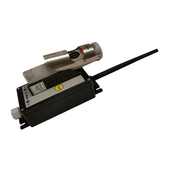
8.4 Dimensions 8.4.1 Receiver with transmitter stowed. All dimensions in mm. NOTE: The length of the antenna may change due to general development, and hence the total hight of the receiver. RC AS Page 28 of 33 ELTA Document no: 03039... -
Page 30: Transmitter Unit
8.4.2 Transmitter unit All dimensions in mm. RC AS Page 29 of 33 ELTA Document no: 03039... -
Page 31: Certificates
9. C ERTIFICATES 9.1 Transmitter Ex Certificate RC AS Page 30 of 33 ELTA Document no: 03039... -
Page 32: Declaration Of Conformity
9.2 Declaration of conformity For further information, please contact Delta RC: hello@deltarc.no RC AS Page 31 of 33 ELTA Document no: 03039... -
Page 33: Environmental Information
10. E NVIRONMENTAL INFORMATION Care has been taken while producing this units, to ensure that all excess materials are disposed properly, and recycled accordingly. Please help us with this process in the future. This means: Do not dispose this devices into the trash when discarding. To minimize pollution and ensure environment protection, please recycle properly, to ensure the smallest possible environmental footprint. -
Page 34: Delta Rc As
Norway www.deltarc.no Delta RC AS reserves the right to make changes without further notice to the product, to improve reliability, functions, and design. Delta RC AS does not assume any liability arising out of the application or use of the product if not used strictly according to the regulations described in this document.
Need help?
Do you have a question about the DE212 and is the answer not in the manual?
Questions and answers