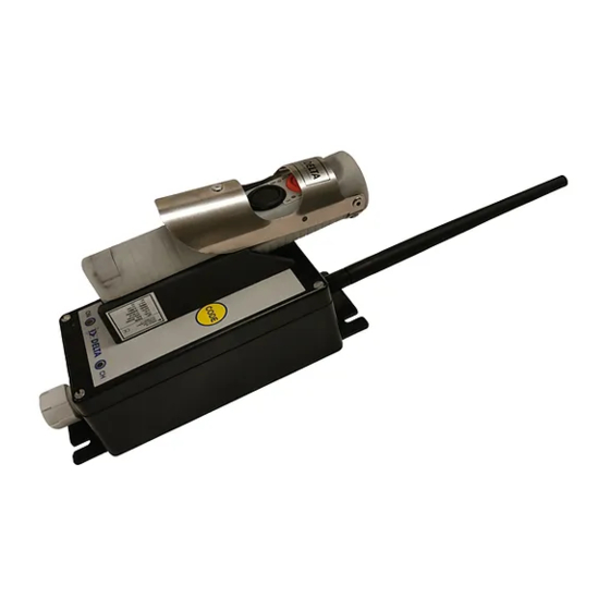
Delta DE212 Operation And Installation Manual
Failsafe, wired deadman control for aero plane refuelling trucks and dispensers
Hide thumbs
Also See for DE212:
- Operation and installation manual (36 pages) ,
- Installation and operation manual (34 pages) ,
- Installation manual (12 pages)
Table of Contents
Advertisement
Quick Links
Delta DE212
Failsafe, Wired Deadman Control
for Aero Plane Refuelling Trucks and Dispensers
Operation and Installation Manual
Delta RC AS
Tlf. +47 33 44 83 90
Document item no: 02002
P.O. Box 1065
Søndre Kullerød 4A
Web site: www.deltarc.no
Last revision: 18.08.2017
N-3204 Sandefjord
E-mail: hello@deltarc.no
Norway
Advertisement
Table of Contents

Subscribe to Our Youtube Channel
Summary of Contents for Delta DE212
- Page 1 Delta DE212 Failsafe, Wired Deadman Control for Aero Plane Refuelling Trucks and Dispensers Operation and Installation Manual Delta RC AS Tlf. +47 33 44 83 90 Document item no: 02002 P.O. Box 1065 Søndre Kullerød 4A Web site: www.deltarc.no Last revision: 18.08.2017 N-3204 Sandefjord E-mail: hello@deltarc.no...
-
Page 2: Table Of Contents
User and Installation Manual for DE212-1S Wired Deadman Contents INTRODUCTION ..............................3 ..............................3 YSTEM DIAGRAM INSTALLATION ..............................4 , CU212-1S C ......................4 ONTROL ONNECTIONS SW2........................... 5 HANGE OF FUNCTIONS BY ..........................6 NSTALLING THE ONTROL ......................... 6 ABLE CONNECTION TO HANDHELD UNIT OPERATION .............................. -
Page 3: Introduction
"emergency-stop" the refuelling from a remote position. The DE212 has a built in timer system, with timeout warning outputs for light and beeper. The standard timer is set to 2 minutes with the warning signals 30 seconds before the refuelling will shut down. -
Page 4: Installation
User and Installation Manual for DE212-1S Wired Deadman 2. I NSTALLATION , CU212-1S C ONTROL ONNECTIONS The power supply can be 12 or 24VDC, and is connected as described. See figure below. Connections to the in the control unit. SW2 see notes below, chapter 2.2... -
Page 5: Change Of Functions By Sw2
User and Installation Manual for DE212-1S Wired Deadman NOTES: • Input voltage should be 12 or 24VDC. Max 35VDC • All outputs gives 12/24V out when activated, max 3,5A per output, total load: 5A. • Note that the potential between the minus pole and ground/GND, must not be greater than 50VDC/AC peak. -
Page 6: Installing The Control Unit
User and Installation Manual for DE212-1S Wired Deadman NSTALLING THE ONTROL The control unit should normally be placed in the drivers cabin. It must not be installed in EX area. Make sure that the control unit is easy accessible for service. -
Page 7: Operation
User and Installation Manual for DE212-1S Wired Deadman 3. O PERATION ESCRIPTION System Diagram CU212-1S CB212-1S Input signals Power and output signals Junction box. ( Optional.) The complete system consists of the following parts: • CU212-1S, control unit for installation in the drivers cabin. -
Page 8: Function Description
User and Installation Manual for DE212-1S Wired Deadman UNCTION ESCRIPTION CB212-1S, Handheld unit. Deadman handle STOP button Deadman button Cable strain relief The functions of the handheld unit, CB212-1S, is controlled by electronic circuits at the printed circuit board inside the housing. The handheld unit has two push buttons, one black and one red. The black is the deadmans button, which can be operated by the lever or the directly to push the button. - Page 9 User and Installation Manual for DE212-1S Wired Deadman CU212-1S, Control unit: CODE button External connections CH LED ON LED The front panel has two light diodes, LED's on the front panel. One is marked ON, and the other is marked CH.
-
Page 10: Maintenance
User and Installation Manual for DE212-1S Wired Deadman AINTENANCE This equipment should be kept as clean as possible at all times. Physical damages that may result in cracks or holes on the cabinets should be repaired as soon as possible by competent personal. -
Page 11: Warranty Conditions
The guaranty ceases 12 months after the delivery date. Delta RC AS AS or appointed repair workshop, is bound to repair and replace defect parts in its products, free of charge, in its main workshop during its normal working hours. Packages being sent to and from Delta RC AS are in the responsibility of the purchaser, as he is also economically responsible for paying the transportation charges, toll, insurance and other related charges. -
Page 12: Technical Data
User and Installation Manual for DE212-1S Wired Deadman ECHNICAL This equipment is designed for failsafe operation, meeting the stringent requirements for safe operation. It is in accordance to EU’s demands to CE-label the equipment. ENERAL PECIFICATION * Temperature Range: Operational and storage: -25 to +65º C. -
Page 13: Dimensions
User and Installation Manual for DE212-1S Wired Deadman IMENSIONS 6.4.1Control Unit All dimensions in mm. RCS AS Page 13 of 17 ELTA Document: 02002... -
Page 14: 6.4.2 Handswitch
User and Installation Manual for DE212-1S Wired Deadman 6.4.2 Handswitch All dimensions in mm. RCS AS Page 14 of 17 ELTA Document: 02002... -
Page 15: 6.4.3 Wall-Mount For Handswitch
User and Installation Manual for DE212-1S Wired Deadman 6.4.3 Wall-mount for Handswitch All dimensions in mm. Delta RC AS AS reserves the right to change the specifications and upgrade its products without any previous written notice. RCS AS Page 15 of 17... -
Page 16: Environmental Information
User and Installation Manual for DE212-1S Wired Deadman 7. E NVIRONMENTAL INFORMATION Care has been taken while producing this units, to ensure that all excess materials are disposed properly, and recycled accordingly. Please help us with this process in the future. - Page 17 Delta RC AS reserves the right to make changes without further notice to the product, to improve reliability, functions and design. Delta RC AS does not assume any liability arising out of the application or use of the product if used according to this document.


Need help?
Do you have a question about the DE212 and is the answer not in the manual?
Questions and answers