Lippert Ground Control 3.0 Installation And Owner's Manual
5th wheel leveling prepped unit to full automatic leveling
Hide thumbs
Also See for Ground Control 3.0:
- Installation manual (18 pages) ,
- Owner's manual (8 pages)
Table of Contents
Advertisement
Quick Links
Table of Contents
. . . . . . . . . . . . . . . . . . . . . . . . . . . . . . . . . . . . . . . . . . . .
. . . . . . . . . . . . . . . . . . . . . . . . . . . . . . . . . . . . . . . . . . . .
. . . . . . . . . . . . . . . . . . . . . . . . . . . . . . . . . . . . . . . . . . . . . . . . . . .
. . . . . . . . . . . . . . . . . . . . . . . . . . . . . . . . . . . . . . . . . . . . . . . .
. . . . . . . . . . . . . . . . . . . . . . . . . . . . . . . . . . . . . . . . . . . . .
. . . . . . . . . . . . . . . . . . . . . . . . . . . . . . . . . . . . . . . . . . . . . .
lippert.com
432-LIPPERT (432-547-7378)
. . . . . . . . . . . . . . . . . . . . . . . . . . . . . . . . . . .
. . . . . . . . . . . . . . . . . . . . .
. . . . . . . . . . . .
. . . . . . . . . . . . . . . . . . . . . . . . . . . . .
. . . . . . . . . . . . . . . . . . . . . . . . . . . . . . .
. . . . . . . . . . . . . . . . . . . . . . . . . . . . .
. . . . . . . . . . . . . . . . . . . . . . . . . . . . . . . . . .
. . . . . . . . . . . . . .
Ground Control
5th Wheel Leveling Prepped Unit
to Full Automatic Leveling
Installation and Owner's Manual
(For Aftermarket Applications)
Ground Control
5th Wheel Leveling Prepped
Unit to Full Automatic Leveling
Installation and
Owner's Manual
(For Aftermarket Applications)
Part #
Part #
2021106810
2
2
2
3
3
4
4
5
5
5
6
8
9
10
. . . . . . .
. . . . . . . . . . . . . . . . . . . . . . . . . . . . . . . . . . . . . . . . . . . . . . . . . .
11
1
Ground Control 3.0 Aftermarket Kit
Ground Control 3.0 Aftermarket Kit
Description
Description
Conversion to Full Ground Control 3.0
5th Wheel LCD Leveling System
. . . . . . . . . . . . . . . . . . . . . . . . . . . . . . . . . . . . . . . . . . . . .
. . . . . . . . . . . . . . . . . . . . . . . . . . . . . . . . . . . .
. . . . . . . . . . . . . . . . . . . . . . . . . . . . . . . . . .
. . . . . . . . . . . . . . . . . . . . . . . . . . . . . . . .
. . . . . . . . . . . . . . . . . . . . . . . . . . . . . . . . . . . . . . . . . . .
. . . . . . . . . . . . . . . . . . . . . . . . . . . . . . . .
. . . . . . . . . . . . . . . . . . . . . . . . . . . . . . . . . . . .
. . . . . . . . . . . . . . . . . . . . . . . . . . . . . . . . . . . . . .
. . . . . . . . . . . . . . . . . . . . . . . . . . . . . . . . . . . . .
. . . . . . . . . . . . . . . . . . . . . . . . . . . .
. . . . . . . . . . . . . . . . . . . . . . .
. . . . . . . . . . . . . . . . . . . . . . . . . . . . . . . . . . . . . . . . .
. . . . . . . . . . . . . . . . . . . . . . . . . . . . . . . . . . . .
. . . . . . . . . . . . . . . . . . . . . . . . . . . . . . . . . . . . . . .
CCD-0004397
®
3.0
3.0
®
12
12
12
13
13
. . . . . . . . . . . . . . . . . . . . . .
14
14
15
15
15
16
17
17
18
19
20
Rev: 10.14.21
Advertisement
Table of Contents

Related Manuals for Lippert Ground Control 3.0


Summary of Contents for Lippert Ground Control 3.0
-
Page 1: Table Of Contents
Ground Control 3.0 Aftermarket Kit Ground Control 3.0 Aftermarket Kit Part # Part # Description Description Conversion to Full Ground Control 3.0 2021106810 5th Wheel LCD Leveling System Table of Contents Operation Introduction .......... -
Page 2: Introduction
Installation and Owner’s Manual (For Aftermarket Applications) Introduction Safety Ground Control 3.0 is an intelligently-designed system Read and fully understand all instructions before installing that includes leveling jacks driven by the power of Hall or operating this product. Adhere to all safety labels. -
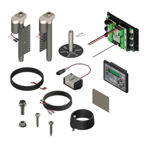
Page 3: Parts List
NOTE: Part numbers are shown for identification purposes only. Not all parts are available for individual sale. All parts with a link to the Lippert Store can be purchased. Ground Control 3.0 5th Wheel Leveling Prepped to Ground Control 3.0 5th Wheel Leveling Prepped to... -
Page 4: Preparation
This area is outlined in a green dotted line (Fig. 2A). 4. Make sure coach is on a solid level surface and is level from front to back before proceeding with installation. Fig.2 lippert.com 432-LIPPERT (432-547-7378) CCD-0004397 Rev: 10.14.21... -
Page 5: Measuring Approach And Departure Angle
4. Connect the jack motor wires (Fig.6A) to the jack wire 2. Tighten the bolts to 90ft-lbs of torque. harnesses (Fig.6B) from the chassis for all four jacks. NOTE: Lippert recommends zip-tying the wire harnesses tight against the rear jack motors to prevent damage to the wire harnesses. -
Page 6: Rear Sensor Installation
Mark on the plate where the rear sensor will set. Space location of the rear sensor installation from step 1. between the sensor and the crossmember MUST be left so the wire harness will not be pinched. Fig.10 Fig.8 lippert.com 432-LIPPERT (432-547-7378) CCD-0004397 Rev: 10.14.21... - Page 7 Fig.14 7. Push any slack in the rear sensor harness (Fig.14B) and connection of the rear sensor (Fig.14A) back through the slit in the underbelly (Fig.14C). Fig.12 lippert.com 432-LIPPERT (432-547-7378) CCD-0004397 Rev: 10.14.21...
-
Page 8: Lcd Touchpad Installation
A. Unplug all harnesses from the back of the switch (Fig.15B or 16A). B. Disconnect the switch panel’s power wires from the 30 amp circuit breaker (Fig.16B) and ground from the grounding source (Fig.16C). Fig.16 Fig.18 lippert.com 432-LIPPERT (432-547-7378) CCD-0004397 Rev: 10.14.21... -
Page 9: Controller Installation
The controller must be positioned directly in the center of the trailer with the arrow on the label of the controller facing the front of the trailer. (Fig.21). compartment ceiling Fig.19 front of trailer Fig.20 Fig.21 lippert.com 432-LIPPERT (432-547-7378) CCD-0004397 Rev: 10.14.21... -
Page 10: Front Landing Gear Wire Harness Installation
9’ power wire harness. NOTE: Be sure to properly scrape away any paint on a metal surface where ground is made. 4. Connect all jack harnesses to the appropriate connectors on the controller. lippert.com 432-LIPPERT (432-547-7378) CCD-0004397 Rev: 10.14.21... -
Page 11: Zero Point Calibration - Initial Setting
See Basic Jack Operation, for instructions on how to manually operate the system. 3. To set the current position as the zero point, press the ENTER button (Fig.28C). 4. LCD display will read, Zero point stability check (Fig.25). Fig.25 lippert.com 432-LIPPERT (432-547-7378) CCD-0004397 Rev: 10.14.21... -
Page 12: Operation
3. Make sure battery(ies) are fully charged and test at WHICH IT IS INTENDED IS PROHIBITED BY 12+VDC under load. LIPPERT’S LIMITED WARRANTY. THE LIPPERT LEVELING SYSTEM IS DESIGNED AS A LEVELING Touch Pad Diagram SYSTEM ONLY AND SHOULD NOT BE USED TO... -
Page 13: Basic Jack Operation
3. Red indicator lights (Fig.30C) may come on, indicating the current disposition of the trailer. In this case, the front and right sides of the trailer are low. lippert.com 432-LIPPERT (432-547-7378) CCD-0004397 Rev: 10.14.21... -
Page 14: Auto Level
4. A side to side leveling sequence will occur. 5. The LCD display will read, AUTO LEVEL SUCCESS (Fig.31) and then proceed to finish stabilizing the unit. Fig.31 lippert.com 432-LIPPERT (432-547-7378) CCD-0004397 Rev: 10.14.21... -
Page 15: Hitch Recognition
1. Find the port on the top of the jack motor (Fig.34A). 2. Remove the rubber plug (Fig.35A). ” drive into the port (Fig.36A). 3. Insert the 4. Turn override until the jack extends or retracts to desired position. Fig.33 Fig.35 Fig.34 Fig.36 lippert.com 432-LIPPERT (432-547-7378) CCD-0004397 Rev: 10.14.21... -
Page 16: Special Jack Error Codes
A. Press, FRONT (Fig. 28G) to operate both front jacks. B. Press, REAR (Fig. 28J) to operate both rear jacks. C. Press, LEFT and RIGHT (Fig. 28H and Fig. 28I) simultaneously to operate both middle jacks. lippert.com 432-LIPPERT (432-547-7378) CCD-0004397 Rev: 10.14.21... -
Page 17: Zero Point Calibration - Reset
5. To set the current position as the zero point, press the ENTER button (Fig.28C). 6. LCD display will read, Zero point stability check (Fig.42). Fig.42 7. LCD display will read, Zero point set successfully, once process is complete (Fig.43). Fig.43 lippert.com 432-LIPPERT (432-547-7378) CCD-0004397 Rev: 10.14.21... -
Page 18: Lcd Error Codes
Function Aborted during an automatic operation. pressing any buttons on the touch pad. ***ERROR**** Short circuit detected in one of the hall effect circuits. Test for short. Repair or replace as needed. Hall Effect Short lippert.com 432-LIPPERT (432-547-7378) CCD-0004397 Rev: 10.14.21... -
Page 19: Wiring Diagram
Rear Jack Rear Jack Harness Harness Mid Jack Mid Jack Harness Harness 6 Point Green Controller Prepped Wire Right Left Middle Middle Jack Jack 50 Amp Circuit Breaker Battery Left Right Rear Rear Jack Jack lippert.com 432-LIPPERT (432-547-7378) CCD-0004397 Rev: 10.14.21... -
Page 20: Notes
Installation and Owner’s Manual (For Aftermarket Applications) Notes Manual information may be distributed as a complete document only, unless Lippert provides explicit consent to distribute individual parts. All manual information is subject to change without notice. Revised editions will be available for free download at lippert.com.
Need help?
Do you have a question about the Ground Control 3.0 and is the answer not in the manual?
Questions and answers