Table of Contents
Advertisement
Advertisement
Table of Contents

Subscribe to Our Youtube Channel
Related Manuals for Lippert SlimRack


Summary of Contents for Lippert SlimRack
- Page 1 SlimRack Slide-Out OWNER'S MANUAL ®...
-
Page 2: Table Of Contents
Notes Introduction The Lippert SlimRack® Slide-Out system maximizes interior RV space by providing added comfort and offering a practical solution for additional space needs. The Lippert SlimRack Slide-Out system combines versatile above-floor placement with attractive, seamless flush-floor style for a sleek, polished, high-end look with no step up. -
Page 3: Product Information
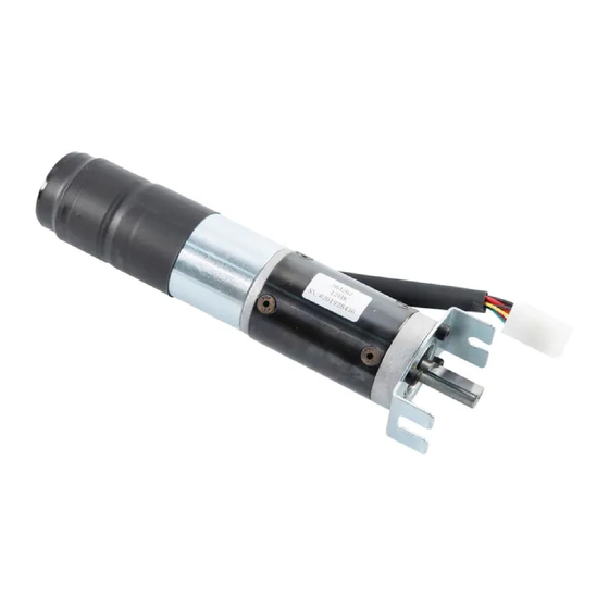
Product Information The Lippert SlimRack Slide-Out system is a rack-and-pinion design operated by a 12V DC gear motor. Slide- out systems are engineered to provide years of trouble-free service. Changes to weight, stroke, weight distribution, gear rack position, controller, power supply seals, slide toppers, ramps, rollers, etc., all have an effect on the performance of the system. - Page 4 There are two types of brackets used for fastening the motor and block assembly. Effective early February, 2018, the bracket used for the spring and hook attachment (Figs. 4 and 5) between the motor and the block was replaced with a new bracket and retention screw (Figs. 6 and 7). Fig.
-
Page 5: Component Descriptions
• A manual override that allows extension / retraction of the slide-out room in the event of a loss of power. • Floor rollers (not supplied by Lippert ) that support the slide-out room's weight while extending and retracting the slide-out room. Only floor rollers approved by Lippert can be used with the system. Contact Lippert for recommended rollers. -
Page 6: Safety
Safety The “WARNING” symbol above is a sign that an procedure has a safety risk involved and may cause death or serious injury if not performed safely and within the parameters set forth in this manual. Always wear eye protection when performing this procedure. Other safety equipment to consider would be hearing protection, gloves, and possibly a full face shield, depending on the nature of the procedure. -
Page 7: Operation
Operation Always make sure that the slide-out room path is clear of people, pets and objects before and during operation of the slide-out. Always keep away from the gear racks when the slide-out room is being operated. Obstructions in the slide-out room's path can cause serious personal injury, severe product or property damage . -
Page 8: Troubleshooting
Preparation Resources Required • 1-2 people, depending on task • 3" extension for sockets • Phillips head screwdriver • " deep well socket • Pick tool • 12V DC power source • Ratchet or socket wrench • Multimeter 5/16 • "... - Page 9 Fault Code Table - Programmable 1510000199 / 366697 Fault Fault Code Description Why? What Should Be Done? Type (# of RED flashes) Stops have not been set Stops not Stops must be programmed by an Major Stops were cleared programmed authorized service facility.
- Page 10 Programmed • Stops were improperly set document. Minor Fuse, Motor 1 Motor fuse concern Contact Lippert Representative Battery dropped below 8.5V Battery Drop Charge battery, start vehicle, generator, or Major while extending or retracting make sure unit is pugged into shore power.
-
Page 11: Auto-Programmable Controllers
Auto-Programmable Controllers Auto-programmable controllers, 1510000236 / 366701 697096, 700156, or 1510000276 / 366703 (Winnebago), which connect to a rocker switch, have the ability to detect and display several faults. When a fault is detected, the slide-out room movement may stop and two different LEDs on the controller will flash in a pattern. - Page 12 SlimRack Systems 82-S0533. If necessary, copy and paste or type the Bad wire connection. following path into a browser; https:// www.lci1.com/slide-outs-/support- Motor 2 slimrack then look for the specified Major fault Bad motor. document among the listing. Consult manufacturer of...
- Page 13 Refer to Technical Information Sheets: Motor 1 Major Troubleshooting Control Box for fault Bad motor. SlimRack Systems 82-S0533. If necessary, copy and paste or type the following Bad wire connection. path into a browser; https://www.lci1. Motor 2 com/slide-outs-/support-slimrack then Major...
-
Page 14: Electrical Override Modes
Electrical Override Modes Manual-Program Motorized or Towable Controllers In the event of component failure, the slide-out room operation can be overridden and retracted for travel. Use this procedure when there is NO loss of power or electrical problem with the system. Using a Phillips head screwdriver, remove the touchpad from the wall. -
Page 15: Auto-Programmable Controllers
NOTE: At any time during the override procedure, the unit will exit the override mode if the slide-out room has not been moved for two minutes or if a fault is detected during slide-out room movement. The Fault Code and Room or Lock Movement LEDs on the front of the touchpad will flash rapidly for 10 seconds to indicate that the override procedure failed. -
Page 16: Manual Override Mode-All Controllers
Manual Override Mode—All Controllers In the event that power is lost to the slide-out motor(s) or when the Electrical Override Mode does not work, the slide-out room can be manually retracted by following these steps. When manually retracting the slide-out room, make sure that both sides of the slide-out room move together. -
Page 17: Alternate Override Modes-All Controllers
Alternate Override Modes—All Controllers If none of the previous override methods retract the slide-out room, it may be possible to manually retract the slide-out room by one of the following alternate methods. Both of these procedures will only be possible if there is access to the described areas. Manually retract the slide-out room using a ratchet and socket attached to the end of the coupler (Fig. - Page 18 D. Once the slide-out room is retracted, secure the slide-out room in-place by: Re-installing the motors. If there is a retaining spring, make sure the end of the retaining spring is re-hooked to the motor spring clip (Fig. 20). With the motor retainer fully engage, tighten the motor retaining screw, until resistance is felt on the wrench.
-
Page 19: Maintenance
Maintenance The Lippert Slide-Out system has been designed to require very little maintenance. To ensure the long life of the Slide-Out system, read and follow these simple procedures: When slide-out room is extended, visually inspect the slide gear rack assemblies. Check for excess buildup of dirt or other foreign material. -
Page 20: Wiring Diagram For Controller 1510000199 / 366697
Wiring Diagram for Controller 1510000199 / 366697 Touchpad Switch Harness Power Harness Controller Controller-to-Motor Harness Wiring Diagram for Controller 700155/700157 Power Harness Controller Canbus Data Harnesess Park Brake Harness Controller-to-Motor Harness Controller 700155 does not have a parking brake input Touchpad Switch Page 20 Rev: 01.07.22... -
Page 21: Wiring Diagram For Controller 1510000236 / 366701 ,697096, 700156
Fault Code LED Power Switch Power Yellow Switch Out Blue Switch In NOTE: If the slide-out operation rocker switch is not supplied by Lippert Components, the gray wire on the 4-wire switch harness is not used. Page 21 Rev: 01.07.22 CCD-0001459... -
Page 22: Wiring Diagram For Controller 1510000276 / 366703 (Wgo - Discontinued)
Fault Code LED Power Switch Power Yellow Switch Out Blue Switch In NOTE: If the slide-out operation rocker switch is not supplied by Lippert Components, the gray wire on the 4-wire switch harness is not used. Page 22 Rev: 01.07.22 CCD-0001459... -
Page 23: Notes
Lippert part number 366697 ,700155, 700157 and document 30100002814, Rev 0F issued December 2014 for auto-programmable controller part numbers (Power Gear / Lippert) 1510000236 / 366701 697096, 700156 and 1510000276 / 366703 (Winnebago). All information has been updated to current practices. - Page 24 The contents of this manual are proprietary and copyright protected by Lippert Components, Inc. (LCI). Lippert prohibits the copying or dissemination of portions of this manual unless prior written consent from an authorized Lippert representative has been provided. Any unauthorized use shall void any applicable warranty. ...
Need help?
Do you have a question about the SlimRack and is the answer not in the manual?
Questions and answers
What brand of “dry lubricant” do you recommend?