GEZE ECturn Inside Installation And Service Instructions Manual
Hide thumbs
Also See for ECturn Inside:
- Installation and service instructions manual (32 pages) ,
- Original operating instructions (20 pages) ,
- Wiring diagram (44 pages)
Table of Contents
Advertisement
Quick Links
Advertisement
Table of Contents

Related Manuals for GEZE ECturn Inside


Summary of Contents for GEZE ECturn Inside
- Page 1 ECturn Inside EN Installation and service instructions 150647-01...
-
Page 2: Table Of Contents
ECturn Inside Contents Symbols and illustrations ..............................3 Product liability ..................................3 Reference documents ................................3 Safety ...................................3 Intended use........................................3 Safety notices ........................................4 Safety-conscious working .....................................4 Inspection of the installed system ................................4 Environmentally conscious working .................................4 Disposal ..........................................5 Tools and aids ................................6 Product description ..............................6 System description and technical data ..............................6... -
Page 3: Symbols And Illustrations
These instructions must be kept. 1. 1 Intended use The ECturn Inside is intended as a swing door actuator for integration in the door leaf or frame. The ECturn Inside is suitable: à solely for use in dry rooms à for internal applications in public buildings à... -
Page 4: Safety Notices
à The country-specific laws and regulations are to be observed during safety technology tests. à GEZE is not liable for any injuries or damage whatsoever resulting from unauthorised changes to the system. à Furthermore, only original GEZE parts may be used for repair and maintenance work. -
Page 5: Disposal
As the final consumer, you are bound by law to return waste batteries and rechargeable batteries. Please return waste batteries and rechargeable batteries to a communal collection point or retailer. Following use, you may return any batteries or rechargeable batteries received from us by post. The address is: GEZE GmbH, Wareneingang, Reinhold-Vöster-Str. 21-29, 71229 Leonberg... -
Page 6: Tools And Aids
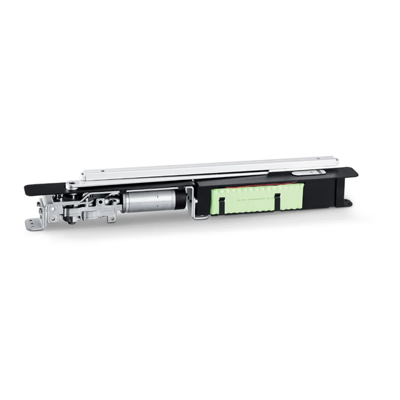
Product description 3. 1 System description and technical data The ECturn Inside is a swing door actuator operating fully automatically that is actuated by sensors or push buttons. The ECturn Inside operates electrically during opening and closing. ECturn Inside application... -
Page 7: Scope Of Delivery
ECturn Inside Scope of delivery Scope of delivery installation in the door leaf is shown, installation in the door frame is also possible 4. 1 Overview 0–20 m Cover for the motor gear unit Motor gear unit Back check (mat.no.129343) Power supply cable 2.5 m... -
Page 8: Dimensions
Dimensions ECturn Inside Dimensions 5. 1 Dimensions when installed in timber door leaf 5. 1 . 1 Main dimensions 12.5 Dimensions K (mm)* Spindle extension (mm) without Values between by slightly bending the lever 5. 1 .2 Installation situation Lever... - Page 9 ECturn Inside Dimensions 5. 1 .3 Prepared frame Dimensions or positions can deviate depending on the door type 5. 1 .4 Preparation of door leaf 591* (832) Dimensions or positions can deviate depending on the door type Rebate for programme switch...
-
Page 10: Dimensions When Installed In Wooden Frame
Dimensions ECturn Inside 5. 1 .5 Security sensors Make sure that fixing screws and drill holes do not cross the motor gear unit. Dimensions or positions can deviate depending on the door type Security sensor "Open" Security sensor "Close" Drill hole Ø 8 mm for connection cable for the "Close" sensor Drill hole Ø... - Page 11 ECturn Inside Dimensions 5.2.2 Installation situation Cable Ø 6.5 mm in the frame for low voltage Motor gear unit Control unit Guide rail Lever Door hinge 5.2.3 Prepared frame Dimensions or positions can deviate depending on the door type...
- Page 12 Dimensions ECturn Inside 5.2.4 Preparation of door leaf 564* Dimensions or positions can deviate depending on the door type Rebate for lever 5.2.5 Security sensors Make sure that fixing screws and drill holes do not cross the motor gear unit.
-
Page 13: Dimensions When Installed In Metal Door
ECturn Inside Dimensions Dimensions when installed in metal door 5.3. 1 Main dimensions 12.5* 66.5 302.5 608.5 Dimensions or positions can deviate depending on the door type Values between by slightly bending the lever Dimensions K (mm)** Spindle extension (mm) without 5.3.2... - Page 14 Dimensions ECturn Inside 5.3.3 Prepared frame Dimensions or positions can deviate depending on the door type 5.3.4 Preparation of door leaf 123.5 302.5 133.5*** 839** Rebate for programme switch...
-
Page 15: Dimensions When Installed In Metal Frame
ECturn Inside Dimensions 5.3.5 Security sensors Make sure that fixing screws and drill holes do not cross the motor gear unit. Security sensor "Open" Security sensor "Close" Drill hole Ø 8 mm for control unit connector cable. Drill hole Ø 8 mm for connection cable for the "Close" sensor Dimensions when installed in metal frame 5.4. - Page 16 Dimensions ECturn Inside 5.4.2 Installation situation Cable Ø 6.5 mm in the frame for low voltage Motor gear unit Control unit Guide rail Lever Door hinge 5.4.3 Prepared frame 123.5 302.5 133.5 5.4.4 Preparation of door leaf (839) Dimensions or positions can deviate depending on the door type...
-
Page 17: Installation
ECturn Inside Installation 5.4.5 Security sensors Make sure that fixing screws and drill holes do not cross the motor gear unit. Security sensor "Close" Security sensor "Open" Drill hole Ø 8 mm for control unit connector cable (5) Drill hole Ø 8 mm for connection cable for the "Open" sensor... - Page 18 Installation ECturn Inside Install the control unit. Connect the rotary encoder cable of the motor gear unit.
- Page 19 ECturn Inside Installation Connect the 24-V cable of the motor gear unit. If a radio board (optional) is used: Now install the radio board, see page 29.
- Page 20 Installation ECturn Inside Electrical connection Push the 6-wire cable (1) (2x 1 mm² for 24 V / 4x 0.25 mm² for electric strike, contact sensor etc.) into the pre- pared door passage from above and through the drip loop. In the case of metal doors, this cable is already inserted when the door is built.
- Page 21 ECturn Inside Installation Route the cable (4) further through the door leaf and the drip loop of the door leaf. Route the cable (4) through the drip loop (5) of the frame. Secure with strain relief (7). Use the cable (4) to form a loop near the interface (8).
- Page 22 Installation ECturn Inside Installing the guide rail...
- Page 23 ECturn Inside Installation Connect the lever to the motor gear unit. Hooks must face one another always use the 2-piece Nordlock lock washer – with O-ring fixed to M6x45 screw – (O-ring stays in place) 8 Nm +2...
-
Page 24: Installation Type Metal
Installation ECturn Inside 5 Nm +2 Installation type metal 6.2. 1 Preparatory work See chapter 6.1.1. 6.2.2 Installation on the door leaf Install the bracket on the motor gear unit. - Page 25 ECturn Inside Installation Install the motor gear unit in the door leaf. Route the cable strand from the motor gear unit to the control unit. The further steps are similar to the ones for wood, section 6.1. Connect the motor gear unit, see 18.
-
Page 26: Install Optional Features
Installation ECturn Inside Install optional features 6.3. 1 Rechargeable battery... - Page 27 ECturn Inside Installation 6.3.2 Separate programme switch...
- Page 28 Installation ECturn Inside...
- Page 29 ECturn Inside Installation 6.3.3 Radio board Hook in using your finger or a tool (notch) and carefully lift out the control circuit board hook in using your finger or a tool and carefully lift out the control circuit board...
-
Page 30: Commissioning
Adjustment of the space between the drive (door) and the guide rail (frame) is not easy after installation has been completed. When the ECturn Inside is installed in a wooden door leaf, the space can be reduced by shimming the motor gear unit if necessary. -
Page 31: Notes
ECturn Inside Notes Notes... - Page 32 E-Mail: leonberg.de@geze.com Baltic States Iberia Scandinavia – Norway GEZE GmbH Lithuania / Latvia / Estonia GEZE Iberia S.R.L. GEZE Scandinavia AB avd. Norge Niederlassung Süd-Ost E-Mail: info.es@geze.com E-Mail: baltic-states@geze.com E-Mail: norge.se@geze.com Tel. +49 (0) 7152 203 6440 www.geze.es www.geze.no Benelux E-Mail: muenchen.de@geze.com...
Need help?
Do you have a question about the ECturn Inside and is the answer not in the manual?
Questions and answers