Table of Contents
Advertisement
Quick Links
Advertisement
Table of Contents

Subscribe to Our Youtube Channel
Related Manuals for Davey microlene MCS


Summary of Contents for Davey microlene MCS
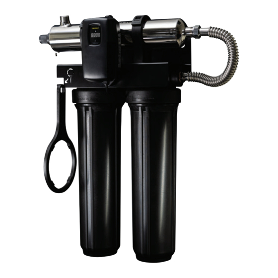
- Page 1 Aquashield Centurion 3 Stage UV Disinfection System Models: MCS & MCXS (without cartridges) KMCS & KMCXS (with cartridges included) Installation and Operating Instructions Flow Rate 57 L/min (30mJ/cm @ 95% UVT) AS/NZS: 3497 Please pass these instructions on to the operator of this equipment.
- Page 2 Aquashield Centurion 3 Stage UV Disinfection System Congratulations on purchasing this ultraviolet disinfection system. By purchasing a Davey Microlene UV Disinfection system you are receiving not only a high quality product but also peace of mind. Protecting your water supply with a UV system gives you reassurance that your family will have access to safe drinking water throughout your entire home protecting from microbiological contamination.
-
Page 3: Table Of Contents
Contents Safety Considerations....................4 Before You Begin ......................4 Water Quality Parameters ..................5 Assembly........................6 System Sizing ......................7 Location ........................7 Orientation ........................8 Installation ........................9 System Disinfection ....................12 Cleaning the Quartz Sleeve ..................12 Cleaning the UV Sensor ...................13 Operation ........................13 MCS Controllers ....................14 MCXS Controllers ....................14 MCXS Power-up Sequence ................14 MCXS Operational Screens................15 MCXS (with optional sensor) Operational Screens .........16... -
Page 4: Safety Considerations
Safety Considerations Although your UV system has been manufactured to the highest safety standards, care must be followed when operating and/or maintaining your system. Please read the instructions. - This appliance contains a UV-C emitter. - Unintended use of the appliance or damage to the housing may result in the escape of dangerous UV-C radiation. -
Page 5: Water Quality Parameters
Turbidity: < 1 NTU Tannins (organics): <0.1 ppm (0.1 mg/L) UVT (transmittance): 85% (Please contact Davey if water has a UVT that is less than 80% for pre-treatment recommendations) You can have your water tested via your local dealer or a private analytical laboratory. -
Page 6: Assembly
Assembly The Microlene Aquashield Centurion 3 Stage UV disinfection system is designed with a single inlet and outlet port. Unpack the system and ensure all the components are included in the box. Your system is shipped with the following components: 1 Controller MCS-CONT (fits all MCS series units) MCXS-CONT (fits all MCXS series units) -
Page 7: System Sizing
Location Choose a location where the main cold water line is accessible. The system must be installed after other water treatment equipment (i.e. softener), but before any branches (See Figure 1). Figure 1. Typical Installation To facilitate lamp removal, ensure there is enough space at the lamp connector end to safely remove the UV lamp and/or quartz sleeve (See Installation Figure 3). The controller will require a Residual Current Device (RCD) outlet and should be mounted beside or above the chamber. -
Page 8: Orientation
Orientation This system has the ambidextrous capability of being able to have the main water inlet enter from either the left hand side or right hand side of the unit. The unit comes pre plumbed from the factory for a left hand water inlet. To change to a right hand water inlet follow these simple steps (See Figure 2): Step 1: Remove the two black filter sump housings from the filter head and set aside. -
Page 9: Installation
Installation Step 1: Once both the orientation and location have been selected, securely fasten the rack to a suitable backing. As the rack system is extremely heavy when filled with water, it is imperative that the rack be mounted with suitable fasteners for the particular installation. Mounting to a plasterboard backing is not suitable, unless the rack is fastened directly to the wall studs. - Page 10 rack system. If the orientation was switched, the cartridge placement must also be switched. Once the cartridges are in place, use the supplied filter wrench to “snug” the filter housing onto the filter head (See Figure 5). Figure 5. Cartridge Removal Step 9: Install the UV sensor (optional and only compatible with the MCXS system, not compatible on the MCS standard controller). Align the flat portion so it faces the gland nut end and matches up with the half metal lip on the sensor port (see Figure 6).
- Page 11 Step 10: Install the lamp key into the controller (MCXS/KMCXS systems only). The key always comes packaged with the lamp and sits on the connector. With the key removed from the lamp, orient it so the label is upright and facing you. The key will plug into the lamp key port on the right side of the controller (Figure 8).
-
Page 12: System Disinfection
System Disinfection With a new installation, or any time the UV system is shut down for service, without power, or is inoperative for any other reason, the lines in the home or facility could be contaminated. Use the following steps to fully disinfect the lines throughout the entire home or facility. -
Page 13: Cleaning The Uv Sensor
Step 9: Using a soft, lint-free cloth or towel wipe the sleeve down using a commercial scale cleaner (i.e. CLR or similar). This removes scaling or iron ® deposits that may be on the outside of the quartz sleeve. Be careful not to get any moisture or liquids inside of the sleeve. Step 10: Dry the sleeve with separate cloth. Step 11: Replace the o-ring and slide the sleeve back into the chamber following steps 7 and 8 from the installation section of the manual. -
Page 14: Mcs Controllers
MCS Controllers Simplistic in operation, these systems feature a tri-colour LED that indicating system status and a 4-digit display to indicate lamp life remaining. Pressing the button will change the display to indicate total running time. When the UV lamp is on and within its operating age, the LED will be green. -
Page 15: Mcxs Operational Screens
4-20 mA Module Check Remote Alarm Module Check A final module screen is displayed showing which specific modules were initialised. The controller then displays the lamp optimisation screen for 60 seconds to allow the lamp to reach its optimum output. Finally, a final “start-up complete” screen is displayed. The system will now be ready to disinfect water flow. all detected modules lamp reaching max output successful start-up MCXS Operational Screens On systems without the UV monitor, the default screen shows the Microlene Home Screen. -
Page 16: Mcxs (With Optional Sensor) Operational Screens
On systems with the UV monitor, the system will display the same screens as on the Microlene MCXS controller except the UV Intensity replaces the home screen. The UV Intensity screen displays the level of UV light detected by the sensor. UV intensity can be affected by poor water quality, scaling on the quartz sleeve and/or sensor, lamp failure or lamp expiring. -
Page 17: Lamp Replacement (Mcs Systems)
MCS System At any point during this sequence, the audible chirp or alarm can be deferred for seven days by holding the controller button down for a period of five seconds. The number of deferrals used will be displayed as below. Once the deferral expires, the alarm will sound once again. The deferral can be repeated up to three times. PLEASE NOTE: At any point after lamp expiration, the water may be unsafe for consumption and should not be consumed without another form of disinfection. -
Page 18: System Troubleshooting
System Troubleshooting Hard Alarms: The following give a constant audible alarm. If present, the solenoid valve is closed, and the 4-20, remote alarm and WiFi modules transmit the alarm. System Display Problem Resolution Reset lamp protection circuit – unplug unit for 10 seconds. -
Page 19: Temperature Management Devices
Soft Alarms: The following remaining errors give a 15 second audible chirp only. System Display Problem Resolution Ensure all modules are connected properly to the system and to each other. Modules can be tested The module indicated is no individually by plugging in longer communicating with one at a time and cycling the system. -
Page 20: Expansion Modules
Expansion Modules Microlene MCXS controllers incorporate an “Infinite Expandability Port” (IEP) which allows for expansion to the UV sensor and all other modules. Each module (including the sensor) comes with both a male and female connection. Connect any device to the controller and all subsequent devices are then connected into the female end of last device added in a “daisy chain” configuration. -
Page 21: Microlene Aquashield Centurion Uv System Specifications
Expansion Modules Microlene EQUIPMENT SPECIFICATIONS RACK-MOUNT UV SYSTEMS MODEL MCSX 30.1 USgpm Flow Rate 114 lpm (@16mJ/cm 6.84 m 15.0 USgpm Flow Rate 56.8 lpm (@30mJ/cm 3.4 m 12.0 USgpm Flow Rate 45.4 lpm (@40mJ/cm 2.7 m 20 micron sediment Filter Housing - 1 20PP20J 1 micron sediment... -
Page 22: Limited Warranty Statement
NOTES... - Page 24 Please ensure that you have made a copy of any data saved on your products. To the fullest extent permitted by law or statute, Davey shall not be liable for any loss of profits or any consequential, indirect or special loss, damage or injury of any kind whatsoever arising directly or indirectly from Davey products. This limitation does not apply to any liability of Davey for failure to comply with a consumer guarantee applicable to your Davey product under local laws and does not affect any rights or remedies that may be available to you under local laws.
Need help?
Do you have a question about the microlene MCS and is the answer not in the manual?
Questions and answers