Advertisement
Quick Links
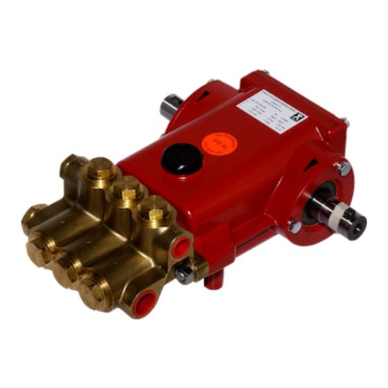
Montageanleitung Baureihe P30 / P31
Ventil- und Dichtmanschetten
Removal / Assembly - P30 / 31 Valve & Seal
Ventildemontage Druckseite
Stopfen herausdrehen. (Bild 1)
Federspannschale mit Spitzzange herausnehmen. (Bild 2)
Ventilfeder mit Spitzzange herausnehmen. (Bild 3)
Ventilplatte herausnehmen. (Bild 4)
Abzieher (Fa. Hoffmann 882600 Gr. 2) in den Ventilsitz
stecken, durch drehen aufspreizen. (Bild 5)
Ventilsitz mit dem Abzieher herausnehmen. (Bild 6)
O-Ring am Ventilsitz entfernen. (Bild 7)
Bild 2
Bild 4
Bild 6
Dismantling Valves on the Discharge Side
Screw out plugs (photo 1).
Bild 1
Remove spring tension cap with a taper-nose pliers (photo 2).
Remove spring with a taper-nose pliers (photo 3)
Remove the valve plate (photo 4).
Put the extractor tool (Messrs Hoffmann 882600 size 2)
on to the valve seat and turn to lock (photo 5).
Pull out the valve seat (photo 6).
Take the O-ring off the valve seat (photo 7).
Bild 3
Bild 5
Bild 7
D1772 1105S
Advertisement

Subscribe to Our Youtube Channel
Related Manuals for Speck P30


Summary of Contents for Speck P30
- Page 1 Montageanleitung Baureihe P30 / P31 Ventil- und Dichtmanschetten Removal / Assembly - P30 / 31 Valve & Seal Ventildemontage Druckseite Dismantling Valves on the Discharge Side Stopfen herausdrehen. (Bild 1) Screw out plugs (photo 1). Bild 1 Federspannschale mit Spitzzange herausnehmen. (Bild 2) Remove spring tension cap with a taper-nose pliers (photo 2).
- Page 2 Ventilmontage Druckseite Valve Assembly on the Discharge Side O-Ring in Ventilsitz einlegen (Bild 8) Place the O-ring in the groove of the valve seat (photo 8) Ventilsitz einlegen, rollierte glänzende Fläche (Dichtflä- Insert the valve seat so that the polished bright side che) nach oben.
- Page 3 Ventil- und Dichtmanschettendemontage Saugseite Valve and Seal Sleeve Disassembly on Suction Side Stopfen herausdrehen (Bild 16). Screw out the plugs (photo 16). Saugventilaufnahme herausnehmen (Bild 17). Take out the suction valve retainer (photo 17). Bild 16 Bild 17 Zerlegen der Saugventilaufnahme: Dismantling the Suction Valve Retainer Ausdrücken der Federspannschale (Bild 18).
- Page 4 Dichtmanschettendemontage: Disassembling the Seal Sleeves O-Ring herausnehmen (Bild 24) Take out the O-ring (photo 24). Distanzring entnehmen (Bild 25) Spacer ring (photo 25). Druckfeder entnehmen (Bild 26) Take out the pressure spring (photo 26). Bild 24 Bild 25 Bild 26 Dachmanschetten, Stützring und Druckring mit weichem Tap out the V-sleeves, support ring and pressure ring Stab (Kunststoff) d=21 herausdrücken (Bild 27)
- Page 5 Ventil- und Dichtmanschettenmontage Saugseite Mounting Valves & Seal Sleeves on the Suction Side Dichtmanschettenmontage: Assembling the Seal Sleeves Druckring einlegen Nut nach oben. (Bild 29) Insert pressure ring with the groove facing up (photo 29). Druckring mit weichem Stab (Kunststoff) herunterdrü- Press down the pressure ring with a plastic rod (photo cken.
- Page 6 O-Ring einlegen. (Bild 38) Insert the O-ring (photo 38). Bild 38 Saugventilaufnahme Montage: Assembling the Suction Valve Retainer O-Ring am Ventilsitz montieren. (Bild 39) Put the O-ring on the valve seat (photo 39). Ventilsitz einlegen, blanke rollierte Kegelfläche nach o- Put in the valve seat with its curved side facing up (photo ben.
- Page 7 Montageanleitungehäuse Fixing and Removing the Valve Casing Ventilgehäuse Demontage Taking off the valve casing Pumpe einspannen, Ventilgehäuse Verschraubung lö- Clamp the pump and screw off the valve casing fixing sen. (Bild 1) nuts (photo 1). Bild 1 Ventilgehäuse mit Kunststoffhammer gerade nach vorne Using a plastic hammer, knock off the valve casing entfernen.
- Page 8 Ventilgehäuse Montage Mounting the Valve Casing Nutring und Stützring in das Zwischengehäuse eindrü- Press the grooved ring and support ring into the interme- cken. (Bild 8) diate casing (photo 8). O-Ring in das Zwischengehäuse einlegen. O-Ring mit Si- Silicon grease the O-ring and push it into the intermedi- likonfett benetzen.
Need help?
Do you have a question about the P30 and is the answer not in the manual?
Questions and answers