Advertisement
Quick Links
BETRIEBSANLEITUNG
OPERATING INSTRUCTIONS
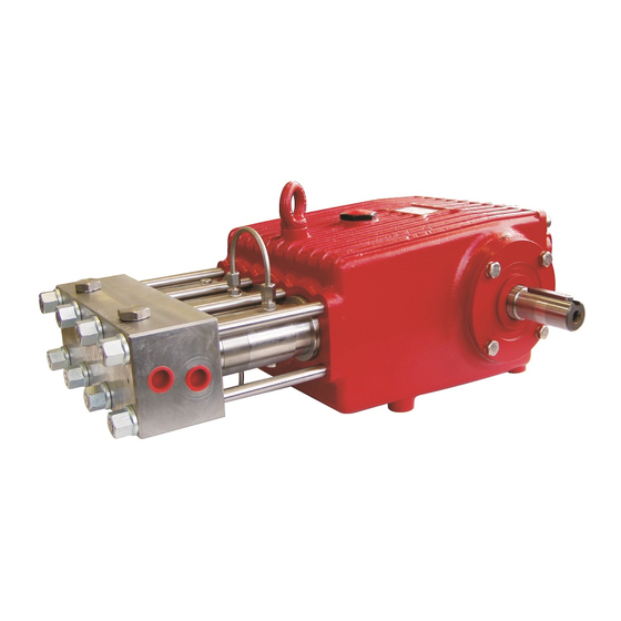
SPECK-TRIPLEX-PLUNGERPUMPE
SPECK TRIPLEX PLUNGER PUMP
Leistungsbereich - Performance
Type
Best.-Nr.
Code No.
P55/21-1000 00.6106
P55/26-800
00.6258
Ölfüllmenge: 4,6 Liter; Ölqualität ISO VG220 od. Kfz-
Getriebeöl SAE 90.
1. Allgemeines
1.1 Sicherheitsvorschriften:
Es ist ein Sicherheitsventil gemäß den "Richtlinien für
Flüssigkeitsstrahler" vorzusehen, das so eingestellt ist,
daß der Betriebsdruck um nicht mehr als 10% überschrit-
ten werden kann.
Bei Nichteinhaltung dieser Vorschrift sowie bei Über-
schreiten der Temperatur- und Drehzahlgrenze erlischt
jegliche Gewährleistung.
1.2 Einsatzbereich
• Die Pumpe ist geeignet zum Verpumpen von frischem,
sauberem (50µm gefiltertem) Wasser mit einer max.
Temp. von 40°C.
• Der maximale Betriebsdruck kann im Drehzahlbereich
von 600-850 1/min (600-1050 1/min bei P55/26-800)
genutzt werden. Bei weiterer Drehzahlreduzierung muß
im gleichen Verhältnis der Pumpendruck zurückge-
nommen werden, um eine ausreichende Getriebe-
schmierung sicherzustellen.
Leistungs-
Überdruck
Drehzahl
aufnahme
max.
Power
Pressure
Consump.
max.
kW
bar
41,6
1000
42,4
800
Förder-
Wasser
menge
temp.
max.
max.
max.
RPM
Output
Water-
Temp.
max.
max.
max.
-1
min
l/min
°C
850
20,9
40
1050
26,6
40
Oil: Use only 4,6 litres of ISO VG 220 or SAE 90 gear oil.
1.1 Safety Rules
Pump operation without a safety valve as well as any ex-
cess in temperature or speed limits automatically voids
the warranty.
The safety valve must be regulated in accordance with
the guidelines for liquid spraying units so that the admis-
sible operating pressure can not be exceeded by more
than 10%.
1.2 Fields of Use
• The pump is suitable for conveying fresh, clean water
(50 µm filtered) with a max. temperature of 40°C.
• Max. operation pressure is attainable at 600 - 850 rpm
(600-1050 1/min with P55/26-800). Should the rpm fall
below 600, the pump pressure must also be reduced
proportionally to ensure proper gear lubrication.
1
P55/21-1000
P55/26-800
Plunger
Hub
Gewicht
-Ø
ca.
Plunger
Stroke Weight
dia.
approx.
mm
mm
kg
16,0
46,0
82,5
16,0
46,0
82,5
1. In General
Vordruck
min/max
Inlet
pressure
min/max
bar
2,5/10
2,5/10
D1817 0113S
Advertisement

Related Manuals for Speck P55/21-1000


Summary of Contents for Speck P55/21-1000
- Page 1 BETRIEBSANLEITUNG OPERATING INSTRUCTIONS SPECK-TRIPLEX-PLUNGERPUMPE P55/21-1000 SPECK TRIPLEX PLUNGER PUMP P55/26-800 Leistungsbereich - Performance Type Best.-Nr. Leistungs- Überdruck Drehzahl Förder- Wasser Plunger Gewicht Vordruck aufnahme menge temp. -Ø max. max. max. max. min/max Code No. Power Pressure Output Water- Plunger Stroke Weight Inlet Consump.
- Page 2 2. Sicherheit 2. Safety Diese Betriebsanleitung enthält grundlegende Hinweise, die This Operation Manual gives basic instructions which are to bei Aufstellung, Betrieb und Wartung zu beachten sind. Da- be observed during installation, operation and maintenance her ist diese Betriebsanleitung unbedingt vor Montage und of the pump.
- Page 3 2.4 Sicherheitsbewußtes Arbeiten 2.4 Compliance with Regulations pertaining to Safety at Work Die in dieser Betriebsanleitung aufgeführten Sicherheits- When operating the pump, the safety instructions con- hinweise, die bestehenden nationalen Vorschriften zur tained in this manual, the relevant national accident pre- Unfallverhütung sowie eventuelle interne Arbeits-, Be- vention regulations and any other service and safety in- triebs- und Sicherheitsvorschriften des Betreibers sind zu...
- Page 4 2.6 Sicherheitshinweise für Wartungs-, Inspektions- 2.6 Safety Instructions for Maintenance, Inspection und Montagearbeiten and Assembly Work Der Betreiber hat dafür zu sorgen, daß alle Wartungs-, It shall be the plant operator’s responsibility to ensure Inspektions- und Montagearbeiten von autorisiertem und that all maintenance, inspection and assembly work is qualifiziertem Fachpersonal ausgeführt werden, das sich performed by authorized and qualified personnel who...
- Page 5 4. Aufstellung und Anschluß 4. Set-Up and Installation Die Pumpe ist waagerecht auf einem soliden The pump is to be mounted horizontally onto a Rahmen zu montieren auf dem auch der An- solid frame that is also to accommodate the triebsmotor zu montieren ist.
- Page 6 b) Druckleitung b) Discharge Line • Der Pumpe sind zwei spezielle konische Dichtkegel (64) • The pump comes with two special conical seals (64) beigelegt, die in die Druckanschlüsse der Pumpe einge- which have to be inserted in to the discharge ports of legt werden müssen.
- Page 7 Hydraulischer Aufbau: Hydraulic System Set-Up 4.2 Druckspeicher 4.2 Pressure Accumulator Der Druckspeicher, falls vorhanden, soll die Pulsation The purpose of the pressure accumulator, if installed, is HD-Pumpe dämpfen Vibrationen to damp pulsation from the high pressure pump and thus Druckleitung zu vermeiden. Die Gasvorspannung des avoid vibrations in the discharge line.
- Page 8 5. Inbetriebnahme 5. Operation Inbetriebnahme und Wartung Operation and Maintenance • Ölstand • Check pump oil level and if necessary fill up (as Pumpe kontrollieren ggf. entsprechend auffüllen (siehe Leistungsbereich, Seite 1). described on page 1 hereof). Erster Ölwechsel nach 50 Betriebsstunden; dann alle First oil change to be made after 50 hours of operation;...
- Page 9 6. Wartung und Instandhaltung 6. Maintenance and Repair Ventile überprüfen: To Check Valves: Druckventile: Discharge Valves: Sechskantmuttern (59) lösen, Ventilgehäuse (54) abzie- Remove hexagon nuts (59) and take off valve casing hen. Dichtungskassette (46) aus dem Ventilgehäuse (54) (54). Pull seal case (46) out of valve casing (54). Pull herausziehen.
- Page 10 Dichtungen und Plunger überprüfen: To Check Seals and Plungers Remove hexagon nuts (59) and take off valve casing Sechskantmuttern (59) lösen, Ventilgehäuse (54) abzie- (54). Remove the screw-in joints (37B) and take off the hen. Die Muttern der Ermetoeinschrauber (37B) lösen elbow pipes (37A).
- Page 11 Vor dem Zusammenbauen die Leckagebohrun- Check the leakage bores ø4 of the seal gen ø4 in der Dichtungshülse (36) und der Dichtungskasset- sleeves (36) and seal cases (46) for dirt and clean if te (46) auf Verschmutzungen überprüfen und ggf. reinigen. necessary.
- Page 12 Getriebe zerlegen: To Dismantle Gear Zuerst Ventilgehäuse und Dichtungshülsen demontieren, Disassemble valve casing and seal sleeves firstly; then dann Ölablaßstopfen (12) herausschrauben und Öl ab- screw out oil plug (12) and drain oil. lassen. Thereafter screw off gear cover (4) and bearing cover Anschließend Getriebedeckel (4) und Lagerdeckel (14) (14).
- Page 13 Zusammenbau: To Reassemble Auf einer Lagerseite des Getriebes Lageraußenring mit Using a soft tool, press in outer bearing ring on one side weichem Werkzeug einpressen bis dieser mit Außenkan- of the crankcase until its outer edge sits evenly on the te der Lagerbohrung bündig ist.
Need help?
Do you have a question about the P55/21-1000 and is the answer not in the manual?
Questions and answers